Note: Descriptions are shown in the official language in which they were submitted.
?~623~
PRESSURE REGULATED IMPLA~TABLE INFUSION PUM~
BACKGROU~D OF THE INVE~TION
The present invention relates to an implan-
table infusion pump. More particularly, the present
invention relates to an implantable infusion pump which
includes a pressure regulator apparatus for producing a
constant drive pressure from a more variable driving
force exerted on a drug solution contained in a variable
volume drug chamber of the implantable infusion pump.
Infusion pump designs rarely appeared in the
medical literature until the 1950s. Most of these early
infusion pumps were extracorporeal. One such device
included a reciprocating air pump driven by an electric
motor. Yet another design considered comprised a metal
housing for a glass syringe and a compression chamber
fed by a tank of nitrogen gas. Yet another such infu-
sion pump included a motorized syringe pump which
included an electric motor connected to the worm drive
that moved a syringe plunger by a gear box. The gears
were interchangeable such that replacement of the gears
permitted different delivery rates. Yet another infu-
sion pump included a syringe plunger driven by a rider
on a threaded shaft. ~umerous other designs were con-
sidered for these extracorporeal infusion pumps~ P.D.~'.
Soden in his thesis entitled, "A Methodical Design Study
of Miniature Profusion Devices For Chemotherapy of
Cancer of the Head and Neck", studied possible designs
for producing a miniature profusion device to be carried
by ambulating patients receiving chemotherapeutic treat-
ment for cancer of the head and neck. Quoting from histhesis, ~Approximately two million alternative design
solutions were synthesized and recorded in compact
matrix form on a 'morphological chart"'. One of the
numerous design concepts mentioned by Soden for possible
use with an extracorporeal infusion pump was the use of
--2--
a small tubular arrangement containing an elastic metal
~ellows possibly constructed from preloaded disks so as
to form a relatively small diaphragm in the tubular
arrangement for exerting a fairly constant force on the
drug solution being infused. Due to the size of the
diaphragm, this design provided for very little, if any,
compensation for changes in atmospheric pressure.
One of the earliest implantable infusion pumps
intended for use in laboratory animals comprised a
micro-injector comprising a compressed spring held a~ay
from a rubber-capped glass tube by a metal alloy disk
with a low melting point. Administration of the injec-
tion was accomplished by placing the animal near the
coils of a high-frequency induction heater. Ac~ivation
of the coils melted the alloy disk and the spring
ejected infusate into the desired site in the animal. A
second implantable infusion pump for the continuous
infusion of drugs utilized the osmotic pressure deve-
loped by a saturated aqueous solution of Congo red dye
against water as its power source. The infusion pump
comprised a partially collapsed rubber compartment
filled with Congo red dye separated from a second water
compartment by a semi-permeable cellophane member.
Expansion of the rubber compartment as the water moved
2~ by osmosis into the Congo red solution ejected the drug
fro~. the infusion pump.
Implantable infusion pumps were clinically
introduced in 1975. Implantable infusion pumps
currently in clinical use or in animal trials antici-
patin~ clinical studies in the near future, include~apor pressure powered pumps, peristaltic pumps, and
pulsatile solenoid pumps. The vapor pressure powered
pump was developed at the University of Minnesota and is
described hereafLer. The peristaltic pump generally
3~ comprises a flexible tube placed in 2 u-shaped chamber
"~
-
--3--
in contact with rollers that press against the tube with
sufficient force to occlude the tube's lumen. The
rollers are rotated by a motor. As the rotor turns and
the rollers compress the lumen of the tube, fluid is
moved toward an exit. The rollers and housing are
arxanged so that a second roller begins to squeeze the
tube before the first disengaged, preventing backflow of
the infusate. Sandia Laboratories, Siemens AG, and
Medtronic, Inc. have developed implantable pumps with
peristaltic pumping mechanjsm5~ A pulsatile solenoid
pump includes a solenoid driven reciprocating chamber
with two check valves to move infusate from the reservoir
out through the delivery catheter. Infusate is stored
in a flexible metal diaphragm reservoir. Such a pump
has been developed by Fischell and colleagues at Johns
~opkins University Applied Physics Laboratory and by the
Pacesetter Corporation.
Much- effort has been expended in developing
external infusion devices which provide a steady
pressure on the drug solution so as to provide a steady
flow of drug solution to the patient. For example, U.S.
Patent Nos. 2,815,152 and 3,023,750 as well as French
Patent 1,314,002 are examples of such devices.
Currently available lmplantable infusion pumps
also have difficulty in maintaining constant pressure as
the volume of the drug solution in their drug chambers
changes. Typically, the output flow of drug solution is
regulated by external means, an example of which is
il7ustrated in U.S. Patent No. 4,299,2~0, or if passive
flow restrictors are used to control the drug solution
output, flow variation must be tolerated. The two
ambient conditions that commonly cause flow variation
are temperature and atmospheric pressure. In the vapor-
pressure powered infusion pl~mp disclosed in U.S. ~atent
3~ No. 3,731,~81, both of these conditions cause the
. "
'1~
--4--
pressure differential between the drug chamber and the
internal Dody pressure to change thereby causing a
corresponding change in drug solution flow rate from the
infusion pump into an infusion site in the body. In
addition, the spring action of the metal bellows typi-
cally used to separate the drug solution from the two-
phase fluid adds a variable force to the otherwise
volume independent force exerted by the vapor pressure,
thereby causing a steady, although predictable decline
in flow rates as the drug chamber empties.
In many applications it is necessary to change
the flow rate of the drug solution freguently, more fre-
guently than can be done by changing the concentration
by an empty-refill cycle on a constant flow rate infu-
sion pump. Examples of such a~plications are: (1) thedelivery of insulin to a brittle diabetic with no resi-
dual insulin production, (2) the delivery of a che-
motherapeutic agent that has a strons dependence on
biological timing, or (3) the delivery of a hormone that
is timed to the natural rhythm of the body~
Infusion pumps; for example, U.S. Patent Nos.
4,373,527 and 4,146,02~, have been developed which uti-
lize electronic controls that respond to transmitted
electromagnetic signals and thus can be programmed by a
non-invasive procedure. The electronics in these infu-
sion pumps work relatively well due to the availability
of very complex, low powered integrated circuits.
90wever, such infusion pumps have complex flow control
components that must respond to the electronic signals.
An approach commonly used is to have the flow control
i device provide an impulse of drug solution flow for
every impulse of electrical signal from the electronic
¦ control circuit. By having very small (microliter)
individual impulses and repeating them within the normal
clearanc time of an infused drug solution in the ~lood
' '.
J
,~
--5--
stream (e.g. one to ten minutes), an approximation of
steady flow is obtained. This method is very flexible
in that both steady flow and variable flow up to bolus
doses can be delivered by a single flow control mecha-
nislD~ ~owever, the high cycle rate of the flow control
mecha~ism in~eases the wear rate of the components,
increases power losses in start and stop events, and
increases probability of failure of some component. If
a particular component has a finite failure rate per
cycle, the mean time to failure decreases as the rate of
cycling goes up. When a repeatedly cycled valve is used
to produce a constant flow rate for an extended time
period (several hours) there is an unnecessary hazard
involved that would not be present if the same fixed
flow rate ~ere achieved by other means. If the fixed
flow rate were known, a simple capillary tube could
deliver that rate with only one cycle of valve open and
fixed dose, rather than a hundred or so open dose cycles
which might be required in an electronic impulse
controlled sys~em.
Typical systems employed in such electroni-
cally controlled infusion pumps include: (a) cyclic
filling and emptying of a small drug accumulator with
~ upstream and downstream valves; (b) an active piston
i 25 pump with passive valves, and (c) miniature roller
(peristaltlc) pumps. In all three of these mechanisms,
the drug solution storage chamber is passive and is held
I at a fixed pressure usually a little above atmospheric
i pressure in order to suppress bubble formation from
1 30 dissolved air. The low pressure serves to reduce the
potential hz2ard of an infusator leak. ~ccumulator
systems use a higher drug chamber pressure to set posi-
tive filling cycles.
The above described electronically controlled
infusion pumps have an unnecessarily wide dynamic range
.~
..
and response time for many applications. Moreover, they
are complex, expensive and subject to failure. On the
other hand, the fixed flow rate infusion pump has been
shown to provide adequate therapy for a range of disease
states with no flow control for a given cycle. An infu-
sion pump is required which provides a degree of drug
solution flow control which is better than currently
available infusion pumps of the constant flow design but
which is less complex than that of the presently
available electronically controlled infusion pumps.
The present invention solves these and many
other problems associated with currently existing infu-
sion pumps.
SUMMARY OF THE INVENTION
The present invention relates to an apparatus
and method for controlling the pressure applied to a
drug solution in the drug chamber of an implantable
infusion pump.
The preferred embodiment of the present inven-
tion utilizes a pressurized support piston and-pressure
regulator arrangement to produce a constant force (drive
pressure) on a drug solution in the drug chamber from a
more variable driving force that might be a spring
mechanism or any other force producing device.
, Moreover, the pressure can be maintained without sub-
! jecting the drug solution to the high shear force at the
exit port of the pressure regulator.
, A preferred embodiment of the present inven-
j 30 tion readily lends itself to electronic control wh2re~y
~ the flow rate of the drug solution can be changed by
! transmitted electromagnetic signals. Moreover, the
electronic control can be preprogrammed to vary the àrug
'5~ solution flow rate as re~uiredO
3~
--7--
The present invention provides an electroni-
cally controlled infusion pump which is less complex
than existing, electronically controlled infusion pumps.
In an electronically controlled embodiment of the pre-
sent invention, telemetry can be used either to directlyset the re~erence pressure of the infusion pump's regu-
lator by supplying telemetered power to an otherwise
passive motor control circuit or provide commands to an
electronic timing circuit that can execute the command
at a later time using internal battery power. Many
applications of the infusion pu~p of the present inven-
tion will require only a non-invasi~e method of
resetting the drug Solution flow rate and maintaining
the flow rate until the next cycle time. An example of
this might include most insulin delivery systems where
the increase in flow rate to adjust for mealtime demand
is done by the patient on his/her own schedule (e.g. at
night the insulin flow rate is typically reduced to
adjust for the lower demand during sleep). In applica-
tions where drug solution is delivered on a fixedvariable rate schedule, such as in the case of hormone
or chemotherapeutic agents, the infusion pump of the
present invention can be preprogrammed and not reguire
any intervention by the patient.
~5 The preferred embodiment of the present inven-
tion has a variable volume drug chamber formed partially
by a movable, relatively rigid diaphragm which moves
under the influence of a force producing device to
expel the drug solution from the drug chamber.
,3~ ~ovement of the diaphragm is opposed by a column of
;pressllrized fluid, herein referred to as a support
piston, whose pressure is controlled by the reference
pressure of a pressure regulator apparatus so as to
allow only a constant force to be applied by the
diaphragm on the dru3 sclution in the drug cham~er. Any
3~
--8--
excess force exerted by the diaphragm is absorbed by t~e
support piston~ The re~erence pressure of the regulator
is interconnected to the support piston by a one-way
flow valve which regulates ~luid flow from the support
piston to a reference pressure chamber of the regulator.
In the preferred embc,diment, the regulator need only
release fluid from the support piston at a controlled
rate in order to maintain constant drug solution
pressure.
In some embodiments of the present invention,
the reference pressure of the regulator will be
preselected by appropriate configuration of a force
producing device such as a spring device which acts
on a diaphragm of the regulator so as to produce
the reg~lator reference pressure.
In various embodiments of the present inven-
tion, the pressure regulator can maintain either an
absolute internal drug chamber pressure or a relative
internal drug chamber pressure wherein the regulator
compensates for atmospheric pressure so as to maintain a
constant pressure differential between the drug chamber
and the internal body pressure.
In various embodiments of the present inven-
tion, the support piston will utilize a closed system
2~ wherein its operating fluid is kept separate from the
drug solution or an open system wherein the drug solu-
tion itself is used as the operating fluid of the sup-
! port piston.
1An advantage of the regulator of the present
j30 invention is that power is required only to change the
jreference pressure of the regulator in order to change
the drug solution flow rate. The actual work needed to
ideliver the drug solution at the selected flow rate is
<accomplished by the pressure of the drug chamber. The
35 pressure of the drug chamber can be readily varied by
- 9 -
changing the reference pressure of the regulator since
the dr~g chamber pressure is the difference between the
total force being exerted by the drug chamber diaphraqm
and the countering force of the support piston whose
pressure is controlled by the re~erence pressure of the
regulator. In the preferred embodiment, to reduce drug
chamber pressure, the regulator decreases the outflow of
fluid from the support piston. In order to increase the
drug cha~ber pressure, the fluid in the support piston
is released more rapidly by the regulator. Accordingly,
the regulator need only vary the flow of fluid out of
the support piston in order to vary drug chamber
pressure.
An advantage of the present invention is that
by using a variable drug chamber pressure design, much
of the safety and ease of use of the steady flow infu-
sion pump designs is retained.
An eléctronically controlled embodiment of the
present invention might use an electromechanical
arrangement to compress or expand the regulator
diaphragm in order to vary the reference pressure of the
regulator.
These and various other advantages and
features of novelty which characterize the present
2~ invention are pointed out with particularity in the
claims and next hereto and forming a part hereof.
However, for a better understanding of the invention,
its advantages and objects obtained by its use,
reference shou~d be had to the drawings which form a
further part hereof and to the acco~,panying descriptive
matter in which there is illustrated and described a
preferred embodiment of the present invention.
,~
3~
,,
--10--
BRIEF DESCRIPTIO~ OF THE DRAWINGS
_
In the drawings, in which like reference
numerals and letters indicate corresponding part
throughout the several views;
5Figure 1 is a diagrammatic/cross-sectional
view of an embodiment of the present invention wherein
the regulator compensates for atmospheric pressure;
Figure 2 is a diagrammatic/cross-sectional
view of an embodiment of the present invention wherein
the drug solution is used as the support fluid of the
support piston;
Figure 3 is a diagrammatic/cross-sectional
view wherein the regulator does not compensate for
atmospheric pressure;
1~Figure 4 is a diagrammatic/cross-sectional
view of an embodiment of the present invention wherein
the regulator does not compensate for atmospheric
pressure and the drus solution serves as the support
fluid for the support piston;
20Figure 5 is a diagrammatic/cross-sectional
view illustrating an electronically controlled embodi-
ment of the present invention;
Figure 6 is a diagrammatic/cross-sectional
view illustrating a possible packaging arrangement of
2~ components of an embodiment of an infusion pump in
accordance with the princip.les ~f the present invention;
Figure 7 is a diagrammatic/cross-sectional
view of an e~bodiment of the present invention which
utilizes an adjustable force applicator device for
varying the reference pressure of the regulator,
Figure 8 is an enlarged partial sectional view
of the regulator valve in an increased flow setting, and
Figure 9 is a view similar to Figure 8 wherein
the regulator valve is in a reduced flow setting.
~ `:
. .
DETAILED DESCRIPTI~N OF A
PREFERRED EMBODIME~T OF THE PRESE~T INVE~TIO~
Referring now to the drawings, there is
illustrated in Figures 1 through 7 various embodiments
of an implantable infusion pump in accordance with the
principles of the present invention, the infusion pump
being generally referenced by the reference numeral 20.
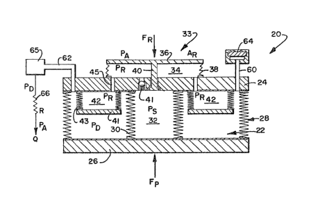
The embodiment of the infusion pump 20 illustrated in
Figure 1 includes a variable volume drug chamber 22
formed by a wall structure 24 of the infusion pump 20
and a diaphragm 26 interconnected to the wall structure
24 by a spring arrangement 28. The spring arrangement
28 functions as a force producing (Fp) device causing
the diaphragm 26 to exert a variable force on the drug
solution in the drug chamber 22. It will be appre-
ciated, that any other number of force producing devices
might be used to exert a force on the drug solution.
Interconnecting the wall structure 24 to the diaphragm
26 is a cylindrical column of under pressure fluid
(Ps) enclosed by a flexible bellows arrangement 30
so as to form a support piston 32 which counters
the force being exerted by the diaphragm 26 on the
drug solution in the drug chamber 22. The support
piston 32 is interconnected to a regulator appara-
2~ tus 33 including a chamber 34 defined by adiaphragm 36 and force producing spring arrangement
38 which produces a predetermined force (FR) on the
diaphragm 36. The support fluid of the support
piston is interconnected to the regulator chamber
34 by a one-way valve arrangement 40 which controls
the fluid flow into the regulator chamber 34. It
will be appreciated that the spring 38 can exert a
variable force over a ranae of movemen' and still be
used to provide a predetermined force, since in opera-
tion, the diaphragm 36 will move very little. The valve
-
-12-
arrangement 40 will provide a steady, regulated flow.
In the embodiment shown in Figure 1, the support fluid
of the support piston 32 is contained in the regulator
chamber 34 and a chamber 42 interconnected to the
chamber 34 by a pathway 45 and including a diaphragm 41
and bellows 43 arrangement, so as to be kept separate
from the drug solution in the drug chamber 22.
Additionally, the diaphragm 36 is exposed to the inter-
nal body pressure which reflects the atmospheric
pressure. In this manner, the regulator 33 comprising
diaphragm 36 and spring bellows 38 is referenced to
atmospheric pressure and produces a constant flow rate
regardless of atmospheric changes.
The embodiment illustrated in Figure 2 utili-
zes the drug solution as the support fluid for the
piston 32 and thus does not include the fluid chamber
42. Since the drug solution itself is used as the sup-
port ~luid in`the support piston, it must pass through
the regulator v21ve 40. This embodiment achieves a
larger volumetric efficiency and a lower cost due to
fewer parts compared to electronic or vapor pressure
driven pumps. Moreover, the regulator diaphragm 36 is
exposed to the external pressure as illustrated in
Figure 1.
Figure 3 illustrates an embodiment of the pre-
sent invention wherein the regulator diaphragm 36 is
internally referenced to a chamber 50 enclosed by an
immovable shell structure 52, the chamber 50 being
filled with gas at atmospheric pressure (or lowe-).
This embodiment dGes not provide any reference to the
atmospheric pressure and as a result, has to operate at
a higher pressure ln order to avoid variation in
a.mospheric pressure. This embodiment, as well ~s that
shown in Figure 4 which has the same closed chamber 50
but no support piston fluid reservoir 42, are designs
~ ,.....
3~,~
s
-13-
that allow more freedom in construction since the small
regulator mechanism can be placed in the pump interior
with no connection to the exterior. It also provides a
sealed place for electronic controls that can mechani-
cally change the regulator pressure (PR) or set point.
In the embodiments illustrated in Figure 1 and~igure 3, at the end of a cycle when the drug chamber 22
is empty, most of the operating fluid of the piston 32
will be transferred to the chamber 42. When drug solu-
tion is injected into the infusion pump through therefill septum, the pressure (PD) in the drug
chamber 22 will rise and the diaphragm 26 will
retract producing negative pressure across the
regulator 33. This excess negative drug pressure
will cause the regulator 33 to close to allow the
internal pressure to fall to the control point. In
order to reset the infusion pump for another cycle,
a bypass check valve 41 responds to the negative
pressure and allows operating fluid to flow back
into the Support piston 32. When the infusion pump
drug chamber is full, the regulator 33 takes over
control of the drug chamber pressure as soon as a
small amount of drug solution has left the drug
chamber.
In the embodiment illustrated in Figures 2 and
4, the drug solution itself refills the support piston
chamber, through the check valve. The embodiment
illustrated in Figure 5 illustrates an electronically
controlled version of an infusion pump in accordance
with the principles of the present invention. In the
air space in the chamb0r 50 behind the regulator
diaphragm 36 there are placed conventional telemeter
receiver controlling circuits ~4 for receiving commands
from a telemetry transmitter 56 and for controlling
small electromechanical components or servomechanisms 55
~ `3
that can vary the force exerted on the diaphragm 36 and
thus vary ~he regulator reference pressure. It wiil be
appreciated that any number of well known devices might
be utilized. For example, this might be in the form of
a small electric motor and gear train that would
compress or expand the spring arrangement 38 supplying
the force on the diaphragm 36. Battery power would be
required only when the settings were changed. The tele-
metry transmitter and receiver could be of the type pre-
sently used for transcutaneous signal transmission andare availa~le commercially. Examples of such control
circuitry are disclosed in U.S. Patent ~os. ~,373,~27
and 4,146,029. Signal coding could be used to decrease
the possibility of accidental operation. The receiver
controls might be passive circuits that obtain their
power from the transmitter since they would be activated
only to change the pressure.
The regulator of the present invention is par-
ticularly suited to changing the reference pressure set
point slowly due to the slow flow rate out of the infu-
sion pump, and rapid changes in drug solution flow rate
are not particularly suited for this design. The
pressure control circuit would preferably be in the form
of an adjustable basal rate rather than the flexible
control used in other pumps that can be used to deliver
fast bolus flows. This slow control greatly increases
the safety of its operation.
The most con~pact design of an infusion pump of
the present invention uses the outer shell structure of
the infusion pump as a spring element that stores energy
in the form of tension and compression of the metal or
plastic material comprising the shell structure. The
reference pressure for the regulator can be o~tained
from either the top or bottom of the pump in the form of
3~ a thin, large diameter diaphragm that separates the
-15-
pressure transmitting fluid from ~he body tissue.
Figure 6 illustrates a possible packaging of the com-
- ponents of the embodiment illustrated in Figure 3.
As with other infusion pumps, such as U.S.
~ 5 Patent ~o. 3,731,681,
the present invention will include an inlet port 60 and
an outlet port 62. Suitably positioned in the inlet
port 60 is a self-sealing, penetrable septum member 64,
a filter 65 being posi~ioned in the outlet port. A
capillary flow restrictor 66 is interconnected to the
outlet port by a suitable connecter 68. The capillary
flow restrictor might then be interconnected to a
catheter for delivery of the drugs to an infusion site
in the body although any number of other well known
devices might be used. A convoluted diaphragm 67 is
utilized to allow nesting of the drug chamber diaphragm
26 therewith. (In this illustration, the regulator 34
is generally iilustrated without any of its individual
, components.)
i 20 The total force on the diaphragm 26 is opposed
by the sum of the drug solution pressure in the drug
cham~er 22 and the support piston 32 fluid pressure:
Fp ~ (PAAp) = (PsAs) + (PDAD)
wherein;
Fp =spring force of diaphragm
PA =pressure of atmosphere
Ap =area of diaphragm 26
Ps =pressure of fluid in support piston
~5 =2rea of support piston diaphragm
PD =pressure in drug chamber
AD =2rea of drug chamber di2phragm
Regulation of the drug solution pressure (P3)
occurs due to mechanical negative feedback action of the
valve 40 so 25 to maintain a balanced force on the
diaphragm 36. If the pressure (PD) of the drug solu~ion
dro~s s^ does the reaulator ~ressure (PR~ which causes
-16-
the valve 40 to open to allow entry of more of the fluid
from the support piston chamber which is at a high
pressure (Ps)~ This is illustrated in Figure 8 wherein
the valve 40 provides a larger opening 39 so as to allo~
more of the support solution in the support piston 32 to
flow into the regulator reservoir 34. Figure g
illustrates the valve 40 in a reduced flow setting
wherein a smaller opening 37 is provide for drug solu~
tion flow~ As illustrated in Figures 8 and 9, the valve
40 will preferably include a seal 35, such as an O-ring
or the like. This restores the balance forces on the
regulation diaphragm 36 by increasing regulator pressure
(PR). The control equations are:
PRAR ~ PAAR = FR
15 wherein;
PR =pressure in regulation chamber
AR -area of r~gulator diaphragm
PA =pressure of atmosphere
FR =spring force on regulator diaphragm
The fluid storage chamber 42 has a soft
bellows so the pressure (PD) is about equal to (PR).
Therefore, the drus chamber pressure can be expressed
as:
DAR ~ PAAR = FR
Solving for PD:
PD ~ FR + PA
AR
The flow through the capillary tube 66 is
expressed in terms of the pressure difference across it
divided by the fluid resistance:
Q = PD ~ PA
_
wherein,
^ Q =Clow in volume per unit time
R =fluid resistance of capillary
3~23
-17-
Solving for Q putting in terms for the
pressure PD:
RQ = PD - PA = FR + PA ~ PA
AR
The two terms for atmospheric pressure cancel
to give:
Q = FR
ARR
The regulator force `(FR), the regulator
diaphragm area (~) and the capillary resistance R are
fixed quantities, therefore, the flow Q will be fixed
independent of the atmospheric pressure and the force on
the drug chamber diaphragm 26. In a non-electronically
controlled version of the infusion pump, the regulator
force (FR) might be preset by selecting a spring member
38 which creates the required force (FR). In Figure 7,
another embodiment is illustrated wherein an adjustable
force applicator 25 is utilized to apply a predetermined
force (FR) on the diaphragm 36.
It is to be understood that even though the
above numerous characteristics and advantages of the
invention have been set forth in the foregoing descrip-
tion, together with details of the structure and
function of the invention, the disclosure is illustra-
tive only, and changes may be in detail, especially in
matter of shape, size and arrangement of parts with the
principles of the invention to the full extent indicated
by the broad general meaning of the terms in which the
appended claims are expressed.