Note: Descriptions are shown in the official language in which they were submitted.
~L~6~
CASTE~ PINTLE
.
sackground of the Invention
The presen-t lnvention relates to a novel pintle construction,
and more particularly to a novel pintle especially suitable
for supporting caster wheels.
One type of caster heretofore in general use for furniture,
carts and similar applications has included a wheel and axle
assembly, a forged metal pintle or stem pivotally or swivelly
connected to the wheel assembly and insertable into a socket
fixed to the furniture or other structure with which the
caster is to be assembled. Such heretofore suggested casters
have also included a resiliently deformable ring loosely
fitting in a groove in the pintle or stem and adapted
frictionally to engage the interior wall of the socket for
retaining the caster in assembled relationship with the
socket.
While such caster structures have been widely used, certain
problems have been encountered ~rom time to time. For
example, the metal, usually steel, from which the pintle is
forged, must be sufficiently soft to permit the forging
operation. As a result, such pintles may be subject to
damage or bending resulting from shocks or momentary
overloads to which the furniture or other article may be
subjected during use. Furthermore, with such heretofore
suggested structures, the resiliently deformable friction
ring may slip out of proper alignment prior to assembly with
the socket so that such assembly is made difficult or
impossible.
Summary of the Invention
Accordingly the present invention seeks to provide a novel
caster pintle capable of overcoming the aforementioned
difficulties.
,. . .:
- 2 ~ t~
More specifically, the present invention seeks to provi~e a
novel caster pintle which is su~Eicientl~ strong and
resilient to avoid damage from shoc~cs or rnomentary overloads
and which at the same time may ~e easily and econornically
configured for cooperative interenyagernent wi-th a caster
wheel assembly and a complementary socket.
Further, the present invention seeks to provide a novel
caster pintle o the above~described type which includes
means for maintaining a deformable friction ring properly
centered with respect to the pintle while permitting the
friction ring to be collapsed or deformed for facilitating
assembly in a complementary socket.
The invention in one broad aspect comprehends a caster pintle
comprising an elongated high tensile strength resilient metal
core, and a molded tough resilient organic plastic body
molded around and substantially encapsulating the core, the
body having a first end portion with means formed thereon for
ppivotally engaging a caster wheel means and a second
opposite end portion with means for engaging a complementary
mounting opening.
A still further aspect of the invention comprehends the
caster pintle comprising an elongated high tensile strength
hardened metal core, and a tough resilient plastic molded
body formed around and substantially encapsulating the core,
2S the body having at least one end with a groove for receiving
a friction ring, the groove having means integrally molded
therein for maintaining the ring in a position generally
concentric with a longitudinal axis of the body.
Another aspect of the invention pertains to a caster pintle
comprising an elongated high tensile strength resilient steel
core, and a molded tough resilient organic plastics body
molded around the core, the body having a first end portion
~or pivotal interengagement with caster w~leel meana and a
second opposite end portio~ for lnsertion into a
complementary moun-~ing opening. The second end portion has a
predetermined outside diameter and an annular rece5s having a
diameter less than the outside ~iarneter and a resiliently
deformable friction ring is disposed in the recess for
frictionally engaging an inner wall of the mounting opening
and resisting axial removal of the pintle from the mounting
opening. The friction ring has a normal outside diameter
greater than the diameter of the recess. Means are
integrally molded in the recess for initially centering the
friction ring with respect to the pintle body while
permitting the friction ring to be collapsed upon insertion
into the mounting opening.
Brief Description of the Drawin~s
Other aspects and advantages of the present invention will
become apparent from the following description and the
accompanying drawings wherein:
FIG. 1 is a perspective view showing a pintle incorporating
features of the present invention connected with a caster
wheel assembly;
FIG. 2 is an enlarged side elevational view showing a caster
pintle incorporating features of the present invention;
FIG. 3 is a fragmentary partial sectional view showing the
pintle of FIG. 2 associated with a caster wheel assembly and
also inserted into a complementary socket mounted in a piece
of furniture or other structure;
FIG. 4 is an enlarged fragmentary side elevational view of
the pintle o~ FIG. 2 showing a portion of the structure in
greater detail;
FIG. 5 is a sectional view taken along line 5-5 in FIG. 4
with the split friction ring omitted;
.
............... ~ ..... ...... . . .~...... .. .. ~ ...... I
~ 3
-- 4
FIGo 6 is an enlarged partial sectional view taken
along line 6-6 in FIG. 3;
FIG. 7 is a side elevational view showing a modified
form of the pintle of the present invention;
FIG. 8 is a somewhat schematic view showing means for
molding the plastic bodies along core wires of pintles
of the type shown in FIG. 7;
FIG. 9 is a fragmentary perspective view showing a
series of pintles molded with the means shown in FI~.
8; and
FIG~ 10 is a perspective view par~ially broken away
showing a further modified form of the present
invention.
~ iled_a~cri~ti~n Qf ~,~req~,~ed EmbQdim~nt
Referring now more specifically to the drawing~
wherein like parts are designated by the same numerals
throughout the drawings, a caster 10 i8 shown in FIG.
1 which includes a pintle 12 incorporating features of
the present invention connected with a wheel and axle
assembly 14 of known construction. As indicated, the
wheel and axle assembly may be of any known
constructuion and therefore need not be described in
detail~ It suffices to state that the unit shown
herein comprises a body member 16 carrying an axle 1~
which supports wheels 20 and 22. The body 16 includes
a socket portion 24 for receiving one end of the
pintle as will be described more in detail below.
- 5 ~
It will also be understood ~hat casters incorporating
pintles of the present invention may be assembled with
a wide variety of furniture pieces, carts or other
stru~ures. Such structures usually include a frame
member designated 26 for purposes of illustration in
FIG. 3 having an aperture 28 in which a socket 30 is
secured for receiving an upper end of the pintleO It
should be noted that the pintle 12 may be inserted
dixectly into a properly sized hole drilled directly
in the structure itself.
As shown best in FIGS. 2 and 3, a pintle 12 incorpor-
ating the present invention comprises a core element
32 formed from a high tensile strength resilient or
spring metal such as steel as distinguished from a
1;5 relatively soft malleable material such as low carbon
cold heading quality steel. This core gives the pintle
relatively great strength and resilience and the ability
to withstand impact loads and the like which would be
likely to result in bending or other permanent damage
to heretofore suggested caster pintles. It will be
noted that the core 32 is of extremely simple cylindri-
cal configuration and may be easily and economically
produced simply by cutting a length from a piece of
wire stock material.
The pintle 12 also includes a body 34 of tough resilient
organic plastic material molded around and, in this
embodiment, completely encapsulating the core 32. The
body 34 is formed with an exterior configuration com-
plementary to the socket portion 24 of the wheel assem-
bly and the socket 30, which configuration can be
easily and economically produced by a molding operation
rather than a forging or cold-framing operation pre-
viously re~uired for metal pintles.
- 6 ~
As shown in FIGS. 2 and 3, the plastic body 34 is
provided with a first or lower end portion 36 haviTIg
a diameter similar to the internal diameter of the
wheel and axle assembly sockek 24. This end portion
35 terminates in a tapered bevelled section 38 for
facilitating insertion into the socket 24. A groove
40 is formed in the end portion 36 adjacent to the
tapered section 38 for providing a radial shoulder 42
interengageable with complementary rib 44 formed on
the interior of the socket 24 for retaining the parts
in assembled relationship. It will be noted that the
plastic material of the body 34 is sufficiently
resiliently deformable to permit the shoulder 42 to be
snapped beneath the rib 44 during insertion of the
pintle into the socket 24. While the pintle fits
within the ocket 24 relatively closely, there is
sufficient clearance to permit the wheel assembly to
pivot or swivel freely relative to the pintle. Further-
more, the plastic material of the body 34 provides an
anti-friction bearing surface and may even have a
lubricant en~edded therein for promoting free swivel
movement between the wheel caster and the pintle.
Bottom of socket 24 has dome shaped bearing pad 45 to
support the pintle and allow free swivel of the socket
24 about the pintle 12.
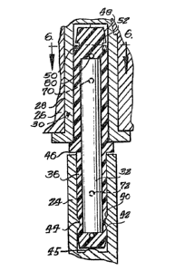
The plastic body 34 is formed with an upper or second
end portion 44 complementary to and adapted to be
inserted in the socket 30. An annular shoulder 46 is
provided on the plastic body 34 between the end
portions 36 and 44. This shoulder 46 is adapted to
engage the underside of the socket 30 so as to provide
a thrust bearing therebetween.
.~.
- 7 ~
Thrust is carried through the pintle 12 to the raised
bearing pad 45 in socket 24. The upper end portion
44 of the pintle has a diameter closely similar to the
internal diameter of the socket 30 so as to fit snugly
therein. A tapered section 48 is fo~.ed at the upper
terminal of the end portion 44 for facilitating entry
into the socket during assembly.
In order to enhance frictional interengagement between
the pintle and the socket 30, a resiliently deformable
friction ring 50 is assembled in a groove 5Z formed in
the end portion 44 immediately adjac~nt the tapered
section 48. The ring 50 is formed from a suitable
spring material such as spring steel and preferably is
split as indicated at 54 in FIGS. 2 and 6 so as to
lS facilitate collapsing. The ring 50 initially has a
diameter greater than the diameter of the end portion
44 and greater than the internal diameter of the
socket 30 so that it will have an interference friction
fit with the socket 30 when the parts are finally
assembled. It will be noted that the maximum diameter
of the tapered section 48 of the end portion ~g less
than the diameter of the remainder of the end portion
44 so that the split ring may be relatively easily
pushed over the end section 48 and snapped into the
yroove 52.
The groove 52 has a bottom or cylindrical surface 56
having a diameter substantially less than the internal
diameter of the ring 50 when the ring is in its normal
or undeformed condition. The smaller diameter of the
surface 56 is such as to permit the ring to be
. . .
- 8 -
collapsed for insertion into the bore of the socket
30~ In accordance with a further feature of the
present invention, means is provided in the groove 52
for maintaining the ring 50 substantially centered
with respect to the longitudlnal axis of the pintle
while still permitting the ring to be collapsed duriny
assembly with the socket 30~ This centering means
prevents the ring from sliding to one side in the
groove to such an extent that it would interfere with
the entry of the pintle into the ~ocket 30 thus making
assembly difficult or impossible. In the embodiment
shown~ this centering means comprises a first pair of
diametrically opposite thin ribs 58 and 60 extending
radially from the wall 56 and second and third pairs
of oppositely extending ribs 62, 64 and 66, 68
respectively projecting on extensions of chord~ of a
circle defined by the bottom 56O These ribs are
generally equally spaced around the bottom aurface 56
and have their outer ends disposed on an imaginary
20 circle having a diameter similar to the internal
diameter of the ring 50. Thus, the ribs serve to
center the ring with respect to the pintle.
The ribs 58 through 68 are relatively thin and are
resiliently deformable. Thus when the pintle is
inserted into the socket 30, the split ring 50 is
deformed or squeezed inwardly, which action is
permitted by the resilient deflection or deformation
of the ribs 58 through 68 as ~hown best in ~IG. 6. It
30 will be noted that the diametrically oppositely
extending rib~ 58 and 60 will be substantially crushed
by the ring while ~he ribs 62 through 68 will be
folded over as well as crushed so that the ribs
- 9
provide a resilient spring action enhancing the
inherent spring action o~ the riny 50 for rausing the
ring aggressively to engage the interior surface of
the socket 30.
As previously indicated, the body 34 i8 molded so as
to completely encapsulate the core 32. This is
accomplished by supporting core 32 centerly in a mold
cavity, not shown, by means of a plurality of locating
pins also not shown so that when the plastic material
is injected into the mold cavity, it will flow
completely around the core. When the mold is opened
and the locating pins are removed, the plastic body 34
is left with a plurality of holes. As indicated in
FIGS. ~ and 3, holes 70 and 72 are formed by locating
pins at one side of the mold and toward opposite ends
of he cavityO Complementary pairs of pins at
opposite side of the mold fsrm apertures or holes 74,
76 and 78, 80. The three point arrangement of these
holes and thus ~he locating pins is such that the core
is securely held in the mold cavity. An additional
locating pin i~ proYided adjacent one end of the
cavity for engaging one end of the core element and
thus locating it in the cavity and this pin provides
hole 80 shown in FIGS. 2 and 3.
In FIGS. 7, 8 and 9, there i8 shown a modified form of
the present invention which is ~imilar to the
structure described above as indicated by the
application of identical reference numerals with the
suffix ~ added to corresponding elements. In this
embodiment, the core element 32a extends entirely
through the plastic body 34a and thus is encapsulated
" - 1 0
except for exposed opposite ends 82 and 84. The
pintle of this embodiment is adapted to be formed in
the manner shown in FIGS. 8 and 9. More ~pecifically,
complementary mold halves 86, only one of which is
shown, are provided. These molds are formed with a
plurali~i- of cavities 88 and longitudinally extending
bores 90 adapted to receive a length of continuous
wire or core ~tock material 92 extending through a row
of aligned cavities. When the molding operation is
completed, a series of pintles 12a on the continuous
wire 92 is provided as shown in FIG. 9. This
arrangement facilitates locating the core material in
the mold cavities and further handling of the pintles.
As a further step in the manufacturing operation, the
15 sections of the wire g2 between the plastic bodies 34a
are severed by means not shown to produce the pintle
and the form shown in ~IG. 7.
.
FIG. 10 shows a further modified form of the present
2Q invention in which elements corresponding to those
described above are designated by the same reference
numerals with the suffix ~ added. In this embodiment~
the socket 30b adapted to be ~itted into a
complementary aperture in a piece of furniture or the
25 like is molded in~egral with the end portion 44b of
the body member 34b. This embodiment may be provided
with a core member 32b which extends entirely through
the plastic body as shown or which is entirely
encapsulated in the manner of the embodiment of FIGS.
30 1-~
While preferred embodiments of the present invention
have been shown and described herein, it is obvious
that many struc~cural detailG may be changed without
departing f rom the spirit ~nd scope of the appended
cl aims .