Note: Descriptions are shown in the official language in which they were submitted.
The Inventlon relates to a method for t.he admlnlstra-
tlon of Insulln or other long-term medlcamer1ts to the body of a
person.
A method of thls klnd Is, for instance, dlsclosed In
Austrlan PS 367 292. Devlces of slmllar functlon are for
example, also d I sc I osed In US-PS 3,840,009, US-PS 3,786,813, US-
PS 3,788,322 and 3,797,492.
All known systems have the dlsadvantage that the pres-
sure of the gas-fllled chamber of the reservolr Is dependent on
the body temperature of the long-term patlent. The dlsadvantage
Is therefore that only predetermlned quantltles of medlcament can
be admlnlstered, extra dosages as requlred are not posslble.
The present Inventlon provldes for further development
of the conventlonal devlces, as above, In such a way that extra
dosages as requlred Is made posslble.
Accordlng to ~he present Inventlon therefore there Is
provlded a method for the admlnlstratlon of a long-term medlca-
ment to the body of a person, comprlslng: provldlng a dosage
devlce havlng two chambers separated by an elastlc membrane, pro-
vldlng a quantlty of the medtcament In one of sald chambers and
providlng a quantlty of llquld propellant In the other chamber,
sald propellant havlng a temperature-dependent vapour pressure to
malntaln pressure on the medlcament substantlally contlnuously to
!nJect med~cament ~nto the body vla an outlet from the medlcament
chamber, determlnlng the need of the body for the medlcament by
senslng a blood component at certaln tlmes, and varylng the tem-
peratUre of the propellant to vary Its vapoUr pressure In accor-
dance wlth sald determlnatlon of need ~or the medlcament at sald
certain tlmes to control the quantlty of medlcament InJected into
the body at sald certaln tlmes.
Thus, In the method of the Inventlon the temperature of
. .
the propellant gas, and thereby the pressure and thus the
Increased dosage a~ the requlred tIme Interva 15, Is Increased
externally. It Is preferr-ed that Inductlve of capacltlve
coupllng Is used as a means of temperature Increase.
To coordInate the rlse In temperature and thereby the
extra dosage requlrements, a measured energy Impulse Is recom-
mended. Thls extra dosnge requlrement can be achleved elther by
changlng Its Intenslty through an amplItude change, or a comblna-
tlon of both methods.
_ 1a
L~
The simplicity of this method is particularly apparentwhen the ob~ect of the invention to carry out the procedure is
considered: It iS proposed that a short-circuited induction coil
is located in the heat-influenced area of the propellant gas,
that is the remaining, as yet unevaporated liquid gas. This
location enables, in the simplest fashion, the external energy
impulses to raise the temperature of the system.
To avoid unintentional increases in tempera-ture and
thereby a possible overdose, a temperature-limiting device, e.g.
a thermistor is pro~ided. Such a device contains a temperature-
dependent resistor, the characteristic-s o~ which can be set so
that at a specific upper temperature t:he resistance increases
dramatically thus shutting off further current flow. Such parts
have been fitted to many industrial products over a period of
years, being absolutely reliable and maintenance-free.
The ext~rnal influencing of the dosage is achieved,
according to the invention, by a control device which ~ontains a
primary coil which can be coupled to the induction coil. If this
primary coil is energized by an alternating current and brought
into the area of the induction coil, a secondary current is
induced after the fashion of a transformer.
To ensure that the dosage is administered as required,
it is further proposed to flt ad~ustable and/or programmable
control elements in thP control device which influence either the
length or the amplitude of the induced current. Naturally the
length of the amplitude can be simultaneously altered.
3~
In a particularly preferred embodime~t of the invention
the change in temperature of the propellant gas is controlled
dependent on the level of blood sugar of the patient. The blood
sugar level is to be recorded by adequate known methods. An
example is described in the magazine "Medlcal and Biologlcal
Engineering and Computingl~ September 1984 edltlon, pages 385 to
- ~
' ~
397. Such a type of implanted probe to record the blood sugar
level is particularly suitable for use with the submitted
invention.
Together with the direct recording of the blood sugar
level by such a probe, indirect proceclures for the establishment
of blood sugar levels can also be used, ~or example the onset o~
specific physlological symptoms (sweat:lng, pulse rate, and skin
temperature), as indica-tions of a dangerously low blood sugar
level.
It is proposed that with the self-monitoring and pro-
gressive recording of blood sugar levels the specific required
dosage of the long term medicament is automatically administered
to the patient commensurate with the invention.
In the invention, two radically differing layouts for
the administering of a long-term medicament are provided. A
first layout is provided in that purely the secondaxy circuit
together with the reservoir, which is divided into two chambers
as already mentioned, is implanted lnto the body, in whlch the
secondary circuit is inductive controlled externally from a
primary circuit fitted outside the body of the patient. This
device has the advantage that because of the low number of
construction parts it takes up very little space and is thus easy
and slmple to implant.
In a second type of layout of the invention provision
is made ~or the secondary circuit to be autonomous, that is, it
is e~uipped with its own energy source, thus dispersing with the
inductive coupling for energy supply mentioned prevlously. In
this autonomous secondary circuit, then, only one control element
is designed into which is built, as an ex~mple, a microprocessor.
The daily basic re~lirements are programmed into this micropro-
cessor and this regulating facility correspondingly controls theheating element which, corresponding to the input
. .
'' ,;
, ` , ' : ,: ~'
'` `' ,, '
:i .
~ ~i2~
oL the regula-tirlg facilit~, raises or lowers -the tempera-ture of
-~he propelLanl ~as.
~or ex-tra requirements O:e the long-term medicament, the micro-
processor is ex-ternally controlled. ~'he control is achieved in
conjunc-tion with the blood sugar monitoring probe which can
control the regulating facili-ty in the secondary circuit either
with or withou-t wiring.
Both foregoing layou-ts are differen-tia-ted from each other in
that in the case of the first layou-t a passive secondar~ circllit
is available in which the necessary energy must be supp~Lied
ei-ther by induc-tive or capacitive rneans, whereas in the second
layou-t exarnple the secondary circuit is energy-independent and
therefore an induc-tive energy supply can be dispensed with. The
control commands f`or the regulating facility in the secondary
circuit can, therefore be supplied by inductive or capaci-tive
means or by wiring.
A further layout form of the submitted invention distinguishes
i-tself by i-ts economic dosage of the discharged Insulin. In the
previously men-tioned layout forms, the medicament is inaected
into the body through a capilliary tube, which tube is preferred
-to consist of drawn glass piping an~ can have a leng-th of up to
lOm. To save space, this -tube is wound spirally aro~md the
reservoir.
The following described layout forms stand out in that such a
capilliary tube can be dispersed with as another possibility for
measured doses of the medicamen-t (e.g.Insulin) is proposed.
In this layout example a divided middle chamber is fitted be-tween
the li~uid gas propellant chamber and the Insulin-holding
chamber to measure out the Insulin dosage from the outlet aperture,
which is filled wi-th a low viscosity fluid (e.g.water). Both
chambers are seperated by a rigid par-tition in which are fitted
a non-return valve and a choke bore. By switching be-tween either
~ ~ ~
,~
- ~
''. ~'
~ ' .: :~.,
of these two chambers an exact dosage of the InsulIn dlscharged
Into the tlssue l~ possl bIe, In that the dlscharge r~te l~ det~r-
m I ned by the slze of the choke bore. The chamber conta I n I ng the
medlcament ~e.g. InsulIn) can be externally refllled uslng a hol-
low needle whereby the needle penetrates an elastlc plug toenable the chamber to be refllled. ~y thls actlon, both membrane
of thls layout are agaln deformed and a non-return valve Is pro
vlded In the partltlon to guarantee a qulck deformatlon which
also guarantees a qulck r-eturn flow of water from one chamber to
the other.
Thus, In one embodlment of the present Inventlon said
medlcament Is InsulIn, the determlnatlon of the need for the
Insulln Is by senslng the blood sugar level In the body at the
certaln tlmes, and the propellant gas temperature Is varled In
accordance wlth the sensed level of blood sugar In the body.
In another embodlment of the present Inventlon the
method further Includes the steps'of Implantlng the dosage device
In the body, Implantlng a senslng devlce In the body to sense the
blood sugar level at the certaln tlme~, and provldlng a sugar
level-responslve electronlc regulator havlng a prlmary clrcult
outslde the body and havlng a secondary clrcult Inslde the body,
sald electronlc regulator varylng the electrlcal power supply to
an electrlcal devlce at ~he dosage devlce to Increase the propel-
lant gas vapour pressure In accordance wlth the need of the body.
In a further embodlment of the present Invention the
method further Includes the steps of provldlng wlth the Implanted
dosage devlce a battery and a regulator, and governlng the elec-
tronlc regulator by the output of the battery and senslng the
blood sugar level of the body to control the power supply to sald
secondary clrcult Inslde the body.
In a stlll further embodlment of the present Inventlon
the method further Includes the step of provldlng an externally
. .
.. : ~ -.
; . : . .
'. , ~` '
.. . :
,
,
L~ ~
prograrnmable dlgltal control Impulse devlce external o~ the body
to control the medlcament supply.
The present Inventlon also provldes an apparatus for
the adrnlnlstratlon of a long-t~rm medlcament to the body of a
person, comprlslng: a dosage devlce Implanted In the body and
comprlslng a reservolr havln0 two chambers separated by an elas-
tlc membrane, one of sald chambers contalnlng th~ medlcam~nt and
the other chamber contalnlng a llquld propellant havln~ a temper-
ature-dependent vapour pressure to substantlally contlnuously
malntaln pressure on the medlcament vla sald membrane, sald cham-
ber contalnlng the medlcament havln~ an outlet In communlcatlon
wlth the body, means for determlnln~ at certaln tlmes the need of
the body for the medlcament by senslng a blood component oF sald
person, an electrlcal means at the dosage devlce for alterlng the
temperature of ~he propellant to al~er Its vapour pressure to
exert altered Pressure vla the elastlc membrane to control the
amount of medlcament dlscharged through the outlet In accordance
wlth the electrIcal power supplled to the devlce, and mean~ for
controlllng the electrlcal power supplled to sald electrlcal
; devlce to govern the quantlty of medlcament dlspensed at sald
certaln tImes. Sultably sald electrlcal devlce comprlses a
short-clrculted Inductlon coll comprlslng a secondary clroult,
and the apparatus Includes a prImary clrcult outslde the body to
energlze the secondary clrcuit. Deslrably the apparatus further
Includes a temperature-llmltlng thermistor In sald secondary clr-
cult. Sultably the medlcament Is Insulln, sald means for deter-
mlnlng the need for the medlcament comprlses a sensor Implanted
In the body to sense the blood sugar level of the body, and a
control devlce outslde the body governed by sald sensor and con-
trolled by an alternatlng current-supply prImary clrcult, a prl-
mary coll of t:he control devlce controlllng the body-Implanted
secondary clrcult by an InductIve coupllng. Preferably the appa-
ratus further Includes a battery and a regulator In sald sec-
ondary clrcult and controlled by sald means ~or determlnlng
medlcament need.
- 5a -
,., ~, .. .
' ~ ' ' ' ' " ; '
,,:
In one embodlment of the Inventlon ~ald means for
determlnlng the need for the medlcament comprlses a sensor
Implanted In the body to sense the blood sugar level of the body,
and a control devlcç outslde the body governed by sald sensor and
controlled by an alternatlng current-supply prImary clrcult.
Sultably the apparatus further Includ0s a battery and a regulator
In sald secondary clrcult and controlled by sald blood sugar
level sensor Implanted In the body.
In a further embodlment of the present Inventlon the
apparatus further Includes a central chamber deflned between the
chamber contalnlng the medlcament and the chamber contalnlng the
propellant gas, sald central chamber belng dlvided Into two cham-
bers by a rlgld partltlon on whlch partltlon are mounted a one
way valve and a choke bore, sald cen~ral chamber belng fllled
wlth low vlscoslty fluld.
The Inventlon Is further Illustrated by way of the
accompanylng drawlngs, In whlch:~
Flgure 1 Is a schematlc sectlon of dosage equlpment
accordlng to one embodIment of the Inventlon;
Flgure 2 Is a vertlcal sectlon through llquld ga~ pro-
. 26 pellant chamber of the dosage equlpment;
Flgure 3 Is a schematlc slde-vl~w of the control devlce
to ~e carrled outslde the body;
- 5b -
.~ . .
.
,., .. :,,. :
.:
;. . ;. , ~
, . ,' :: :': . : ' .,
: - :.
" .
~iX~
Figure 4 are dosage/time graphs;
Figure 5 is a schematic layout of a sugar-dependent
control of the dosage equlpment;
E~lgure 6 is a schematic circuit diagram o~ an energy-
independent secondary clrcuit; and
Figure 7 is a schematic section of a further layout.
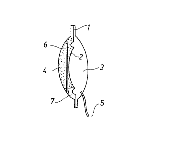
The reservoir (l) is divicled by membrane (2) lnto two
chambers (3) and (4). Chamber (3) c:ontains the medlcament, e.g.
Insulin which is in~ected into a vein or tissue through outlet
aperture (5), ln this case shown as a capilliary tube.
Propellant gas together with its liquid gas ~7) is
contained in chamber (4) whlch is hermetically sealed and
separated from the medicament ~y membrane ~2). The pressure of
ths propellant gas is only determined by the environmental body
temperature of the patient. In the case oE implanted equlpment,
a closely fitted and reliable thenmal coupling is assured.
The pressure of the propellant gas continually pres-
surizes the medicament in chamber ~3~ by means of the membrane
(2) thereby determining the quantlty of the fluid discharglng
through the outlet aperture (5). Although this action continu-
ally reduces the volume of chamber (3~ the pressure does not
change as, simultaneously, a speci~lc volume of liquid gas
evaporates to correspondlngly increase the volume of the pro-
pellant gas. The body temperature thus maintains the system in a -
static condItion relative to the yas pressure.
The possibillty to increase the dosage is, achieved in
this invention by the ralsing o~ the gas pressure. This ls achl~
eved by the induction coil ~fi~ shown in Figures 1 and 2, which i5
located directly in the regio~ of the propellant gasillquid gas
- 6 -
,~
. . ...
.
: : . ~, ~
.
:
:
t7).
It is essential that such an induction coll (6) can be
energized in the simplest way from an external source so that in
its short-circuited condition it functions as a heating coil. In
this fashion the temperature of the gas and thereby the gas pres-
sure and subsequently the in~ected fluid quantity can be increa~
sed.
For safeiy reasons, lt must be assured that an over-
dose, caused by incorrect handllng or mal~unction, cannot occur.
Thls ls achieved by the thermistor (l~) whlch ls fitted into the
induction coil (6) circuit. Naturally other solutlons are pos-
sible, e.g. thermostatic contact which breaks the circult at a
specific predetermined temperature.
The energy ls advantageously supplied by a portable
control devlce ~9) which contains ~ primary coil (10) as in a
transformer. This primary coil (10) can be either connected to
the mains circuit, or~ to make it independent of mains supply,
battery (20) powered via an alternator (21). This makes lt pos-
sible to work with the higher freguency of alternating current to
achieve a better coupling with the induction coil.
Figure 3 also shows as an example, a form of layout of
the programme controller (11) which permits ad~ustment of the
duration and/or amplltude of the induced voltage. Depending on
the reguired dosage one or the other can be more economic.
3~ FigurP 4 shows, in a guantity/tlme graph the respectlve
induced Insulin guantities in nanoliter~ over a time-base "t". A
constant quantlty (13~ is injected without interference, if, at
iime-point ~12), e.g. 12.~0 hrs., an extra dose is required, the
dosags can be increased to that shown at ~14). Depending on the
layout of the dosage device, a longer or shorter cooling time
resulis which again corresponds to regular dosage curves (15) or
- 7 -
,
` ~ :
.... ...
,
; ~
;: . ' ~ : .
~16).
A greater ampl1tude or induced voltage, or longer dura-
tion corresponds to an increased heating effect and therefore to
an extra dosage quantity (17) as shown in dosage curve (18).
A corresponding course o extra dosage is also possible
as t~me-point (l9) e.g. ls.oo hrs. as shown in Figure 4~ Such an
extra dosage could not only be administered by hand, but also by
the layout of the invented dosage device and the control device.
A sequence programmed by a doctor for permanently installed con
trol devlces, is provided for.
The specified layout examples are in no way to be seen
as a restriction. The refarences to the numerous variations by
the alteration of the single parameters permit an exact adapta-
tion to the respective given requirements~
The following Examples are mentioned:
- Adaptation of the coil windings of the primary coil (10) and
induction coil (6)
- Regulation of the duration and/or amplitude
- Sizing of the heat trans~er from propellant gas chamber ~4) to
the surrounding tissue
- Limiting of the ma~imum heat temperature and other parameters
In Figure 5, a further form of layout of the dosa~e
device according to the invention is shown. The dosage device is
implanted in the body (30) and, to record the level of blood
sugar, a sensor (23) is provided which is cnnnected to the con-
trol device ~9a) by WiriQg ~ 24 ~ .
~ -- ~ --
The control device can be permanenkly programmed, or,in a further form of layout changes to the parameters can be made
by use of the input keyboard (22).
The alternator (21) is controlled, through the wiring
(25) by the control device (9a) which controls, as required, the
amplitude or impulse. The alternator (21) creates~ together with
the primary coil ~lOa), the primary circuit ~29) which is coupled
to the secondary circuit ~6)(8) in the dosage device by the
inductive coupling (26).
As described, a self-monitoring ad~ustment of the dos-
age of long-term medicaments depending on the blood sugar level
in the body ~30) is given.
Irl Figure 6, a further form of layout is illustrated
which shows an energy-independent secondary circuit, which is a
part of the body-implanted dosage device. The induction coil ls
no longer re~uired, rather the coll used in ~he short-circuited
circuit forms the heat generator t6a), which together with the
regulator (~7) a battery (~8) and the thermistor ~8) is a part of
the secondary circuit.
The regulator ~27) is controllable outside the body,
with or without wlring by a suitable sensor (23), where~y this
sensor again records the levsl of the blood sugar in the body~
In this fash-lon an intercorporal or e~tracorporal programming of
the regulator (~7) through the blood sugar recording sensor ~23
is possible. As speclfied, the wiring ~31) can be formed as ~n
inductive coupllng or an an electrical conductor.
Figure 5 illustrates a ~urther variant of a form of
layout usi~g the connection (32) between the sugar probe ~2) and
the dosage device (1)~3)~4j. In this variant the wlring t24) to
the control device (9a) is dispensed with. The sugar probe (233
influences the re~ulator ~27) in heating circuit (6)~8) (Ref.
_ g _
.
: , . . .
Fig. 4) in such a fashion that at all times only the physiolo-
gically efficient and necessary quantities of the long-term
medicament is r~leased into the body (30~, even if, externally,
frorn the primary circuit (29) and control device (9a) the
administering of a larger quantlty of medicament is called for.
This internal control creates a self-monl-toring l~mitation of the
dosage of the long-term medicament to a physiologlcally safe
level.
In Figur0 6 yet a filrther layout variant is possible in
that inductive energy e.g. through the lnductive coupling ~26)
(Ref. Fig. 5) is transmitted to the secondary circuit ~ 33 ) Erorn
outside the body (30) either to recharge the battery (28) or to
programme the control device (27) without contact.
In the layout example in Figure 7, a rniddle chamber
consisting o* two chambers (34)(~3) is fitted in bet~een chamber
(4) containing the liquid gas propellant (9) and chamber (3)
containing Insulin. This middle chamber serves as a dosage
device between chambers (33 and (4). Both chambers (35) and (43)
are preferred filled with a low-viscosity fluld such as water.
The left limit of the chamber ~ 35 ) is formed by the flexible
membrane (2) whila the rlght limit is formed by a ri~id, non-
deflecting partition (36). Analgously, the left limit of the
right hand chamber ~43~ is formed by the rlgld partltion (36) and
the rlght hand llmit of thls chamber (43) is formed by a further
flexible membrane (41) which is essentially of the same construc-
tlon as membrane (2) and performs the same function. In the
partltion ~36) a non-return valve (31) is fitted, which in the
illustrated layout example is shown in schematic form as a valve
flap (39), whereby the non-return valve (37) is closed off in
arrow directlon ~40) for all fluld flow, but ~llowing fluid
transfer from chamber (43) to chamber ~34). ~urther a choke bore
(38) is provided in the partit1On ~36) whlch is shown in the
lllustrated exampl~ layout to he located in the valve flap ~39)
for the sake of simplicity. This choke bore could, however, be
-- 10 --
. ~,7
~,~
. ~
,
.. ~ .
.
located away from the valv~ flap (39), in the rigid partition
(36).
On the other side of the membrane (41) the chamber (3)
containing the medicament e.g. Insulin (42) ls located, in which
is the outlet aperture (5) through which the medicament is in~ec-
ted into the body tissue.
The propellant gas and the liquid propellant gas con-
tinually pressurize membrane (2) ~mder the influence of the bodytempPrature resulting in a constant in;ection of the medicament
into the body tissue. To achieve an ad~ustment of the quantity
o~ the in~ected medicament dependent on other physiological para-
meters, a temperature increase of between 10 and 20 Celsius in
chamber (4) is enough to creake a suf~icient vapour pressure
increase of the liquid propellant gas (7). As 500n as the induc-
tio~ coil (6) in chamber (4) heats up the vapour pressure of the
llquid propellant gas (7) increases and acts on the fluld ~35~ in
chamber (34) through ~he self-deflecting membrane (2).
2~
This fluid ~35) is then transferred through the choke
bore (38~ in the direction of arrow (40~ into chamber ~43) thus
expanding the volume of this chamber thus deflecting the membrane
(41) outwards and forci~g thP Insulin ~42) in chamber (3) out of
the outlet aperture (5). Depending on the type, gauge and pro-
filing of the choke bore (38), therefore, an e~actly deflned
precise quantity of Insulin ~42) is dlscharged from chamber (3)
through the outlet aperture (5). It is therefore u~necessary to
fit a ~urther restrictor in the outlet aperture. A similar
restrictor was the previously mentioned capilliary tube.
To refill the chamber (3) with medicament e.g. Insulin
( 42 ) a hollow needle is introduced into arl elastic plug (44j
through the body tissue. This action deflects the membrane (41)
in the opposite direction to that previously described and the
previously mentioned non-return valve (37) provided in the par-
I~.r
; .,,
, '
-:
.
.
tltion (36) permits a rapld return deflection of membranes (41)
and (42), so that tne fluid (35) contained in chamber (433 flows
rapidly -through the open non-return valve (37) into chamber ~34)
which simultaneously deflects membrane (2). Subsequent to refil-
ling, the equipment is available for a new service cycle.
- 12 -
.:.i.
.
. ,., ~ :
. . ,