Language selection

Search

Patent 1263005 Summary

Third-party information liability

Some of the information on this Web page has been provided by external sources. The Government of Canada is not responsible for the accuracy, reliability or currency of the information supplied by external sources. Users wishing to rely upon this information should consult directly with the source of the information. Content provided by external sources is not subject to official languages, privacy and accessibility requirements.

Claims and Abstract availability

Any discrepancies in the text and image of the Claims and Abstract are due to differing posting times. Text of the Claims and Abstract are posted:

  • At the time the application is open to public inspection;
  • At the time of issue of the patent (grant).
(12) Patent: (11) CA 1263005
(21) Application Number: 519053
(54) English Title: INJECTION MOLDING MACHINE
(54) French Title: MACHINE DE MOULAGE PAR INJECTION
Status: Deemed expired
Bibliographic Data
(52) Canadian Patent Classification (CPC):
  • 18/703
(51) International Patent Classification (IPC):
  • B29C 45/64 (2006.01)
  • B29C 45/27 (2006.01)
  • B29C 45/32 (2006.01)
(72) Inventors :
  • KAADEN, HANS-HEINRICH (Germany)
(73) Owners :
  • KAADEN, HANS-HEINRICH (Not Available)
  • STUBBE G.M.B.H. (Germany)
(71) Applicants :
(74) Agent: SWABEY OGILVY RENAULT
(74) Associate agent:
(45) Issued: 1989-11-21
(22) Filed Date: 1986-09-25
Availability of licence: N/A
(25) Language of filing: English

Patent Cooperation Treaty (PCT): No

(30) Application Priority Data:
Application No. Country/Territory Date
P 35 34 254.4 Germany 1985-09-26

Abstracts

English Abstract


ABSTRACT OF THE DISCLOSURE


There is provided an injection molding machine for the
manufacture of plastic parts from thermoplastic, thermoset
and/or elastomer material by injection molding or reaction
injection molding. The machine includes a multi-station
locking unit of horizontal or vertical configuration designed
to hold a number of molds and an injection unit associated
therewith for the simultaneous injection of the molds. The
machine also includes two outer mold clamping plates, one of
which is mounted on guide elements and movable thereon in the
locking direction and a center mold-receiving part movably
mounted on guide elements between the two mold clamping plates
and having a heatable melt conduction system with sprue nozzles
and one half of a mold attached to each of its sides. The
center mold-receiving part is designed as a mold clamping plate
sectioned lengthwise relative to the locking direction for
receiving larger halves of a mold, the two parts of the plate
being kept together by a high-speed clamping device and having
the melt conduction system mounted between each other.
Separate driving cylinders are attached to the center mold
clamping plate. The melt conduction system has one or a
plurality of separate melt conduction rails, each of which is
rigidly clamped at its face side lengthwise relative to the
direction of flow between the sectioned mold clamping plate so
that uniform injection of both molds is assured regardless of
expansion of the melt conduction system during heating.


0358K


Claims

Note: Claims are shown in the official language in which they were submitted.


The embodiments of the invention in which an exclusive
property or privilege is claimed are defined as follows:
1. In an apparatus for the manufacture of plastic parts
from thermoplastic, thermoset and/or elastomer material by
injection molding or reaction injection molding, said apparatus
having a multi-station locking unit of horizontal or vertical
configuration adapted to hold a number of molds, an injection
unit associated therewith for the simultaneous injection of the
molds, two outer mold clamping plates, one of which is mounted
on guide elements and movable thereon in the locking direction,
a center mold-receiving part movably mounted on guide elements
between the two mold clamping plates and having a heatable melt
conduction system with sprue nozzles and one half of a mold
attached to each of its sides, the center mold-receiving part
being adapted as a mold clamping plate sectioned lengthwise
relative to the locking direction for receiving larger halves
of a mold, the two parts of the plate being kept together by a
high-speed clamping device and having a melt conduction system
mounted between the parts, and separate driving cylinders
attached to the center mold clamping plate, the improvement
comprising:


said melt conduction system having at least one melt
conduction rail, each said at least one melt conduction rail
being rigidly clamped at its face side lengthwise relative to
the direction of flow between the sectioned mold clamping plate.
-7-


2. The apparatus according to claim 1, comprising a
plurality of separate melt conduction rails.


3. The apparatus according to claim 1, wherein each of
said at least one melt conduction rails is designed as one
piece.


4. The apparatus according to claim 1, wherein each of
said at least one melt conduction rails has a central melt
conduit.


5. The apparatus according to claim 1, wherein counter
opposed melt distributors are mounted in said at least one melt
conduction rail.


6. The apparatus according to claim 5, wherein at least
two pairs of melt distributors are mounted.


7. The apparatus according to claim 1, wherein each of
said at least one melt conduction rails has an outer flange on
each of its two face sides, each of said flanges being
associated with a guide coupling supported in the sectioned

mold clamping plate.


8. The apparatus according to claim 7, wherein said guide
couplings extend across the width of the sectioned mold
clamping plate and are connected thereto.
-8-


9, The apparatus according to claim 7, wherein the outer
boundaries of said flanges are approximately aligned with the
inner boundaries of the sectioned mold clamping plate.


10. The apparatus according to claim 9, which further
comprises a median centering collar arranged on the face side
of the melt conduction rail for receiving the nozzle system.


11. The apparatus according to claim 4, wherein said melt
conduit of the said at least one melt conduction rail has a
widened melt inlet.


12. The apparatus according to claim 11, wherein said melt
inlet has rounded side walls.


13. The apparatus according to clam 1, which further
comprises threaded bores arranged on the face side of the melt
conduction rail for connecting the latter with the nozzle
system.

14. The apparatus according to claim 1, wherein each said
at least one melt conduction rail is rigidly connectable with
the nozzle system on its face side.


15. The apparatus according to claim 1, wherein said
nozzle system is fastened and locked on the sectioned mold
clamping plate via a high-speed clamping device.
-9-

16. The apparatus according to claim 1, wherein a band
heater is mounted on the outer surfaces of each said at least
one melt conduction rail.


17. The apparatus according to claim 16, wherein each band
heater may be separately heated and adjusted to the appropriate
operating temperature.


18. The apparatus according to claim 5, wherein a curved,
in the direction of flow, melt feeding conduit leading to the
sprue nozzles is arranged in each melt distributor.


19. The apparatus according to claim 18, wherein a
pressure plate is arranged on the outer side of each melt
distributor.


20. The apparatus according to claim 19, wherein said
pressure plate extends flush with the outer side of the at
least one melt conduction rail.


21. The apparatus according to claim 20, wherein said
pressure plate has a bore with a diameter matching the end
diameter of said curved melt feeding conduit of the melt

distributor.


22. The apparatus according to claim 5, wherein the
contact surfaces of the sprue nozzles can be closely pressed
against the pressure plates of the melt distributors.
-10-


23. The apparatus according to claim 16, wherein said band
heater is interrupted in the neighborhood of the contact
surfaces of the nozzles.


24. The apparatus according to claim 22, wherein the outer
side of the pressure plate is slidably guided on the contact
surface of the nozzle.


25. The apparatus according to claim 1, wherein guides are
arranged on the inner side walls of the sectioned mold clamping
plate, in which the melt conduction rail is height adjustable.


26. The apparatus according to claim 1, wherein a separate
screw unit is associated with each melt conduction rail.
-11-
Description

Note: Descriptions are shown in the official language in which they were submitted.


s


The present invention relates to an
apparatus for the manufacture of plastic parts from
thermoplastic, thermoset and/or elastomer material by
lnjection molding or reaction injection molding.
Such an apparatus includes a multi-station locking
unit of horizontal or vertical configuration for
receiving a number of molds and an associated inject-
ion unit for the simultaneous injection OL the molds.
The apparatus further includes two outer mold clamp-
ing plates, of which one plate is mounted on guideelements and movable thereon in the locking
direction, and a center mold-receiving part movably
mounted on guide elements between the two mold
clamping plates and having a heatable melt conduction
system with sprue nozzles and one half of a mold
attached to each of its two sides. The center
mold-receiving part is designed as a mold clamping
plate divided lengthwise to the locking direction for
receiving larger halves of a mold, the two parts of
the plate being kept together by a high-speed clamp-
ing device and having the melt conduction system
mounted between the two plate parts. Separate
driving cylinders are attached to the center mold
clamping plate for driving the two parts.

The injection molding machine described
above permits a very economical man~]fac~llre oE larger
parts, in particular automobile body parts made of
plastic by injection molding or reaction injection
molding. By releasing the high-speed clamping

~;300X


device, both parts of the sectioned center mold
clamping plate can be displaced sideways, each with
one half of the mold, which completely exposes the
melt conduction system and renders the 1atter access-
5 ible on both sides.

During feeding of the melt, considerable
; expansion occurs in the heated melt conduction
system.

The object of the present invention is to
provide an injection molding machine as described
above having a melt conduction system wherein rapid,
uniform and simultaneous injection of both molds is
assured with any shape of mold in spite of the
expansion of the melt conduction system caused by
heating.

The above object is accomplished according
to the present invention by providing a melt con-
duction system that has one or several separate melt
conduction rails each of which is rigidly clamped at
its face side between the divided mold clamping plate
lengthwise relative to the direction of flow of the
melt. Preferably, each melt conduction rail is
designed as one piece and has a central melt conduit.

~ 3~ 5

According to another feature of the 1nvention, the melt
eonductlon rall has an outer 1ange vn each of its two face
~ides and a gulde coupling supported in the sectl.oned mold
clamping plate is assoclated wlth each flange and
advantageou ly extends acro~s the width of the sectioned mold
clamping plate. Appropriately, a median center1ng collar
adapted to hold the nozzle sy~tem i~ mounted on the face side
o~ the melt conduction railp and the melt conduit of the melt
conduction rail has a wldened melt inlet, which may have
rounded walla.


The desl~n accordlng to the pre&ent invention prov~de~ for
the po~ibllity of mounting the melt conduction rails of the
melt conduction ~ystem for feeding t.he melt at an~ deslred
polnt of the sectioned mold clamping plate, whereby a
unilateral expansion is precondltioned by fixLng the face side
of the melt conduction rail. In this connection, the des1gn
according to the invention en~ures that the pressure plate i8
~lidably guided wlth lt~ outer side on the eontact ~urface of
the no~zles, BO that the contact ~urface~ of the sprue nozzle~
and the bores of the pressure plate are centrally supported
relative to each other In each case. An expansi.on of the melt
conduction rail away f~om the sec~loned mold clamplng plate i R
prevented because the nozzle system i~ placed on the melt inlet.


Other ob~ect~ and featu~es of the present inventlon will
become apparent f~om the followi.ng detailed de~cription

con~ldered in connection with the accompanying drawing. It i~


to be under~tood, however, that the drawir.g i.s deslgned as an
iilu~tration only and nvt as a deflnition of the limits of the
invention.


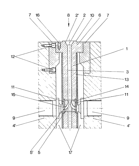
The drawlng i8 a vertical croRs~sectional view ~hrough part
oP a melt conduction rall according to the present inYention.


Melt conduction rail 1 shown ln the drawing has a central
melt conduit 3 and ls deslgned a~ one pi.ece. At its face slde,
melt conduction rall 1 has an outer flange 6 on both side~. A
guide coupllng 7 supported in the sectiQned center mold
clamping plate 4' is as~ociated with each of said flanges,
whereby the outer boundaries of the flange~ 6 are approximately
fluRh with the lnner boundaries of the ~ectl~ned center mold
clamping plate 4' r Thl~ deslgn results ~n intermediate space
17 ~hown in the figure between mold clamplng plate 4' and melt
conductlon rail 1. Because melt conduction rail 1 is rlgldly
clamped to flange~ 6 at lts face slde between center mold
clamplng plate 4' vla guide coupllngs 7, a fixed point i8
establi6hed from which melt conduction rall 1 can only expand
to one slde due to heatlng. The fact that melt conductlon rail
1 i.~ rigidly connected at lt~ face slde wlth the nozzle ~y~tem
contributes to Ruch untlateral expansion and excludes any
expansion o melt conduction rall 1 ln the opposite direction,
that is, away from the mold clamplng plate.


Melt conduction rail 1 with its opposing melt distributor~
5 is d~mensloned in such a way that taking into account


~26;~ 5

expan~ion that is expected due to heating under operatlng
condition~, it ls assured that contact ~urfaces 14 of sprue
noæzle~ 9 and bores 15 of pressure plates 11, whlch are
arranged on the outer side of melt distributors 5, are
supported centrally relative to each other in each ca~e even if
several pairs of melt distributor3 5 are mounted one on top of
the other. Contact ~urfaces 14 of sprue nozzles 9 can be
clo~ely pressed against pre~sure plate~ 11 of melt di~tributor~
5.


In this embodiment, pressure plates 11 are disposed flush
wlth the outer s1de of melt conductl~n rail 1. ~ore 15, which
i~ present in each pressure plate 11, has a dl~meter which
con~orms to the end diamete~ of melt conduit 5' in m~lt
di~tributor 5. Melt conduLt 5' is curved in the directlon of
flow, which assures a low-friction, smooth flow of the melt.


Guide coupling~ 7 extend across the width of divided mold
clamplng plate 4' and are connected w~th the latter by means of
screws 12. This permit~ a coupl1ng po~ition of indivldual
conduction rails 1 at any point with~n mold clamping plate 4'.


~ or the uptake oE the nozzle sy~tem, a median centeeing
collar 10 i9 arranged on the face si.de of each melt conductlon
rail 1. Melt conduit 3 of melt conduction rail 1 has a widened

melt inlet 2 wi.th rounded .side walls 2to The nozzle ~ystem i~
driven into this widened melt inlet 2. ~eference numeral 16
denotes a threaded bore on the face side of melt conduction
rail 1, which serve~ to connect the bore with the nozzle system.


a ~
A ~and hea~er 13 i5 mollnted on ~he outer surfaces o~ the
mel~ conductlon rail 1, which c~n be ~eparately heated and
adju~ted to the appropriate operating temperature. 8and heater
13 is interrupted in the neighborhood of no~zle c~ntact
surfaces 14 so as to assure a trouble-free vertical movement o
melt conduction rail 1. When the latter expands, pres~ure
plate~ 11 side on the noz~le contact surface~ 14 wlth thelr
outer side~. Arrow 8 i.ndlcates the directl.on of flow of the
melt.


The nozzle ~ystem placed on the melt inlet, which sy~tem i~
appropriately fa~tened and locked on sectioned mold clamping
plate 4' via a high~speed clamping device, remalns rgid~y
conneoted with the mold clamping plate under any operating
conditions and prevents expansion of melt conduction duct 1
away from mold clamplng plate 4'.


Whlle only a single embodiment of the preqent inventlon ha~
been shown and de~crlbed, 1~ wlll be obvlous th~t many change~
and modification~ may be made thereunto wlthout depart~ng from
the spirit and scope o the invention.


-6-

Representative Drawing
A single figure which represents the drawing illustrating the invention.
Administrative Status

For a clearer understanding of the status of the application/patent presented on this page, the site Disclaimer , as well as the definitions for Patent , Administrative Status , Maintenance Fee  and Payment History  should be consulted.

Administrative Status

Title Date
Forecasted Issue Date 1989-11-21
(22) Filed 1986-09-25
(45) Issued 1989-11-21
Deemed Expired 1992-05-23

Abandonment History

There is no abandonment history.

Payment History

Fee Type Anniversary Year Due Date Amount Paid Paid Date
Application Fee $0.00 1986-09-25
Registration of a document - section 124 $0.00 1987-01-08
Owners on Record

Note: Records showing the ownership history in alphabetical order.

Current Owners on Record
KAADEN, HANS-HEINRICH
STUBBE G.M.B.H.
Past Owners on Record
None
Past Owners that do not appear in the "Owners on Record" listing will appear in other documentation within the application.
Documents

To view selected files, please enter reCAPTCHA code :


To view images, click a link in the Document Description column. To download the documents, select one or more checkboxes in the first column and then click the "Download Selected in PDF format (Zip Archive)" or the "Download Selected as Single PDF" button.

List of published and non-published patent-specific documents on the CPD .

If you have any difficulty accessing content, you can call the Client Service Centre at 1-866-997-1936 or send them an e-mail at CIPO Client Service Centre.


Document
Description 
Date
(yyyy-mm-dd) 
Number of pages   Size of Image (KB) 
Drawings 1993-09-15 1 34
Claims 1993-09-15 5 150
Abstract 1993-09-15 1 44
Cover Page 1993-09-15 1 16
Description 1993-09-15 6 221
Representative Drawing 2001-04-23 1 27