Note: Descriptions are shown in the official language in which they were submitted.
29 ~
Title_ SURGICAL CLOSURE ELE~ENT_ _ __
BACKG~OUND OF THE INVENTION
This invention relates to an improved surgical
wound closure element. The improvement allows for the
sequential motion without jamming, of a plurality of closure
elements in a feed track. In the feed track, the legs of an
element are adjacent the crown of a preceding element. This
invention specifically relates to a feed track containing
two or more surgical wound closure elements. The invention
can be useful in a ligating instrument containing a plural-
ity of ligating clips and is useful in a surgical stapler
containing a plurality of staples.
This invention decreases the frictional resist-
ance between the plurality of closure elements and the feed
track. An advantage of this is that the force required to
linearly move a plurality of closure elements in the feed
track is reduced. Another advantage is that a greater number
of closure elements can be loaded into a surgical cartridge
or magazine.
The improvement to the closure element cartridge
enables the use of a very thin feed delivery system. This
advantage cannot be overemphasized. Specifically, this
advantage provides greater visibility of the crimping mech-
anism, e.g. an anvil for a surgical staple or a pair of
jaws for a ligating clip, and therefore vastly improves,
if not insures, proper placement of a closure element at
the wound site.
This invention makes possible the feeding of a
~4
~n
2~3~
2 6110g-7428
pluraliky of closure elements in a surgical instrument cartrldge,
e.g. a plurality of more than about twenty, which are sequentially
ln dlrect contact with one another in a 18g ~0 crown
configuration.
According ~o the presen~ invention there is provided a
æurgical stapler of the type having a cartridge and a handle, the
Gartridge, having means for forming a staple including an anvil
and a forming blade, and a staple feed track moYably containiny a
plurality of surgical staple~ and means for biasing the staples
toward the anvil, each staple having a crown, and two opposite
side legs; and the handle having means for activatiny said iorming
means, the activating means ln said handle being cooperatively
attached to said forming means in said cartridge, the improvement
comprislng in combination the distal end of each leg of a surgical
staple contacting the crown of the adjacent preceding staple, each
staple having at least one bend in the crown such that the distal
ends of said legs of each staple in an essentially symmetrical
converging relationship, and said biasing means acts only on the
proxlmal ætaple, wheraby the plurality of s~aples are self-
aligning on the staple feed track.
The staple feed track may comprise two opposed grooves.
Conveniently the crown may have two bends which bendsmay be equidistant from the center of the crown.
~3~
- 2a - 61109-7428
DESCRIPTION OF THE DRAWINGS
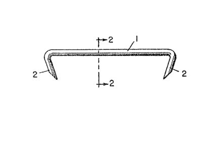
Figure l is a front view showing the legs of a wound
closure element in a converging relationship;
Eigure 2 is a cutaway sicle view taken on the
plane 2-2 of F;gure l;
Figures 3, 5 and 7 are front views showing at least
one bend in each crown oE a wound closure element and the
legs of each element in a converging relationship;
Figures 4, 6 and 8 are cutaway side views taken on
the plane 4-4 of Figure 3v the plane 6-6 of Figure 5, and the
plane 8-8 of Figure 7, respectively;
Figure 9 is a front view showing a deformation
adjacent each end of the crown of a wound closure element;
Figure 10 is a cutaway side view ta~en on the plane
10-10 of Figure 9;
Figure 11 is a cutaway front view of a surgical in-
strument cartridge showing a plurality of wound closure ele-
ments, the distal end of each leg of a wound closure ele~ent
contacting the crown of the adjacent preceding element; and
Figures 12 to 14 are alternative embodiments to the
plurality of wound closure elements shcwn in Figure 11.
DESCRIPTION
A column of two or more wound closure elements being
sequentially moved in a leg to crown fashion can employ this
invention. The amount of convergence in the legs either inde-
pendent of or combined with the amount of bend in the crown,
can vary.
A bend in the closure element crown is not nec-
essary, see for example Figures 1, 2, 9, 10 and 14, if the
closure element le~s can be otherwise deflected inward so they
do not ride onto the arc between each end of the crown and each
leg.
Side thrust is a component of forward thrust. It is
created when one of the distal ends of a leg moves laterally.
For a particular closure element, the side thrust is in direct
poroportion to the forward ~hrust. Side thrust can be cal-
culated-as a function of the imbalance between the two instan-
taneous slopes experienced by the distal ends of each leg (the
slopes are relative to a plane which is perpendicular to the
direction of the desired forward motion).
-- 4
Side thrust by a closure element causes resistance
to the forward motion of the column of closure elements. This
is due to the friction between the closure element and the
walls of the cartridge (or magazine) ~racks. The amount of
friction is the product of the side thrust multiplied by the
coefficient of friction between the closure element and the
tracks.
The force required to move the column of closure
elements ? as seen by any particular closure element, is in-
creasing by the side thrust multiplied by the coefficient offriction. Since the side thrust is in direct proportion to the
forward thrust, each closure element closer to the force
necessary to move the column of closure elements, is resisting
forward motion more than the preceding closure ele~ent. This
is due to the increased forward thrust received. The total
frictional loss of the column of closure elements in the
cartridge tracks is the sum of the frictional losses of each
closure element. When the total frictional loss is greater
than or equal to the force necessary to move the column of
0 closure elements, the most distal closure element cannot move.
Due to the above described exponential reaction
possible with a plurality of closure elements, it is desirable
to relieve the source of side thrust. One way to do this is
to use closure elements whose ends are conv,rging toward each
other sufficiently so that they contact only a flat area or
balanced slopes on the preceding closure element crown. Pro-
viding a bend to the preceding crown is one way of doing this.
Providing a deformation adjacent each end of each closure
element crown, such as notches, dents, steps or similar means
for guiding is also a way. Relieving the source of side thrust
allows more closure elements to be contained in a cartridge.
The term wound closure element is intended to be
generic and includes, but is not limited to, a staple, clip,
clamp, fastener, pin, or a similar closure element. A surgical
staple is preferred. The wound closure element exemplified in
Figures 1 to 14 is a surgical staple.
Referring to Figures 1 to 10, a surgical wound
closure element has a crown 1. Two opposite side legs 2
~ 3~ ~
are contained at each opposite end of the crown 1. The
improvement of this invention comprises the distal ends of the
opposite side legs 2 of each element being in an essentially
converging relationship (Figures 1 and 2); at least one bend
3 in the crown (Figures 3 to 8 and 11 to 13); and a deformation
4 adjacent each end of each crown 1, the distal end of each leg
2 of an element contacting the respective deformation of the
preceding element (Figures 9, 10 and 14).
The direction of the bend 3 can be in the direction
of each side leg 2. The bend enables at least the distal ends
of the legs 2 of each element to be in an essentially converg-
ing relationship.
Referring to Figures 3 to 6, 11 and 12, two bends 3
are essentially equidistant from the center of the crown 1.
lS Referring to Figures 7, 8 and 13, the bend 3 is
essentially at about the center of the crown 1. Referring to
Figures 5 to 8, 12 and 13, the notches 7 are about equidistance
from the center of the crown 1. The notches, which are
optional, can be used as a stop by the distal ends (which can
be pointed) of an adjacent wound closure element.
Referring to Figures 3, 5, 7 and 11 to 13, the bend
3a on the underside of the crown 1 can be formed during the
manufacture of the bend 3. It is to be understood that the bend
3a is not critical to the practice of this invention. That is,
alternative wound closure elements may be manufactured having
an essentially triangular shaped crown, wherein the lower
portion of the crown is essentially planar.
Referring to Figures 9, 10 and 14, an alternative
wound closure element is described. The wound closure element
has a crown 1 and two opposite side legs 2. The improvement
comprises a deformation 4 at about each end of the crown 1. At
least the distal ends of each leg 2 can also be in an
essentially converging relationship.
Referring to Figures 11 to 14, a surgical cartridge
5 is disclosed. The cartridge comprises a plurality of wound
closure elements. The elements shown in Figures 11 to 14 are
essentially a plurality of the elemen~s shown in Figures 3, 5,
7 and 9, respectively.
;3 2~3
- 6 - 61109-7428
Each wound closure element comprises a crown 1 and two
opposite side legs 2. The relation.shlp of each wound closure
element to the adjacent eleme~t in the.cartridge is a point to
crown relationship. Tha-t is, at least the distal ends of the legs
(which can be point.ed) of a wound closure element contact the
crown 1 of the preceding element. But for the point to crown
relatlonship, each wound closure element is in an essentially non-
contiguous relationship to the adjacent element.
Referring again to Figure 11, besides a plurality of
wound closure elements, the surgical cartridge 5 comprises a means
6 for containing at least the ends la of each crown and the proxi-
mal ends 2a of each leg. Preferably, the contacting means are two
opposite grooves. Although not shown, the cartridge 5 can also
contain means for attaching the cartridge to a surgical instrument,
and means for activating the plurality of closure elements by the
surgical instrument. The attaching and the activating means are
known in the prior art. Please see, for example, United States
Patents 4,196,836 issued April 8, 1980, 4,043,504 issued August
23, 1977, and 4,618,086 issued October 21, 1986. The improvement
to the cartridge of this invention allows the plurality.of elements
to be self-aligning in the containing means 6.
It is to be understood that the plurality of wound
closure elements described in Figures 12 to 14 can be alternatively
used in the cartridge 5 shown in Figure 11. That is, it is to be
understood that the wound closure elements shown in Figures 12 to
14 are interchangeable with the wound closure elements shown in
Figure 11.
" s
~:~63;~
- 7 - 61109-7428
In a final ernbodiment, the distal ends of the grooves 6
are adjacent to an anvil. A description of an anvil which can be
used to practice this embodiment is disclosed in the prior art, for
example the United States patents described above.