Note: Descriptions are shown in the official language in which they were submitted.
~ 3~
OIL WELL LOGGING TOOLS MEASURING
PARAMAGNETIC LOGGING EFFECT FOR USE IN
OPEN BOREHOLES AND CASED WELL BORES
This invention relates to the new type of nuclear
magnetic resonance method and apparatus which remotely
senses and detects the presence of unknown petroleum
reservoirs in geological formations and also allows
the direct measurement of significant portions of oil
and water fluid volume contained within the
reservoirs. The new method directly measures natural
paramagnetism of the formation by measurement of a new
physical "effect" called the Paramagnetic Logging
Effect (PLE).
Nuclear paramagnetism was first measured at very low
temperatures on solid hydrogen (G.B. Lasarew and L.W.
Schubnikow, Phys. Z. Sowjet, 11, p. 445, 1937). In
this experiment the sample's paramagnetism was
observed during the temperature cycling. However, for
ordinary sized laboratory samples at room temperature,
nuclear paramagnetism becomes extraordinarily feeble
and difficult to measure. Consequently, many other
experimental techniques known collectively as nuclear
magnetic resonance techniques were developed to
observe the nuclear magnetic moments of nucleons in
solids and liquids.
, ~
-2-
Nuclear magnetic resonance measurements are classified
into "continuous wave" and "pulse" methods.
Continuous wave observations of nuclear magnetic
resonance are performed using power absorption
measurements or nuclear induction arrangements (E.R.
Andrew, Nuclear Maqnetic Resonance, Cambridge Univ.
Press, N.Y., p. 34, 1955). Pulse methods, also known
as free precession techniques, have been developed in
recent years (T.C. Farrar and E.D. Becker, Pulse and
Fourier Transform NMR, Academic Press, N.Y., p.l,
1971).
Common to all these nuclear magnetic resonance
techniques are various means used to apply an A.C.
magnetic field at the Larmor frequency to the
collection of magnetic moments in a sample. All of
these techniques rely on initially producing a
coherent magnetization of the sample which moves
dynamically in time and which eventually decays due to
relaxation phenomena. This initially coherent
magnetization executes complex motion away from the
axis of the original static magnetic field.
Furthermore, this type of time varying coherent
magnetization produces large observable effects in
laboratory environment such as the production of large
A.C. voltage in pick-up coils. Independent of the
detailed experimental method used, the frequency of
the induced A.C. voltage generated is normally at the
procession frequency, or Larmor frequency, of the
magnetization appropriate for the ambient static
magnetic field present. The measurement of the
presence of this coherent magnetization is, of course,
an indication that the sample is in the condition of
resonance.
~, -sv~
It is well known that a singular nuclear magnetic
moment executes a precessional motion around a static
magnetic field. Here the nuclear magnetic moment may
be due to a single proton within an atomic nucleus
which is also called an "unpaired" proton or is the
actual vector sum of nuclear magnetic moments of the
protons, neutrons, and other particles which comprise
the atomic nucleus, hereafter referred to collectively
as nucleons. For the discussion of the motions of
lo such particles in applied A.C. magnetic fields, these
several terms may be used interchangeably. In the
normal 0.5 gauss earth's magnetic field, the proton's
magnetic moment processes at a Larmor frequency of
approximately 2.1 kilohertz. The tip of the magnetic
moment vector traces out a cone-shapad motion around
the static magnetic field. If a large number of
magnetic moments are placed in the earth's magnetic
field, similar motion ensues except that the tips of
the magnetic vectors fan out around the same cone.
The fact that some of the nuclear magnetic moments
have net components along the direction of the
magnetic field causes the sample's paramagnetism.
A microscopic description of the fluids in formation
provides the reason why these fields exhibit the
phenomenon of paramagnetism. Nucleons which are
chemically bound in hydrocarbons and water possess
magnetic moments. These moments tend to line up in
the earth's magnetic field. Consequently, the earth's
magnetic field in the vicinity of the hydrocarbons and
water in formation is increased by their presence.
Thls alteration of the strength of the magnetic field
of the earth in the vicinity of the fluids in
formation is the phenomenon of paramagnetism.
Conversely, if this alignment of nucleons in the
earth's magnetic field is caused to disappear by any
~ 3~
--4--
mechanism, then the paramagnetism of the formation
would also disappear.
Heretofore, it has been noticed theoretically that as
the conditions for nuclear magnetic resonance are
reached, the original paramagnetism of the sample is
reduced or eliminated (T.C. Farrar and E.D. Becker,
op. cit., p. 14). However, this fact has not been
used experimentally to actually measure whether the
sample has attained the conditions of the resonance.
Consequently, a new nuclear magnetic resonance method
is proposed whereby the condition of the resonance is
measured by the reduction or disappearance of the
original paramagnetism of the sample. Furthermore, it
is proposed to use this new type of nuclear magnetic
resonance method to detect the presence of unknown
petroleum reservoirs in geological formations and also
allow the direct measurement of significant portions
of the oil and water fluid volume contained within the
reservoirs. It is to be emphasized that the current
practicality of the method is directly attributed to
the enormous volume of liquid contained in a petroleum
reservoir.
There have been prior attempts to utilize standard
nuclear magnetic resonance techniques in situ and on
entire bulk petroleum reservoirs. In U.S. Pat.
#3,019,383 (1962), Russell H. Varian proposes using a
pulse type free precession nuclear magnetic resonance
technique to indicate the presence of oil. In U.S.
Pat. 3,060,371, Jonathan Townsend (1962) proposes
performing resonance experiments on unpaired
electronic moments to locate petroleum reservoirs. In
U.S. Patent 3,398,355, a pulse type nuclear magnetic
resonance experiment i8 proposed to be flown in
aircraft to locate oil deposits. All of these methods
- s -
rely on the coherent precession of magnetization after
conditions appropriate for resonance have been
obtained. Furthermore, all of these methods require
relatively large magnetic fields and are consequently
impractical.
Standard nuclear magnetic resonance methods are
currently being used to measure the properties of oil
reservoirs immediately adjacent to boreholes. See for
examples U.S. Pat. Nos. 4,035,718 (1977); 3,667,035
(1972); 3,657,730 (1972); 3,617,867 (lg71); 3,508,438
(1970); 3,483,465 (1969); 3,439,260 (1969); 3,395,337
(1968); etc. These methods are collectively described
as polarization-precession methods. Normally, a
strong magnetic field is applied to the oil bearing
formation which polarizes the nuclear moments present
into a coherent magnetization. The strong magnetic
field is then turned off rapidly. Consequently, the
freely precessing nuclear moments in the earth's
magnetic field are measured by sansing the A.C.
voltage induced in an induction coil at the Larmor
frequency. Furthermore, in U.S. Pat. #3,360,717
(1967, A.L. Bloom proposes using the envelope of the
A.C. signal from the freely precessing nuclear moments
to measure the longitudinal relaxation times sf the
fluids present and hence distinguish oil and water
based on these polarization-precession methods. The
reason that these representative techniques are used
immediately adjacent to boreholes is that the standard
magnetic resonance methods used heretofore require
applying relatively strong magnetic fields. Although
these are useful measurements, they do not directly
measure the amount of liquid petroleum available over
large volumes of oil bearing formation.
- ..
.
-6-
The current state of the art of these polarlzation-
precession logging tools is adequately described in an
article entitled "An Improved Nuclear Magnetism
Logging System and Its Application to Formation
Evaluation" (R.C. Herrick, S.H. Couturie, and D.L.
Best, 54th Annual Fall Technical Conference and
Exhibition of the Society of Petroleum Engineers of
the AIME, Las Vegas, Nevada, Sept. 23-26, 1979).
These logging tools are also called nuclear magnetism
logging tools. These tools measure the fluid content
in the formation immediately ad;acent to a borehole to
a lateral depth of only several borehole diameters.
The measurement of the fluid saturation factors for
oil and water present cannot be performed, however, if
the transverse relaxation times of the constituents
are very short. Furthermore, such fluid saturation
measurements are critically dependent on the typically
inaccurate estimations of the transverse relaxation
times of the constituents. Additives to drilling mud
are typically required to prevent the signal from the
drilling mud to obscure the results. The tools also
cause electrical transients because the polarizing
fields are turned off rapidly and consequently prevent
continuous measurements. Geometric irregularities of
the borehole adversely affect measurements of the
fluid saturation and can cause significant errors.
Local gradients in the earth's magnetic field caused
by objects such as borehole casing cause the failure
of these tools. Magnetic formations also cause the
failure o~ standard polarlzation-precession tools.
These tools require large power sources to energize
their polarization coils. Furthermore, these tools
provide no information concerning the characteristic
dimensions of the reservoir. In fact, all properties
such as the free fluid index, the longitudinal
relaxation times of the fluids, viscosity, porosity,
. ~, . . .
.
. ,, ~.
. .. ..
.~ .
:. . . - .
. . .
-
-7-
water saturation, oil saturation, and estimations of
the permeability from these measurements only apply to
regions immediately adjacent to the borehole which
penetrate the formation only several borehole
diameters.
Accordingly, an object of the invention is to provide
a new and practical nuclear magnetic resonance method
for the remote detection and direct volumetric
measurement of petroleum reserves.
lo It is yet another object of the invention to provide
new and practical nuclear magnetic resonance apparatus
for the remote detection and the direct volumetric
measurement of petroleum reservoirs.
And further, an object of the invention is to provide
new and practical nuclear magnetic resonance methods
and apparatus for the remote detection of the presence
of unknown petroleum reservoirs in geological
formations.
It is yet another object of the invention to provide
new and practical nuclear magnetic resonance methods
and apparatus which allow the direct volumetric
measurement of significant portions of the oil and
water fluid volumes contained within an oil bearing
formation.
Furthermore, it is another object of the invention to
provide new nuclear magnetic resonance methods and
apparatus which measure the oil and water content of
an oil bearing geological formation to a lateral
distance of at least 10 feet and up to 1000 feet from
the borehole.
., ~ .
-8-
still further, it is another object of the invention
to provide new nuclear magnetic resonance methods and
apparatus for remote detection and volumetric
measurement of petroleum reservoirs which contain
chemical constituents with short relaxation times,
particularly those with short transverse relaxation
times.
It is yet another object of the invention to provide
new nuclear magnetic resonance methods and apparatus
which do not require any measurement of the transverse
relaxation times of the oil and water species to allow
computation of the fluid saturation factors for oil
and water present.
Still further, it is yet another object of the
invention to provide new nuclear magnetic resonance
methods and apparatus which do not require that any
chemical additives be added to the drilling mud to
obtain accurate results.
Furthermore, it is yet another ob;ect of the invention
to provide new nuclear magnetic resonance methods and
apparatus which allow continuous measurements in time
to be performed.
Still further, it is yet another object of the
invention to provide new nuclear magnetic resonance
methods and apparatus which allow measurements of the
fluid saturation factors for oil and water even if the
borehole has geometric irregularities.
Further, it is yet another object of the invention to
provide new nuclear magnetic resonance methods and
apparatus which may operate in the presence of large
. .,
' '. ~ , .,
.
...
. t
_g_
local magnetic field gradients such as those caused by
borehole casing.
Still further, it is yet another object of the
invention to provide new nuclear magnetic resonance
methods and apparatus which which operate in magnetic
formations.
Furthermore, it is yet another object of the invention
to provide new nuclear magnetic resonance methods and
apparatus which consume little power and, in
particular, methods and apparatus which do not require
initially polarizing the oil bearing formations.
And further, it is still another object of the
invention to provide new nuclear magnetic resonance
methods and apparatus for the remote detection and
volumetric measurement of petroleum reservoirs which
also measure characteristic dimensions of the
reservoirs.
And still further it is another object of the
invention to provide new nuclear magnetic resonance
methods and apparatus which allow measurement of fluid
parameters in the vicinity of an open borehole such as
the free fluid index, the longitudinal relaxation
times of the constituent fluids, the viscosity of oil,
porosity, water saturation, oil saturation, and
estimations of the permeability over distances which
penetrate the oil bearing formation many borehole
diameters.
And further, it is another ob~ect of the invention to
provide new nuclear magnetic resonance methods and
apparatus which allow measurement of fluid parameters
in the vicinity of a cased borehole such as the free
'
,
.~. , , ';
~ , :
~ ?
--10--
fluid index, the longitudinal relaxation times of the
constituent fluids, the viscosity of oil, porosity,
water saturation, oil saturation, and estimations of
the permeability over distances which penetrate the
oil bearing formation many borehole diameters.
Figure 1 is a sectional view of one preferred
embodiment of the invention for remote detection and
direct volumetric measurement of petroleum reservoirs
appropriate for the situation in which many closely
spaced drill holes exist in an established oil field.
Figure 2 is a diagram used to describe the motion of
magnetic moments in an oil bearing formation during
nuclear magnetic resonance conditions.
Figure 3 describes frequency sweeping the A.C.
magnetic field applied to the oil bearing formation.
Figure 4 shows the decrease in the magnetic field of
the earth as the oil bearing formation is swept
through nuclear magnetic resonance.
Figure 5 shows the voltage induced in the induction
coil magnetometer due to the variation in the earth's
magnetic field as the oil bearing formation is swept
through resonance.
Figure 6 describes the qualitative nature of the
magnetic field variations for different distances
above the oil bearing formation.
Figure 7 is a sectional view of another preferred
embodiment of the invention for remote detection and
direct volumetric measurement of petroleum reservoirs
appropriate for use in an open borehole.
3J ~
Figure 8 is an illustrative diagram depicting the
dynamics of the excitation process.
- Figure 9 is a vertical profile of the change in the
earth's magnetic field on excitation ~B(T, X0 = 10
ft., Xh = 1 ft., Z) calculated for various vertical
positions Z where the excitation radius X0 is held
constant and equal to 10 feet (T= thickness~.
Figure 10 shows the calculated change in the earth's
magnetic field on excitation ~B(T, X0, Xh = 1 ft.,
Z = 0) for various excitation radii X0 where the
measurements are performed in the vertical center of
the formation.
Figure 11 shows the time required for excitation of
the formation ~t for different excitation diameters (2
X0) for a fixed magnitude excitation current of 10
amps peak-to-peak.
Figure 12 is an illustrative diagram depicting the
motion of magnetic moments during the excitation
process for a phase modulation scheme.
Figure 13 shows repetitively sweeping the formation
through nuclear magnetic resonance conditions with
period P.
Figure 14 shows the repetitive amplitude modulation of
the earth's magnetic field caused by the repetitive
sweeps through resonance with period P.
Figure 15 shows the repetitive voltage waveform
observed from an individual induction coil within the
induction coil gradiometer as the formation is
~ 3~
repetitively swept through the condition of nuclear
magnetic resonance with period P.
Figure 16 depicts one graphical method used to
separate the presence of oil and water.
Figure 17 presents an electronic circuit appropriate
for use with an induction coil gradiometer.
Figure 18 shows a block diagram of a gradiometer which
uses parallel resonated induction coils and voltage
amplifiers to measure the PLE.
Figure 19 is a sectional view of another preferred
embodiment of the invention for use in cased
boreholes.
Figure 20 is a plot of the attenuation factor vs.
frequency for low frequency A.C. magnetic fields which
are parallel to typs P-llO borehole casing.
Figure 21 shows one method for fabrication of a
magnetic gradiometer to be used inside borehole
casing.
Figure 22 is a sectional view of another preferred
embodiment of the invention where no boreholes exist
near the formation.
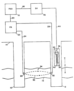
Figure 1 shows a preferred embodiment of the apparatus
for remote sensing and volumetric measurement of
petroleum reserves. This particular embodiment is
appropriate when extensive drilling has already
occurred in the oil field. Two boreholes, 10 and 12
respectively, have been drilled from the earth's
surface 14. As is shown, the boreholes have drilled
-13-
through the oil bearlng ~ormation 16. A standard
frequency sweep oscillator 18 has an output which
drives an A.C. power amplifier 22. This frequency
sweep oscillator (F.SØ) must be capable of slowly
frequency sweeping around approximately 2.1 kHz. and
the power amplifier (P.A.) must be capable of
providing significant A.C. current near the frequency
of 2.1 kHz. one output of the power amplifier is
attached to a cable 24 which is lowered into borehole
lo and is connected to a means of introducing current
into the formation 26. The other output of the power
amplifier is attached to a cable 28 which is lowered
into borehole 12 and is connected to a means of
introducing current into the formation 30. Therefore,
A.C. current is conducted through the oil bearing
formation in paths collectively identified as 32 in
Fig. 1. The total A.C. current passing through the
oil bearing formation produces an A.C. magnetic field
throughout the oil bearing strata. For example, at a
location labeled 34 within the formation, there exists
an A.C. magnetic field whose vector is primarily out
of the drawing. The magnitude of the A.C. magnetic
field but not the frequency depends on location in the
formation. The frequency of 2.1 kHz is the Larmor
freguency of protons in the nominal strength of the
earth's magnetic field of 0.5 gauss. Therefore, a
means i8 provided whereby a significant portion of the
oil bearing formation may be subjected to an A.C.
magnetic field at the Larmor frequency of protons in
the earth~s magnetic field. Furthermore, a means is
provided whereby a significant portion of an oil
bearing formation may be swept through a condition of
nuclear magnetic resonance. The significant portion
of the oil bearing formation sub;ect to the applied
A.C. magnetic field is also called the "excitation
zonQ" of the formation. As will be rigorously defined
; ,
-14-
later, this is the zone wherein the motion of the
magnetic moments become substantially affected by the
application of the A.C. magnetic field. In essence,
the excitation zone is that zone in the formation
where the application of the A.C. magnetic field
causes the paramagnetism of the fluids contained
therein to disappear or at least be substantially
reduced in magnitude.
A borehole magnetometer assembly labeled as 36 in
Fig. 1 is lowered into borehole 12 a distance Z above
the center of the oil bearing formation. In this
particular embodiment, the borehole magnetometer
assembly includes a large number of turns of insulated
wire 38 which are wound around a very high
permeability magnetic core material 40 which is in
turn connected to an amplifier 42. This amplifier
must be stable and have high gain, extremely low
noise, narrow bandwidth, and excellent low frequency
response. A relatively new integrated circuit which
is very well suited for this purpose is the OP-27A/E
(Precision Monolithics Inc., 1500 Space Park Drive,
Santa Clara, CA 95050). This operational amplifier
has a very low input noise voltage density of 5
nanovolts per square-root hertz at a frequency of 10
hertz. The required low noise and high gain are
obtained using standard electronic design principles
and several OP-27A/E integrated circuits. The output
of this amplifier is connected to a shielded cable 44
which leaves the borehole and is connected to the
input of a standard signal averager 46. The signal
averager (S.A.) obtalns its reference sync. pulse via
a cable 48 which is connected to the sync. pulse
output of the frequency swept oscillator.
Consequently, a means has been provided which measures
the low frequency variation or amplitude modulation in
3~
-15-
the earth's magnetic field. Measurements at various
positions Z provide a means whereby the variation in
the earth's magnetic field can be measured in the
vicinity of the excitation zone.
As has been briefly discussed, as matter is swept
through the condition of nuclear magnetic resonance,
it is expected that the original paramagnetism of a
sample should decrease or vanish under certain
circumstances. In this embodiment of the invention, a
means has been provided to sweep a significant portion
of the oil bearing reservoir otherwise also called an
"excitation zone" of the formation through a condition
of nuclear magnetic resonance. The application of the
A.C. magnetic field at the Larmor frequency causes a
randomization, or "scrambling," of the directions of
the nuclear magnetic moments which were initially
aligned in the magnetic field of the earth and which
in turn cause the initial paramagnetism of the
formation. This randomization process is also called
the "excitation process" of the formation and occurs
within the "excitation zone" of the formation.
Therefore, as the excitation zone of the formation is
swept through resonance, the paramagnetism of the oil
in formation is decreased or eliminated within this
zone. The paramagnetism of the excitation zone of the
oil formation contributes to the total magnetic field
measured by the magnetometer. Conseg~ently, as the
excitation zone of the oil formation is swept through
the condition of nuclear magnetic resonance, or
resonance conditions, a small decrease in the earth's
magnetic field in the vicinity of the excitation zone
is observed. This decrease in the magnetic field
strength is directly related to the volume of liquid
petroleum and water contained within the volume
defined by the excitation zone in the formation.
"~ 3
-16-
In summary, therefore, a method which has two steps is
proposed to detect the presence of unknown petroleum
reservoirs in geological formations. The first step
is applying an A.C. magnetic field at frequencies near
or including the Larmor frequency to a portion of the
oil bearing formation defined as the excitation zone
of the formation, thereby placing the excitation zone
of the formation into a state of nuclear magnetic
resonanca. This state of nuclear magnetic resonance
in turn alters the natural nuclear paramagnetism of
the formation within the excitation zone which results
in a change in the earth's magnetic field in the
vicinity of the excitation zone of the formation. The
second step is while placing the excitation zone of
the formation into a state of nuclear magnetic
resonance, measurements are simultaneously performed
detecting any change in the earth's magnetic field in
the vicinity of the excitation zone due to changes in
the natural nuclear paramagnetism of the excitation
zone to indicate the presence of absence of petroleum
and other fluids such as water within the excitation
zone of the formation.
After the initial excitation of the formation, the
nucleons then relax back along the earth's magnetic
field direction with characteristic times called
longitudinal relaxation times. The water present in
formation has a characteristic longitudinal relaxation
time (or ranges of times). This relaxation process
causes the earth's magnetic field in the vicinity of
the excitation zone to return to its prior value
before the excitation of the formation. A single
excitation-relaxation process causes a single
variation in the earth's magnetic field. A variation
in the earth's magnetic field is defined by an initial
~ J~
-17-
decrease followed by an increase in the earth's
magnetic field caused by one sweep through resonance.
In summary therefore, a method is proposed wherein the
frequency of the A.C. magnetic field applied to the
excitation zone of the formation is swept from a
frequency below the Larmor frequency to a frequency
above the Larmor frequency of the protons and other
nucleons within the excitation zone where after the
sweep through the Larmor frequency the protons and
other nucleons which have been disrupted in alignment
with the earth's magnetic field direction relax back
along the earth's magnetic field direction with
characteristic longitudinal relaxation times where the
excitation-relaxation process results in a variation
in the earth's magnetic field which is simultaneously
measured to indicate the presence or absence of
petroleum within the excitation zone.
This excitation-relaxation process may be
repetitiously repeated by suitably adjusting the
repetition rate of the sweep oscillator. The sweep
oscillator repetitiously sweeps the excitation zone of
the formation through a condition of nuclear magnetic
resonance, thereby repetitiously amplitude modulating
the paramagnetism of the formation. This excitation-
relaxation process results in a repetitive variationin the earth's magnetic field which results in an
amplitude modulation of the earth's magnetic field in
the vicinity of the excitation zone of the formation.
The amplitude modulation of the earth's magnetic field
in the vicinity of the excitation zone is measured by
the induction coil maqnetometer. As the formation is
repetitively swept through resonance, the signal
averager i8 used to increase the signal and decrease
the noise using standard experimental techniques.
3~l~ ?
-18-
In summar~ therefore, a method is proposed in which
the frequency of the A.C. magnetic field applied to
the excitation zone of the formation i~ repeatedly
swept from a frequency below the Larmor frequency to a
frequency above the Larmor frequency at such a
suitable sweep rate that the protons and other
nucleons within the excitation zone are driven into a
state of nuclear magnetic _esonance in such a manner
that substantially disrupts the orientation of the
protons and other nucleons in the earth's magnetic
field within the excitation zone and after the sweep
through the Larmor frequency the protons and other
nucleons which have been disrupted in alignment with
the earth's static magnetic field relax back along the
earth's magnetic field direction with characteristic
longitudinal relaxation times and where the
excitation-relaxation process is repeated at a
suitable repetition rate thereby resulting in an
amplitude modulation of the natural nuclear
paramagnetism of the excitation zone of the formation
which results in the amplitude modulation of the
earth's magnetic field in the vicinity of the
excitation zone of the formation and simultaneously
dêtecting the amplitude modulation in the earth's
magnetic field to indicate the presence or absence of
petroleum and other liquids such as water within the
excitation zone of the formation. Such measurements
ultimately provide the free fluid index, the
longitudinal relaxation times of the constituent
fluids, the viscosity of oil, porosity of the
formation, water saturation and oil saturation, and
estimations of the permeability of tha formation over
distances which penetrate the oil bearing formation
many borehole diameters.
... ..
'
--19--
It is now necessary to more precisely define the
conditions which result in a reduction of the
paramagnetism during resonance conditions. To do
this, some additional physics must be described. In
what follows, it is shown that there are requirements
on both the frequency sweep rate and the A.C. magnetic
field strength which depend on the physical properties
of the bulk petroleum reservoir. The following
physics is also necessary to demonstrate that the
invention provides a practical means of sweeping the
oil formation through resonance and furthermore
provides a practical means to measure the resulting
variation in the earth's magnetic field. It will be
understood, however, that the invention is not to be
specifically limited by the theory which follows.
The motion of a collection of nuclear magnetic moments
is described with reference to a coordinate frame as
shown in Fig. 2. The magnetic field of the earth is
Bo and lies along the Z axis of the coordinate frame.
An individual magnetic moment U precesses in a conic
motion around the direction of Bo in the absence of
other magnetic fields. The magnetic moment executes
this type of motion because the time rate of change of
the vector angular momentum (dL/dt) must equal the
vector torque on the magnetic moment (U X Bo)/ as
shown in Eq. 1:
dL/dt = U X Bo Equation 1.
This type of motion is described by locating the
angular position of the tip of the magnetic moment U
with respect to the X axis in Fig. 2. This angular
position is defined by the angle ~ in Fig. 2. The
time rate of change of the angle is called the angular
precession frequency wO. This angular frequency is
related to the earth's magnetic field and to the
3'~
-20-
gyromagnetic ratio of the proton ~ by the following
equation:
Wo = 7 Bo Equation 2.
As is shown in many elementary physics texts,
Equation 2 is a consequence of Equation l. Of course,
the many individual magnetic moments fan out around
the cone at different angles ~ as shown in Fig. 2.
However, the fact that the many magnetic moments have
components along the Z axis produces a net
magnetization Mz along the Z direction. This effect
of course produces the nuclear paramagnetism of
petroleum. An external magnetic field Bl is applied
to the precessing magnetic moments as shown in Fig. 2.
For simplicity only, Bl is confined to the X-Y plane,
has constant magnitude, and rotates in time through
the angle ~ which is defined in Fig. 2. In general,
Bl must only have a non-parallel component to Bo for
the validity of the following analysis (Bl must be at
a non-zero angle to Bo)~ Defining the time rate of
change of the angle ~ to be the quantity w, it is well
known that the condition of magnetic resonance occurs
when:
w = wO Equation 3.
The physical significance of resonance is that energy
may be coupled from the Bl field into the precessing
magnetic moments thus altering their motion. If the
frequency of the applied magnetic field w is swept
slowly through resonance, the solution to motion of
the vector magnetization of the sample is given by the
steady state solution to the "Bloch equations." These
equations and their solution under these conditions
are given in E.R. Andrew, op. cit., page 28.
-21-
In this analysis it is shown that the paramagnetism of
the sample may be reduced significantly or eliminated
at resonance. This phenomenon is called "saturation."
In this condition, the magnetization in the Z
direction, Mz, is reduced or eliminated. In the
aforementioned reference it is shown that saturation
occurs if the following mathematical condition is
obeyed:
~ Bl Tl T2 ~ 1 Equation 4.
In this equation, ~ and Bl have already been defined.
The quantity Tl is the longitudinal relaxation time
and T2 is the transverse relaxation time. These
relaxation times are of importance and the physical
significance that these times are of importance and
the physical significance that these times have upon
the motion of the collection of magnetic moments is
well described in T.C. Farrar and E.D. Becker, op.
cit., pages 7-15. Briefly, in this case Tl is the
time it takes for the disoriented magnetic moments to
achieve thermal equilibrium and hence realign along
the Z axis after the conditions of saturation have
been achieved. Therefore, Tl is called the thermal
relaxation time, also called the spin-lattice time.
T2 ~5 the time it takes for a hypothetical group of
magnetic moments which have been originally aligned in
one single direction in the X-Y plane of Fig. 2 to
become disoriented with their vectors fanning out and
pointing at random in that X-Y plane. T2 is also
called the spin-spin relaxation time.
If the embodiment in Fig. 1 is to be practical, the
magnitude of the A.C. magnetic field Bl (the
excitation field) as specified in Eq. 4 must not be
impractically large. Most measurements of the thermal
relaxation time Tl of crude oil in formation are known
J ,~
-22-
to fall within the following range of times (J.D.
Robinson, et al., J. Pet. Tech., 26, p. 226, 1974):
0.1 sec ~ Tl < 5 sec Equation 5.
In U.S. Pat. No. 3,395,337, R.H. Varian (1968) has
measured the following limits on T2:
10 5 sec < T2 ~ 60 sec Equation 6.
In the worst possible case corresponding to the
minimum times as specified by Tl and T2, the minimum
required strength Bl to achieve randomization of the
magnetic moments is approximately 37 milligauss.
Consequently, if an A.C. magnetic field of 37
milligauss is applied to an oil bearing formation at
the Larmor frequency, saturation will occur.
Furthermore, it is well known that most transverse
relaxation times ars longer than 10 4 sec (see Eq. 6).
This therefore would require a minimum A.C. field
strength of only 11.7 milligauss to achieve
saturation. Consequently, it has been shown that
there is a minimum A.C. magnetic field strength
necessary to produce saturation which is related to
the relaxation properties of the oil bearing
formation.
Another separate condition for the observation of
saturation is that the frequency must be swept
"slowly." This is known as "adiabatic passage." In
adiabatic passage, the change in the angular sweep
rate per unit time (dw/dt) must satisfy the following
condition (A. Abraham, The Principles of Nuclear
Maqnetism, Clarendon Press, Oxford, 19~1, p. 35):
dw/dt << ~2 B12 Equation 7.
,
....... ...
., '''' .
.
,r~ q
--23--
This equation shows that if Bl has a magnitude of 11.7
milligauss, the maximum frequency sweep rate is
approximately 100 Hz/sec. The maximum sweep rate
depends on Bl and this quantity in turn depends on the
relaxation properties of the oil formation.
Consequently, under the conditions of adiabatic
passage, there is a maximum permissible frequency
sweep rate applicable to a given oil bearing
formation.
If the above sweep rate is exceeded, other phenomena
happen which are classified as types of "fast
passage." In these cases, the magnetization of the
sample cannot follow the net magnetic field and none
of the conditions applicable to adiabatic passage are
satisfied. However, the magnetization in the Z
direction, Mz, does in fact decrease or disappear if
the following equation is satisfied (T.C. Farrar, E.D.
Becker, op. cit., p. 10-15):
1 s ~ Bl ~t ~ Bl Tl Equation 8.
In Eq. 8 the transit time through resonance ~t must
certainly be less than the longitudinal relaxation
time Tl. From Eq. 5, the minimum longitudinal
relaxation time is 0.1 second and therefore Eq. 8
specifies in this worst case that the magnitude of the
required A.C. magnetic field to cause excitation is
approximately 0.37 milligauss. This is a very small
magnetic field. For example, if an A.C. current of 10
amps (peak-to-peak) were passed through a localized
area of the petroleum reservoir, the A.C. magnetic
field produced by this current would exceed 0.37 gauss
(peak-to-peak) inside a radius of 54 meters.
Therefore, useful measurements may be performed within
the formation to lateral depths of at least 10 feet
and up to perhaps 1000 feet from the borehole.
Consequently, the invention provides a practical means
to sweep significant portions of an oil bearing
formation through the condition of magnetic resonance.
Perhaps it should be emphasized that no polarization
step is required as in the case of polarization-
precession logging tools because the preferred
embodiment has a resonant excitation process which
requires relatively small A.C. magnetic fields.
In fact, for any distribution of A.C. currents giving
rise to the A.C. magnetic field at the Larmor
frequency applied to the formation, Equation 8
indirectly defines the geometry of the excitation zone
wherein the paramagnetism of the formation becomes
disrupted due to these applied A.C. magnetic fields.
Furthermore, the size of the excitation zone may be
varied at will by simply changing the amplitude of the
A.C. current applied to the formation and the
placement of the current carrying electrodes attached
to the formation. Since the large volume of the
excitation zone can be varied at will, any signal
coming exclusively from the borehole fluid may be
isolated and therefore no chemical additives need be
added to the drilling mud to suppress the borehole
signal. For the same reasons, the signal from an
irregular borehole geometry may also be isolated and
therefore eliminated from in nuencing the estimations
of the fluid saturations in formation. And lastly,
the deep variable penetration afforded by the method
also allows systematic identification of
characteristic dimensions of the reservoix such as the
upper and lower surfaces, oil and water boundaries,
and certain varieties of gross lateral irregularities.
The invention provides a practical method of detecting
the effects of saturation and fast passage phenomena.
~ '` .
.~
~- - ' - , -. ~.
.
.3~
-25-
The paramagnetism of the oil formation gives rise to a
small increase in the magnetic field above the oil
reservoir ~B(Z). For simplicity only, it is assumed
that the resonance is due only to "unpaired protons"
(also called "hydrogen-like" or "unbound"). Near the
reservoir for typical situations and typical
excitation zones of interest:
~B(Z=0) = uOpU2 Bo/3kT ~ 1 x 10 10 gauss
Equation 9.
The quantities used in this M.X.S. equation include
the following: uO (permeability of space); p (number
of unpaired protons/M3); U (magnetic moment of a
proton); Bo (earth's magnetic field); k (Boltzmann's
constant); and T (absolute temperature). Equation 9
is derived in C. Kittel, Introduction to Solid State
Physics, Fourth Edition, John Wiley & Sons, New York,
1971, page 503.
Ideally, the small magnetic field change referenced in
Equation 9 is driven to zero during a sweep through
resonance. Consequently, the excitation-relaxation
process yields approximately a 1 x 10 10 gauss
multiple modulation in the earth's magnetic field at a
frequency of approximately 1 Hz in the vicinity of the
excitation zone. The engineering requirements
necessary to build a sensitive induction coil
magnetometer which can perform such measurements are
understood. For additional information, please refer
to the following: (1) G.V. Keller and F.C.
Frischknecht, Electrical Methods in GeoPhYsical
30 Prospecting, Pergamon Press, N.Y., p. 237, 1966);
(2) L.K. Hill and F.X. Bostick, Jr., "Micropulsation
Sensors With Laminated Mumetal Cores," Electrical
Engineering Research Laboratory, The University of
t~ ~t A ~
-26-
Texas, Austin, Texas, Report No. 126, May 25, 1962;
(3) R. Xarmann, "Optimierung des Signal/Rausch-
Verhaltnisses von Induktionsspulenmagnetometern fur
die Magnetotellurik," Dissertation, Technischen
Universitat Carolo-Wilhelmina zu Braunschweig, lg75;
and (4) W.D. Stanley and R.D. Tinkler, a U.S.G.S. open
File Report entitled "A Practical, Low-noise Coil
System for Magnetotellurics," U.S.G.S., Denver,
Colorado. The last reference cites constructing an
induction coil with a noise level of 4 x 10 10 gauss
at 1 Hz. Resonating this induction coil at 1 Hz by
suitably selecting a resonating capacitor for the
parallel RLC circuit results in significantly improved
performance. Furthermore, building a slightly longer
induction coil with more windings of heavier gauge
wire would also result in a more sensitive induction
coil. Thus, the induced voltage due to the saturation
of the excitation zone of the oil bearing formation
may be detected over the intrinsic noise present by
using known engineering techniques and by using
suitably long data integration times.
Other types of background noise may cause additional
difficulties, however. It is expected that the normal
fluctuations in the earth's magnetic field near 1 Hz
will be observable in the depths of the borehole.
Simply averaging the results for a longer period of
time using the signal averager will average those
influences to zero in time. If this longer period of
time for averaging is unacceptable, then a second
induction coil may be added a distance below induction
coil 36 in Fig. 1, thereby resulting in a gradiometer
assembly. A gradiometer used in a differential
arrangement would cancel out fluctuations in the
earth's magnetic field using standard practices in the
field of magnetic measurements in the geophysical
.
..... . .
,
'
- ~
, ' , .
~ ;3~
sciences. Care must also be taken to prevent swinging
motion of the induction coil 36 in Fig. 1 as such
motion would induce spurious signals in the induction
coil. And finally, the high permeability core 40 in
the induction coil 36 is known to be extremely
microphonic and, therefore, a stop-and-hold method may
be used to take sensitive data. A mechanism which
would lock the tool in place in the borehole would be
of considerable use if a stop-and-hold method were
used to take data. For the purpose~ of clarity,
gradiometers are also called differential
magnetometers in the literature.
Figures 3, 4, and 5 show the time dependence of the
experimental signals expected from the apparatus
embodied in Fig. 1. Figure 3 shows that the
frequency, F, of the A.C. magnetic field is swept from
a lower frequency Fl through the resonant Larmor
frequency Fo to a higher frequency F2 in a time which
must be less than the longitudinal relaxation times of
the oil and water fluids to be measured in the oil
bearing formation. At the time To~ the formation is
in the condition of nuclear magnetic resonance.
Figure 4 shows the corresponding decrease and
subsequent increase in the earth's magnetic field, B
at the time To~ This event is defined as a variation
in the earth's magnetic field. And the voltage
appearing across the induction coil, V, is shown in
Fig. 5. The excitation-relaxation process may be
repeated and as the formation is repetitively swept
through a condition of nuclear magnetic resonance the
variation in the magnetic field of the earth repeats
periodically and so does the voltage induced in the
induction coil.
;~
-28-
The precise shape of the signal in Fig. 5 depends on
the longitudinal and transverse times Tl and T2 of the
oil and water species present in the excitation zone
among other parameters such as the sweep time, etc.
However, the amplitude of the variation in the earth's
magnetic field is primarily dependent on the
longitudinal relaxation times of the fluids present
and depends little on the transverse relaxation times
of the fluids present. In general, the oil and water
phases in any one borehole have different Tl times (or
ranges of times) which allows for differentiation
between oil and water. This differentiation is
accomplished by varying the rate at which the
formation is repetitively swept through the condition
of nuclear magnetic resonance. For example, if the
water species has a shorter longitudinal relaxation
time Tl (water~ than the longitudinal relaxation time
of the oil Tl (oil) then if the repetition period T
(rep) is longer than either of these times, both the
oil and water species may relax back along the earth's
magnetic field after excitation. Consequently, in
this case, the amplitude of the voltage in Fig. 5
would reflect the sum of the signals from both oil and
water. However, if the repetition period is longer
then Tl (water) but shorter than Tl (oil), then the
oil never has a chance to relax back along the earth's
magnetic field before the next successive frequency
sweep. Consequently, in this case, the amplitude of
the voltage appearing in Fig. 5 would be coming
primarily from the water species present after the
initial first pass through resonance. In most
instances, the relaxation time or ranges of times for
the water present are shorter than the relaxation time
for the oil species present. However, if the times
were reversed in order, then obviously the oil signal
~v~
.
3~ ?
--29--
could be solely discriminated by progressively
shortening the repetition period.
Therefore, the amplitude of the variation in the
earth's magnetic field on excitation and the
longitudinal relaxation times of the field
constituents may be found by varying the period of the
periodically sweeping magnetic field. Using standard
geophysical principles, such information allows the
measurement of fluid parameters such as the free fluid
index, the longitudinal relation times of the
constituent fluids porosity, water saturation, oil
saturation, and estimations of the permeability over
distances which penetrate the oil bearing formation
many borehole diameters. Once the longitudinal
relaxation time of the oil is known, then the
viscosity of the oil may be deduced since the
viscosity is a monotonic function of the longitudinal
relaxation time. (Please see J.D. Robinson, et al.,
1974, ibid., Fig. 4, for more information.) It is
also worth noting that in typical waterwetted
formations, the oil is isolated from intimate contact
with the rock and so the distribution of relaxation
times for the oil species i8 usually small. By
contrast, any distribution of relaxation times for the
water present is possible. Furthermore, the
paramagnetic impurities present in formation are
usually relatively more soluble in water than in
petroleum and consequently this fact also contributes
to a narrow distribution of Tl times for any oil
present. In addition, analysis of the Tl
distributions for the oil and water in formation would
allow inference of many of the geometric and chemical
properties of the surrounding rock using standard
geophysical principles. Uses of Tl distributions to
-30-
infer surrounding microscopic rock structure are minor
variations of the invention.
In summary therefore, a method is proposed in which
the range of relaxation times of the fluid
constituents and the relative volumes of oil and water
in formation may be determined by suitably varying
the repetition rate which is adjusted by changing the
period of the periodically sweeping A.C. magnetic
field and simultaneously measuring the magnitude of
the amplitude modulation in the earth's magnetic
field. Furthermore, the period of the repetition rate
is initially chosen to be longer than the longitudinal
relaxation time of any of the constituent fluids of
interest in the formation and is thereafter set to
progressively shorter intervals of time such that the
period of the repetition rate is adjusted to be
shorter than any one particular longitudinal
relaxation time of any of the particular fluid
constituents of interest in formation while
simultaneously measuring the amplitude modulation in
the earth's magnetic field in the vicinity of the
excitation zone of the formation where the formation
contains a variety of constituent fluids collectively
called oil and water with ranges of relaxation times
appropriate for those constituents in formation. And
lastly, since the longitudinal relaxation times Tl are
much shorter for solids, only the paramagnetism of
liquids in formation is observed (E.R. Andrew, op.
cit., p. 151).
As previously described, the standard polarization-
precession logging tools cannot work if the transverse
relaxation times of the fluids in formation are short.
The measurements performed by the preferred embodiment
are not affected at all by short transverse relaxation
J . g ;~ A ~
-31-
times and, in fact, no information about such
transverse relaxation times of the fluids in formation
is required for the measurements of the amount of oil
and water in formation. Furthermore, large magnetic
field gradients caused by borehole casing and also
phenomena caused by magnetic formations result in
similar effects to those caused by short transverse
relaxation times and therefore the preferred
embodiment can perform measurements in such
environments.
The total fluid volume, average fluid density, and the
dimensions of portions of the petroleum reservoir may
be found from the following procedure. The variation
in the earth's magnetic field during resonance ~B(Z)
is measured for various distances Z above and below
the oil reservoir. Please refer to Fig. 6, which
shows a typical plot of ~B(Z) versus Z. Near the
excitation zone of the oil formation, measurement of
~B(Z) yields the quantity p in Eq. 9, which is the
average number of unpaired protons/M3 within the
excitation zone of the formation. Since the signal is
only from liquids, this immediately yields the average
fluid density within the formation. In region A in
Fig. 6, which is in the vicinity of the excitation
zone of the oil reservoir, the magnetic field
decreases approximately as l/z2 (R. Bunumof, Concepts
in Electricity and Magnetism, Holt, Rinehart and
Winston, N.Y., p. 196, 1961~. An inflection at
point B in Fig. 6 demonstrates that the distance Z has
reached some characteristic dimension of the oil field
such as the thickness or the average diameter of the
oil deposit. Region C shows the behavior of the
magnetic field for large Z when the paramagnetic
reservoir behaves as if it is a large single magnetic
moment UT. UT i8 of course the sum of all the
. .
-32-
magnetic moments in the excitation zone of the
formation. Equation 10 shows that ~B(Z) decreases as
1/~3 for large Z (D. Halliday and R. Resnick, Physics
for Students of Science and Enaineerinq, John Wiley &
Sons, N.Y., p. 772, 1963):
~B(Z) = T Equation 10.
4~ Z
Once UT is obtained by fitting the data, the total
number of unpaired protons in the excitation zone of
the formation may be obtained. From the known
lo chemical composition, nuclear properties, and
densities of crude oil, the free fluid volume of the
formation may be calculated. Furthermore, by
combining this information with the information
available from measurements on the longitudinal
relaxation times of the fluids in formation, the
following properties of the excitation zone may be
determined using standard techniques in the industry:
porosity, viscosity of oil, water saturation, oil
saturation, and estimations of the permeability of the
formation.
As described herein, the new magnetic resonance method
as applied to formation evaluation is fundamentally
different from any other resonance method proposed
heretofore. Consequently, the repetitive excitation-
relaxation process causing an amplitude modulation inthe paramagnetism of the formation resulting in an
amplitude modulation in the earth's magnetic field
caused by repetitively applying an A.C. magnetic field
at the Larmor frequency to the formation is a new
physical process or "effect," and it is proposed to
call this effect the "Paramagnetic Logging Effect," or
PLE for brevity.
..,
-33-
In the embodiment described in Fig. 1, electrode 26 is
shown explicitly at a position deep within
borehole 10. This was shown for the purpose of
simplicity only so that the current lines 32
approximately follow the oil bearing formation.
However, electrode 26 may be equally placed on the
surface of the earth some distance from borehole 12
which is logical extreme of allowing borehole 10 to
have zero depth. The A.C. current flowing through
formation then no longer follows the formation
laterally but instead returns to the surface via
conduction through strata separating electrode 30 and
electrode 26 which is now on the surface. The A.C.
magnetic field providing the excitation of the
excitation zone of the oil bearing formation is then
due to the A.C. current conducted down cable 28 and
the simultaneous influence of the A.C. current
conducted through the formation.
Figure 7 shows another preferred embodiment of the
apparatus for remote sensing and volumetric
measurement of petroleum reserves. This particular
embodiment is appropriate when only one borehole has
been drilled in the earth. All of the numbered
elements through number 48 has been defined in the
description of Fig. 1. These descriptions are briefly
recounted in numerical order: 12-a borehole; 14-the
earth's surface: 16-the oil bearing formation: 18-the
frequency swept oscillator (FS0): 20-output of
frequency-swept oscillator connected to power
amplifier; 22-power amplifier (PA); 28-cable attached
to one output of power amplifier which is lowered into
the borehole and attached to a means of introducing
A.C. current into formation 30; 32-current return
path; 34-a location in the oil bearing formation;
38-turns of insulated wire; 40-high permeability
~ t
-34-
magnetic core material: and 44-shielded cable carrying
output of the amplifier.
Features which distinguish the preferred embodiment
from Fig. 1 are as follows. A.C. current is conducted
into the formation by the electrode 30 at a location
far below the oil bearing formation. This distance L
below the formation is assumed to be many times the
average thickness T of the oil bearing formation. A
cable 50 connects the other output of the power
amplifier to a surface electrode 52. Surface
electrode 52 is a means by which current may be
conducted from the surface of the earth to the power
amplifier. Electrode 52 is a distance Y away from the
borehole. Therefore, a complete circuit exists for
the two outputs of the power amplifier and A.C.
current is conducted through the formation by paths
collectively identified as 32. It is evident that if
L and Y are comparable to the depth of the oil bearing
formation D, then very little of the return current
passes near the borehole. Therefore, in a region near
the borehole for a radius XO such that XO < L, then in
this region the A.C. magnetic field is primarily due
to the A.C. current conducted through the cable 28.
This A.C. magnetic field produces excitation of the
magnetic moments in a region around the borehole
identified by the radius XO. This excitation volume
is shown as a shaded region in Fig. 7 and is
mathematically defined in the text which follows.
An induction coil gradiometer 54 houses two separate
induction coils which are arranged in a differential,
subtraction or "bucking mode." Insulated wire 38
would around high permeability core material 40 is one
lnduction coil and insulated wire 56 is wound around
high permeability core material 58 thus making a
-35-
second separate induction coil. The centers of the
induction coils are separated by a distance S
resulting in a standard gradiometer arrangement.
Standard electronic design principles are used to
operate the amplifier 60 in a differential or
difference mode.
Ancillary instrumentation necessary to provide
additional measurements used to correct that data is
contained in section 62 includes but is not limited to
lo the following: (A) an instrument which measures the
inclination of the earth's magnetic field; (B) an
instrument which measures the strength of the earthls
magnetic field; (C) a thermometer which measures the
temperature of the borehole fluids; (D) a device which
senses the size of the borehole; and (E) a device
which measures the density of the borehole fluids.
Such individual devices are well known instrumentation
in the borehole geophysics industry.
A programmable control unit (PCU) 64 is connected to
the freguency sweep oscillator via cable 66. The
purpose of this unit is to control the timing between
sweep rates which iB used to separate oil and water
under various circumstances. A phase sensitive
detector 68 which is capable of measuring the in-phase
and out-of-phase signals with respect to the reference
signal provided by cable 70 attached to the sync.
pulse output of the frequency sweep oscillator is used
instead of the signal averager to provide superior
narrow-bandwidth detection of the signal. The sync.
pulse output used is the type where a TTL level
changes when a preset market fre~uency is crossed
during a frequency sweep. A Model 178 Programmable
Waveform Synthesizer manufactured by Wavetek, Inc., of
San Diego, California, provides such a suitable
,
3~ ?
--36--
waveform. A commercial example of a suitable phase
sensitive detector is the Model 5204 manufactured by
EG&G, Princeton Applied Research, Inc., Princeton, New
Jersey. Standard engineering procedures are used to
control the pressures and temperatures of the sonde.
Furthermore, standard practices are also used in the
fabrication of electrode 30 and its attachment to the
sonde .
The A.C. magnetic field provided primarily by cable 28
is applied to a region of the formation which
subsequently disorients the magnetic moments within
the excitation zone. Therefore, after excitation, the
contribution that this excitation zone originally
provided to the total static magnetic field of the
earth is removed. The subsequent change in the
earth's magnetic field produced by the excitation is
therefore the negative of the contribution to the
total static field provided by the excitation zone.
This change is, of course, measured with the induction
coil gradiometer. The following theory is
representative of the current understanding of the
excitation process for this embodiment of the
invention. It is to be understood, however, that the
invention is not to be specifically limited by the
theory which follows.
The model chosen for calculating the effects due to
the excitation of the formation is shown in Fig. 8. A
relatively thin, cylindrical-shaped oil deposit has a
radius R and a thickness T. The borehole is parallel
to the Z axis and has a radius Xh. The earth's
magnetic field Bo is at an angle ~ with respect to the
borehole. The dynamics pictured in Fig. 8 are
rigorously correct for a magnetic field which is
parallel to the borehole with magnitude Bo cos , but
-'4~;jJ~ 'q
--37--
the final results are generally true and therefore
this simplified picture is justified. An A.C.
current I is passed along the Z axis through cable 28
in Fig. 7, where I = Io cos(wO t). As discussed
before, the return current near the borehole is
negligible in this case. This A.C. current produces a
radial A.C. magnetic field Br~ where Br = Bl cos(wO
t). Since the frequency of the A.C. magnetic field is
at the Larmor frequency, wO, then any magnetic moment
U originally aligned along the Z axis is caused to
tilt away from the Z direction through the angle ~.
In the reference frame of the oil deposit, these
magnetic moments execute conic motion about their
respective locations. Several locations are specified
in Fig. 8 as Pl and P2. The dotted lines in Fig. 8
show this conic motion. The magnitude of the angle
is given by the following equation:
~ = ~ Bl ~t Equation 11.
The quantity ~ is the gyromagnetic ratio of the proton
and has a value of 2.68x10⁴ radians/(sec-gauss), and
Qt is the length of time during which the current has
the appropriate frequency for resonance.
The quantity Bl varies with the radius away from the Z
axis, X, as follows:
B (X) = Equation 12.
Consequently, the angle ~ i6 given by the following
equation:
u
~(X) ~ ~ 0 o ~t Equation 13.
, . . . .
-38-
This shows that for a given length of time ~t, the
angle ~ varies dramatically with X. In this
discussion, the variable ~t is viewed as a totally
independent variable. The reason for this etatement
is fairly evident. If a given formation has a small
variation in the local magnetic field strength, then
there is only a small frequency interval which
satisfies the Larmor condition. Therefore, the
frequency can be swept through this frequency interval
in any arbitrary time interval ~t.
As the angle ~ is increased, components of the
magnetization parallel to the Z axis are produced, and
components of the magnetization parallel to the plane
of the cylindrical-shaped oil reservoir are also
produced. It is rigorously true that, at the position
Z=0, the horizontal components of the magnetization
produced in formation by this effect make no
contribution to the axial strength of the earth'~
magnetic field. And in general, components of the
magnetization which are parallel to the plane of the
oil reservoir produce little net effect upon the axial
magnetic field. Therefore, the axial magnetic field
is primarily influenced by those magnetic moments
which have components parallel to the Z axis. The
following calculation uses the approximation that only
magnetic moments parallel to the Z axis produce any
net effect in the axial component of the earth's
magnetic field.
A calculation of the axial magnetic field for various
positions Z may be performed which integrates the
magnetic dipole contributions from each elemental
volume of magnetization which is weighted by the
factor cos ~ at each point. An "effective excitation
radius" X0 is found for a given Io and ~t where it is
,. .' ., '
., . ,.......................... , '
' ..
~"."'~ ,yL'~
found that this particular radius the contribution
from the excitation volume to the axial magnetic field
becomes zero. X0 in MKS units is given by the
following:
u
X0 Z 2~ ~t Equation 14.
For any current Io in amperes, and any time interval
~t in seconds, X0 is given in feet by the following
equation:
XO(feet) = 56.0 ampesetec Io ~t Equation 15.
The physical significance of the radius X0 is
interesting. Close to the borehole, the magnetic
moments rotate through many radians unless disturbed
by relaxation phenomena. The outer distance X0 is
that particular radius at which the moments are turned
through an angle of ~ = ~ radians. The entire volume
bounded by this radius then contributes no component
to the earth's magnetic field. Consequently, this
volume is said to have undergone "excitation."
After the excitation of a portion of the oil deposit
defined by the thickness T, effective excitation
radius X0, and diameter of borehole Xh, then the
change in the earth's magnetic field along the
direction of the borehole at a particular vertical
position Z is given by the quantity ~B(T, X0, Xh, Z),
which is given by the following algebraic formula:
~B(T,Xo,~,Z) - (uo/2) Mo cos ~ {G(T,Xh,Z) - G(T,Xo,Z)}
Equation 16.
YL k~ t~
-40-
where G(T,Xh,Z) and G(T,Xo,7) are given as follows:
G(T,Xh,Z) ~ Z + (T/2) _ Z - (T/2)
( (Z+(T/2)) 2 ~ xh2)1/2 ~ (Z (T/2)) 2 + xh231/2
Equation 17.
G(T,Xh,Z) ~ Z ~ (T/2) _ z - (T/2)
l~Z+(T/2)~ + X02~l/ l(Z-(T/2)) + XO )
Equation 18.
and where Mo~ the magnetization, is given by the
following:
N u2 Bo ~
M = Equation 19.
and where the other parameters of interest are given
by the following quantities:
= angle of magnetic field from vertical
(approximately 30 degrees in North America);
uO = permeability of space (4~ x 10 7 henrys/
meter);
N = number of protons per unit volume for pure
water (approximately 6.6 x 1028 protons/
meter3; for oil this number is only slightly
larger);
U - magnetic moment of the proton (1.41 x 10 26
amp/meter2);
Bo = static magnetic field of the earth
(nominally 0.5 gauss in North America);
= saturation factor of fluids in formation
(ranges from o.O to l.o);
k = Boltzmann's constant (1.38 x 10 23 joules/
degree Kelvin used); and
~5~ i*~ ~
-41-
t = temperature in degrees Kelvin (300 degrees
Kelvin used).
Note: conversion factor from M.K.S. units
(webers/meter2) to C.G.S. units (gauss) is as
follows: 104 gauss/weber/meter2. Equations 16
and 19 are in M.K.S. units.
Consequently, the numerical result for Eguation 16 is
as follows in the units of gauss:
~B(T,Xo,Xh,Z) - 2-9 x 10 gauss (~9){G(T,Xh,Z) - G(T,Xo,Z)}
Equation 20.
In the following graphs of the results (Figs. 9 and
10), the radius of the borehole is chosen to be 1
foot, the fluid saturation of formation hydrocarbons
(or water) is assumed to be 20%, and the earth's
magnetic field is assumed to be included 30 degrees
from the vertical, which is appropriate for much of
the U.S.
Figure 9 shows a vertical profile of the change in the
earth's magnetic field ~B(T, Xo=10 ft., Xh=l ft., Z)
calculated for various vertical positions Z where the
excitation radius is held constant and equal to 10
feet. The positive direction is along the direction
of the earth's magnetic field. The results are
plotted for three values of the thickness T=l, 2, and
10 feet. The variations in the earth's magnetic field
on excitation for small Z are affected dramatically by
the presence of the borehole, whereas for large Z they
are determined exclusively by the GUter geometry of
the excitation zone. It is evident that the
measurements are sensitive to the upper and lower
fluid boundaries.
;?
-42-
Figure 10 shows the calculated results for
measurements performed at one vertical position, Z=0,
which is located in the vertical center of the oil
bearing formation. In this case, the borehole tool
remains vertically fixed but the excitation radius xO
is progressively increased by increasing the amplitude
of the A.C. current which causes the excitation. The
results are plotted for three parameters of the
thickness, T = 1, 2, and 10 feet. This invention
provides an unusual attribute, namely the ability to
probe laterally into formation by simply increasing
the magnitude of the A.C. current conducted through
cable 28.
The minimum time reguired for excitation of a given
volume defined by the excitation diameter 2Xo is given
by Equation 15. If Io is 10 amps, which is a
reasonable current, then the minimum excitation time
~t for the cases cited is given by Fig. 11. For
example, the minimum excitation time required for a 6
foot diameter section is 0.005 seconds and the time
required for a 65 foot diameter section is 0.06
seconds. These are fast excitation times which are
shorter than almost any longitudinal relaxation time
Tl appropriate for actual oil bearing formations as
shown in Equation 5. In this embodiment, the minimum
excitation time ~t must, of course, be shorter than
the longitudinal relaxation time Tl of any fluid of
interest. In general, for a given chosen excitation
radius X0, the current Io must be chosen such that the
excitation time ~t is shorter than the longitudinal
relaxation time of the fluid being measured.
Eguations 15 through 20 provide the basis for one
method used to measure the amount of petroleum in
formation within a well defined excitation zone. If
-43-
the magnetic field varlations are measured at the
position of Z=0, then as the peak-to-peak A.C. current
is increased, the excitation radius X0 is increased
and the measurements vary according to Equation 16.
Therefore, the quantity ~B(T, X0, Xh, Z=0) versus
different xO may be obtained from the data. It is
obvious that both T and ~ may be deduced from a
mathematical fit of the results because they affect
the magnetic field variations through different
functional relationships. For example, it is evident
from Equation 16 that for the limit of X0=O, the
results for 6B(T,Xo,Xh,Z=0) are primarily influenced
by the parameter ~. And furthermore, for large values
of X0 such that X0 >> T, the results for
6B(T,Xo,Xh,Z=0) scale as T/Xo. Consequently, both
and T may be easily separated from the data.
Another method is obvious to measure the quantities of
and T. The quantity 6B(T,Xo,Xh,Z) can be measured
for various distances Z with all other quantities held
constant (particularly X0 = constant). A subsequent
mathematical fit to the data results in knowledge of
both ~ and T because these quantities affect the data
through different functional relationships. This is a
second method which independently measures both ~ and
T. Many other methods for determining ~, T, and other
desired quantities based on this theory are also
evident but are only minor variations of the preferred
embodiment.
It should be noted here that 6B(T,Xo,Xh,Z) is the net
magnetic field change from a time before excitation to
a later time after the magnetic moments have become
disoriented. It i6 the net change from before to
after the excitation time ~t. However, 6B(T,Xo,Xh,Z)
need not necessarily go to zero uniformly during the
C~3
-44-
time interval ~t. Several oscillations in time of
~B(T,XolXh,Z) may occur during the excitation time At
if the relaxation times are long compared to the
excitation time. Such oscillations are particularly
likely if T2 is much longer than the excitation time
~t. In this case, the magnetic moments are rotated
through different angles ~ radially away from the
borehole. At any one instant, for example, more
moments may be "up" than "down." In the next instant
lo more moments may be "down" than "up." As such excess
number of moments drift in and out of phase, "beating~
or oscillations in the earth's magnetic field may
occur. Such oscillations would be expected to appear
only if the magnetic field in the vicinity of the
borehole is very uniform.
The physical mechanism causing such oscillations in
the natural nuclear paramagnetism of the excitation
zone is entirely unrelated to other oscillatory
phenomena associated with various types of nu~lear
magnetic resonance measurements. In most nuclear
magnetic resonance measurements, a coherent
magnetization is prepared which precesses at the
Larmor freguency and measurements are performed at the
Larmor frequency appropriate for the magnetic moments
present. Therefore, in the usual polarization-
precession nuclear magnetic resonance methods in the
earth's magnetic field, measurements are performed at
the Larmor frequency which is at approximately 2 kHz.
In the preferred embodiment, the natural oscillations
which may occur during and after a sweep through
resonance would not appear at the Larmor frequency but
instead would appear at a frequency which is
substantially less than the Larmor frequency. The
appearance of the oscillations during and after a
sweep through resonance and their detailed character
, ", . - . , .
--45--
would depend upon the amplitude of the applied A.C.
magnetic field and the sweep rate through resonance.
The essential feature characterizing these
oscillations in the earth's magnetic field is that
they are caused by an amplitude modulation of the
natural paramagnetism of the oil bearing formation
which is caused by repeatedly applying an A.C.
magnetic field at the Larmor frequency to the
formation and furthermore these oscillations occur at
a frequency which is unrelated to the Larmor frequency
of the moments in formation. Measurement techniques
to determine ~ and T can be similarly based on these
oscillatory phenomena as well. Measuring the
amplitude and phase of such oscillations in the
natural nuclear paramagnetism of the formation would
yield the same information as is extracted from the
preferred embodiment.
To provide an example of how such oscillations could
be used, if the magnetic field in the vicinity of the
borehole is extremely uniform, the following method
could be used to infer the natural paramagnetism of
the formation. The PCU, or programmable control unit,
shown as 64 in Fig. 7 may also be adjusted to control
the relative phase of the frequency sweep oscillator.
In this case, the frequency of the frequency sweep
oscillator (FS0) i6 held constant and equal to the
Larmor frequency of the nucleons in formation and the
amplitude of the FS0 is also left constant. However,
the phase of the A.C. magnetic field is modulated in
an appropriate manner to cause the excitation process
shown in Fig. 12. At time t=0, three magnetic moments
Ml, M2, and M3 are shown for various radial distances
Xl, X2, and X3 from the borehole. At time t=0, the
FS0 is turned on for a length of time ~t. The
magnetic moments pictured in Fig. 12 then execute
,
.3
--46--
motion under the applied A.C. magnetic field which has
constant amplitude and a constant frequency at the
Larmor frequency for the length of time ~t. The
position of these moments at the time t=~t is ~hown in
Fig. 12. However, at the time t=~t the phase of the
FSO is caused to jump discontinuously to a value of
180 degrees different from what it was during the
first time period. The various moments then exactly
retrace their motions and come into simultaneous
coincidence at a time t=2~t. Therefore, if the phase
of the A.C. magnetic field is modulated periodically,
then a coherent amplitude modulation of the natural
nuclear paramagnetism of the formation is produced
which results in the amplitude modulation of the
earth's magnetic field in the vicinity of the
excitation zone of the formation which may be detected
with an induction coil gradiometer at the frequency at
which the phase is periodically modulated. The
various parameters of interest in formation may also
be measuxed with this phase modulation technique.
From the theoretical description provided it is
evident that any means which substantially disrupts
the natural paramagnetism of the oil bearing formation
within an excitation zone will result in measurable
effects in the earth's magnetic field. Such
measurements yield many quantities of interest such as
T and ~. Consequently, techniques based on such
oecillations during and after a sweep through
resonance are minor variations of the preferred
embodiment and such oscillations will be neglected in
further discussions.
The detailed shape of the waveform of the A.C.
magnetic field applied to the formation is open to
many choices. For example, the frequency swept
r -
~47~
oscillator 18 in Fig. 7 may be replaced with several
other devices. The A.C. magnetic field may be pulsed
on and off repetitiously as long as the frequency
width of the oscillator encompasses the proper spread
in appropriate Larmor frequencies within the
excitation zone. Furthermore, the oscillator may be
intrinsically constructed to oscillate at a continuum
of frequencies between the frequency limits
appropriate for the Larmor frequencies within the
excitation zone. Therefore, the frequency swept
oscillator 18 is used for the purposes of illustration
and it is understood that many other types of
excitation methods may be used.
The flexibility allowed in the application of the A.C.
magnetic field allows many practical methods to
separate the signals due to oil and water in the
formation. In many oil and water reservoirs the
longitudinal relaxation times for oil and water are
different. For example, in one California Oil Sand
the longitudinal relaxation time for the water (TlW)
present is approximately 0.2 sec. and the oil
component has a longitudinal relaxation time (Tlo) of
approximately 1.0 sec. (R.J.S. Brown and B.W. Gamson,
Pet. Trans., AIME, 219, p. 199, 1960). This
difference in relaxation times for the oil and water
normally present in any one drillhole in reservoirs
can be observed if the frequency sweep of the A.C.
magnetic field is properly sequenced in time.
The programmable control unit 64 in Fig. 7 which
controls the freguency swept oscillator 18 controls
the timing sequences of the frequency sweep of the
A.C. magnetic field. Figure 13 shows one possibility.
The A.C. magnetic field is swept from a frequency
lower than the Larmor frequency (Fl) through the
;3~sl~ ~
-48-
Larmor frequency (Fo) to a frequency higher than the
Larmor frequency (F2) in a "sweep time lnterval" of
Ts. Then the A.C. magnetic field is returned to a
value of Fl for a "dead time" of TD. There is a
frequency width corresponding to a "spread" of Larmor
frequencies of the formation and therefore the
formation is "on resonance" for a time ~t. The
frequency sweep is repeated with a period P which is
equal to the sum of TS and TD.
During the excitation process, the earth's magnetic
field Bo in the vicinity of the oil reservoir is
decreased by ~B. The field then relaxes back to its
prior value with a suitable longitudinal relaxation
time. This excitation-relaxation process is shown in
Fig. 14. As the formation is repeatedly swept through
resonance, the excitation-relaxation process is also
repeated at the repetition rate.
The output of an individual induction coil in the
gradiometer assembly is shown in Fig. 15. During the
time of excitation, a peak excitation voltage appears
across the coil VE. During the dead time TD, the
formation recovers due to thermal processes and a peak
voltage VR is induced in the induction coil. The
peak-to-peak sum of these two voltages is Vpp. The
solid line shows the voltage for the case where only
oil is present in formation which has a relatively
long relaxation time. The dashed line would
correspond to the case where water is present in the
formation which has a relatively short longitudinal
relaxation time. A realistic mixture would, o~
courfie, be represented by a suitably weighted
combination of the two curves.
~49~
Dramatically different events happen depending on
whether the dead time TD is longer or shorter than the
longitudinal relaxation time(s) of the fluid(s)
present in formation. If TD is less than T1o (oil),
then the protons of oil have little chance to
thermalize and realign along the earth's magnetic
field before the next successive frequency sweep. If
realignment has not been achieved by the next
frequency sweep, no additional discontinuity in the
lo earth's magnetic field will be observed.
Consequently, several choices are possible. If TD is
less than TlW and Tlo, no signal from oil or water
will be observed. If TD is greater than TlW but less
than Tlo, then only the water signal will be observed.
If TD is longer than both Tlo and TlW, then both the
water and the oil signal will be observed. By "no
signal" is meant that such a signal is significantly
much smaller by comparison. Thus, measuring Vpp for
various different dead times TD is sufficient to
separate oil and water. See Fig. 16 for the expected
behavior. Here Vpp is plotted for various dead times
TD with the other variables held constant. The
influence of the water and oil can be separated as
shown in Fig. 16. In this discussion the differences
in proton densities for oil and water have been
neglected for simplicity.
The phase sensitive detector in Fig. 7 not only
measures the amplitude of the signal but also the
phase. The phase contains enough information to infer
the distribution of relaxation times present in the
borehole. Since the detection system is tuned to the
frequency l/P with the phase sensitive detector, only
the sine-wave component of the changing magnetic field
B(t) at this frequency is measured. A simple Fourier
. ' ' '
, ~- .
. . , : ~ .
-50-
analysis of the waveform in Fig. 14 qives the
following:
B(t) = ~B ~a cos ~ot ~ b sin ~ot}
~0 = 2~/T
a = 2(P/Tl)(l - e P/Tl)~(P/Tl)2 + (2~)2) 1
b = -(4~ e P/Tl)((P/Tl)2 + (2~)2} 1
r - 2(1 - e P/TI)~(P/Tl) + ~2~) }
Equation 21.
where r is the amplitude, a and b are the quadrature
lo components of the sine wave in units of ~B, and Tl is
the exponential decay time of the single fluid assumed
to be present. The ratio of b/a immediately yields
the longitudinal relaxation time for a single fluid as
shown in Eq. 22:
b/a = - 2 ~ Tl/P Equation 22.
Multiple fluid components with different longitudinal
relaxation times may be separated by performing
measurements for different periods P.
Many other mechanism~ may be used to distinguish oil
and water. It is well known that the formation water
is normally much more electrically conductive than
oil. Consequently, if A.C. current is conducted into
the oil bearing formation, the current will naturally
follow the water rather than the oil. An arrangement
like this is easily accomplished by placing
electrode 30 at the position of L=0 in Fig. 7. If the
analogous dead time TD f the A.C. current is longer
than either Tlo or TlW, then as the peak-to-peak A.C.
current is increased, first the oil signal would be
seen at one current level and then the water signal
would emerge at a higher current level and then the
water signal would emerge at a higher current level
r,~ 3
-51-
(assuming Tlo > TlW). If the dead time i8 longer than
TlW but shorter than Tlo, then only the water signal
would be observed. Other dead times in comparison
with the longitudinal relaxation times for the fluids
present may be chosen with obviously predictable
results.
The high conductivity of formation water results in
other potential benefits. For example, the A.C.
magnetic fields shown in Fig. 8 induce secondary
currents in the formation itself. The secondary
currents are of course larger in the more conductive
water and, depending on the chosen dead times and
peak-to-peak currents chosen, the signals due to oil
and water may be separated with various techniques
analogous to those already discussed. These
additional induced currents may actually help in the
fundamental excitation process itself.
There are other mechanisms which may aid in the
fundamental excitation process. For example, it may
prove to be the case that, depending on the complex
dielectric constant of the formation, the return
currents along path 32 in Fig. 7 may actually be in
phase with the applied A.C. magnetic field. In fact,
the choice of L and Y in Fig. 7 could be optimized to
produce this result. Conseguently, such in-phase
currents would actually aid in the excitation process.
Furthermore, short transverse relaxation times present
in m~ny petroleum formations may also aid the
excitation process as well.
In general, one may choose to have more than just one
means of intxoducing current into the formation. For
example, an additional source of current which is
independently controlled with another frequency sweep
.J
: ' , . ' :` ' '
~L2~;3~ .a
-52-
oscillator and power amplifier could be attached
opposite the oil bearing formation in Fig. 7 at Z=0.
If the dead time of this sweep 06cillator i8 less than
Tlo and TlW, then the magnitude of the current in this
circuit can be adjusted to "kill" the water signal.
The other features in Fig. 7 in this case would remain
the same, and with the water signal removed, faster
and more accurate measurements can be made. Numerous
other arrangements of electrodes and choices of "dead
times" are obvious. Therefore, any number of
electrodes may be added to independently introduce
A.C. current into the formation along the length of
the borehole. These extra current sources may have
independent amplitudes, phases, and frequencies and
may be suitably adjusted to accomplish a number of
independent tasks. Furthermore, any number of
additional surface electrodes, like electrode 52 in
Fig. 7, may be added to the apparatus for specific
purposes. These electrodes may be driven at different
amplitudes, phases, and frequencies for a variety of
reasons.
Quadrants around the borehole may be selectively
investigated with several techniques. If electrode 52
were moved sequentially in a fixed radius around the
borehole, and if electrode 30 were suitably placed in
the borehole, then data taken at each position of
electrode 52 would yield information about the
selected "pie shaped" portion of the formation
selectively excited by the excitation current.
- 30 Furthermore, multiple surface electrodes placed around
the drill hole could be sequentially excited, yielding
similar information about sections of the formation.
Therefore, the A.C. current may be selectively applied
to regions of the formation, thereby allowing
~,.. ,,, . - :
'
" , ..~ , ... .. .
~ ~ , .~' . ....
-53-
measurements to be obtained on predetermined quadrants
of the formation around the borehole.
Using the standard arrangement in Fig. 7, it is
evident from Equation 16 that the measured magnetic
field variation is most sensitive to fluids close to
the borehole. Unfortunately, a large portion of the
signal may be due to the drilling fluids used to drill
the borehole. Of course, ample accuracy of
measurement may be used to subtract these unwanted
contributions. Furthermore, magnetic field
perturbations due to high permeability materials 40
and 58 in Fig. 7 may also frequency broaden the
resonance of the borehole fluids so that these fluids
are not measured at all. However, other methods may
be used as well. Standard techniques using
paramagnetic impurities or other magnetic suspensions
added to the drilling mud may be adapted to this
invention (R.J.S. Brown and C.H. Neuman, Proc. of the
Soc. of Prof. Well Log Analysts, 21st Annual Logging
Symposium, Lafayette, La., Paper K, 1980). These
additives drastically shorten the longitudinal and
transverse relaxation times for the borehole fluids
which therefore can be used as a basis of
discrimination. Another distinctly different method
of subtracting the unwanted signals from borehole
fluids is to add another separate insulted cable
parallel to cable 28 in Fig. 7 which runs only
approximately the length of the induction coil
gradiometer. Small A.C. currents generated in the
additional cable with dead times less than the
longitudinal relaxation times of the borehole fluids
would essentially remove the unwanted signals
entirely.
. .
The induction coil gradiometer shown in Fig. 7
contains two identical induction coils, each of which
ic sensitive enough to measure ~he magnetic field
variations due to the PLE. Standard design principles
are used in the actual construction of each coil.
(See, for example, G.V. Xeller and F.C. Frischknecht,
ibid.; L.K. Hill and F.X. Bostick, Jr., ibid.;
R. Karmann, ibid.: and W.D. Stanley and R.D. Tinkler,
ibid.) One possible choice of amplification in the
gradiometer is shown in Fig. 17 which uses OP-27
operational amplifiers. These operational amplifiers
are cooled with either an insulated dewar system or
thermoelectric coolers to keep them within proper
temperature specifications. An oil fluid could fill
the gradiometer for pressure compensation.
Paramagnetic additives may be added to kill the
unwanted signal from the oil fluid. Each induction
coil has a resistance RC and inductance L. A series
capacitor C is chosen such that the series network is
in resonance at the repetition frequency of the
measurement. In Fig. 13 the repetition period P is
equal to TS + TD and therefore the repetition
frequency F(REP) = l/P. The series capacitance C is
chosen with the standard series resonance equation
given by the following:
C = 1 2 Equation 23.
(2~ F(REP)) L
Operating the induction coils of the gradiometer at a
tuned or resonant frequency is an important design
requirement on the system to maximize its performance
at a given frequency. To date, most sensitive
induction coil systems have been designed to operate
at a continuum of frequencies for such applications as
magnetotelluric work. (For a review of this subject,
please refer to a paper entitled "Magnetometers for
-55-
Geophysical Applications," authored by S. Breiner, in
Squid Applications to Geophysics, edited by
H. Weinstock and William Overton, Proceedings of the
Workshop held 2-4 June 1980 at the Los Alamos
Scientific Laboratory, published by the Society of
Exploration Geophysicists, P.O. Box 3098, Tulsa,
Oklahoma, 1981.)
Standard low-noise design principles may be used to
optimize the signal/noise ratio for this network at
this frequency. (See Aldert Van Der Ziel, Noise
Sources Characterization Measurement, Prentice-Hall,
Inc., Englewood Cliffs, New Jersey. See particularly
Chapter 3 and Equations 3.23a and 3.23b on page 33.)
- If the repetition period i6 chosen to be 1 second,
then this repetition time is longer than most Tl times
appropriate for oil reservoirs as is necessary.
Therefore, at the repetition freguency of 1 Hz, the
optimum resistance of the induction coil for the
current and noise specification of the OP-27 is
approximately 1,000 ohms. Under these circumstances
the additional noise power contributed by the
amplifier is only a factor two greater than the
theoretical limit of 4 k T Qf, where k is Boltzmann's
constant, T i8 the absolute temperature, and ~f is the
frequency bandwidth of the detection circuit. In this
case the bandwidth of the detection system is designed
to be 1 Hz and the guality factor of the coil is
approximately 1 so that the series resonant circuit is
critically damped.
As shown in Fig. 17, the outputs of the circuits for
COIL 1 and COIL 2 are connected to the next stage in
the circuit, the difference/sum circuit marked as
"DIFF/SUM." In the difference mode, the induction
coil system acts like a gradiometer. In the sum mode,
:
,
the assembly acts like a larger single induction coil.
Standard design principles are used to establish the
system bandwidth, provide additional gain and to
provide discrimination against induced voltages from
the A.C. magnetic field used to cause the excitation,
etc.
Standard voltage amplification with induction coils
tuned for parallel resonance may also be used as the
means of detection. Figure 18 shows such an
arrangement. The gradiometer contains two induction
coils, a sense coil, and a reference coil. The sense
coil is to be closest to the formation to be measured.
A commercially available induction coil which has the
required sensitivity necessary for such measurements
is the Model MTC-4SS induction coil manufactured by
Geotronics, Inc., Austin, Texas. More sensitive
custom coils must be made, however, to reduce data
acquisition time. The capacitor Cl is chosen to
resonate the sense coil at the detection frequency of
interest (l/P in Fig. 13). Equation 23 applies to
this case as well for computation of Cl if the
inductance of the sense coil is known. C2 is then
chosen such that the reference coil is resonated at
precisely the same frequency as the sense coil. Rl is
a conveniently chosen resistor such that the sense
coil has a known Q (Q = wL/R, where w is the angular
frequency, L is the inductance of the coil, and R is
the resistance of the coil). The Q sets the shape of
the response of the induction coil versus frequency.
R2 is then chosen such that the shape of the frequency
response of the reference coil is identical to the
frequency response of the sense coil. The
amplification i6 provided by several low-noise
amplifiers. A good choice for many coils would be the
Model 5004 amplifier manufactured by EG&G Princeton
--57--
Applied Research, Inc., Princeton, New Jersey. The
phase shifter allows adjustment of any phase
difference between the signals from the sense coil and
the reference coil. The gain adjust electronics
provides for differences in gain in the system. And
the differential amplifier subtracts the two signals
from the sense coil and reference coil and is the
output of the gradiometer.
The active balance of the gradiometer may be
accomplished by at least two methods. First, a common
A.C. magnetic field at the repetition frequency may be
applied artificially to both induction coils with a
solenoid, and the balance may be achieved directly.
Secondly, direct monitoring of the fluctuations in the
earth's magnetic field, the micropulsations, could
allow balance to be achieved. These micropulsations
at any fre~uency of interest in the depths of the
borehole are expected to be at least several orders of
magnitude larger than the desired signal strength.
(See for example, J.A. Jacobs, Geomaqnetic Pulsations,
Springer-Verlag, N.Y., 1970.) Therefore, it is
essential to balance the gradiometer accurately if
time for measurement is to be minimized. It should be
noted that the phase sensitive detector shown in
Fig. 7 could be replaced with any type of phase-
dependent measurement system such as a computer-based
system with suitable software. In typical practice
the computer system replacing the phase sensitive
detector should also balance the gradiometer in real
time by continually changing C2 and R2 as re~uired.
Standard electronic design principles are used to
accomplish these functions.
If the previously described sensitivity were not
enough, very pure copper wires could be used to wind
-58-
the induction coil and it could be cooled with liquid
nitrogen. Cooling the coils would result in two
benefits. The first is that the Johnson noise power
per unit bandwidth coming from the coils scales as the
absolute temperature and would be reduced by a factor
of 4.8. Furthermore, the resistivity of the wires
would decrease by roughly a factor of lo. The
increase in sensitivity in this case is the square
root of the product of these numbers. Consequently, a
potential increase in sensitivity by a factor of 7 is
possible by cooling the oils with ~iquid nitrogen.
Many other improvements in the design of induction
coils have also been conceived. The high permeability
cores may be fitted on the ends with spherical
terminations which would effectively allow the earth's
field to couple into the long slender cores more
efficiently. Such refinements could gain at least a
factor of 2. Furthermore, perhaps winding the coils
with different diameter wires on various layers could
help optimize the design. And lastly, the high
permeability cores of the induction coils may be
fabricated from solid rod material instead of the
conventional laminations at very low repetition
frequencies which may also considerably increase the
sensitivity of the induction coils below 1 Hz.
If the cable 28 in Fig. 7 causes serious pick-up
problems at the excitation frequency in the induction
coils, an improvement in the design of the apparatus
is immediately possible. The cable 28 could be
separated physically and attached to either end of a
metal tubing surrounding the induction coil
gradiometer 54. Therefore, current would be conducted
by the metal tube surrounding the induction coils.
Since no A.C. magnetic fields are produced on the
.
6~ S~
--59--
interior of such a metal tube, this geometry should
minimize any pick-up problem at the excitation
frequency.
The gradiometer in Fig. 7 has many virtues which lends
itself to this application. Any unwanted
environmental disturbances which affect each induction
coil equally does not affect the measurement. For
example, coherent vibrations due to earthquakes or
local machinery do not affect the output of the
gradiometer. Normal fluctuations in the earth's
magnetic field are expected to penetrate the depth of
boreholes and the gradiometer eliminates their
unwanted presence. (See for example W.H. Campbell,
Geomaqnetic Pulsations, Academic Press, New York, New
York, 1967). Furthermore, the influence of borehole
fluids may be minimized with the qradiometer under
certain circumstances. The gradiometer may be viewed
as a device which measures the PLE with one coil and
uses the second coil to subtract unwanted
environmental noise. This type of operation therefore
implies that the PLE varies dramatically over the
distance of separation S in Fig. 7. The rapid
variation of the effect with Z as evidenced in Fig. 9
for small excitation diameters satisfies this
requirement. Under circumstances which do not satisfy
the requirement on S then the coils can be run in
alternate modes of "difference" or "sum" as shown in
Fig. 17. Furthermore, the spacing between the
individual induction coils will be optimally selected
to minimize the effect of micropulsations while
maximizing the peak-to-peak voltage from the PLE.
Another solution to eliminating the fluctuations in
the earth's magnetic field would be with the use of
another independent induction coil located on the
surface of the earth. Such ~surface~ signals could be
.~
~, ~4-r~i ~,j!.,.,~,f ~3
-60-
subtracted suitably from the measurements, yielding
accurate results.
The physics of the energy transfer process involving
the induction coils during the excitation-relaxation
process is also interesting. During excitation,
energy is transferred from the A.C. magnetic field to
the collection of magnetic moments in formation.
After excitation the magnetic moments reorient along
the earth's magnetic field into lower potential energy
states and therefore give up energy in this process.
The induction coil of course senses the changes in the
earth's magnetic field during either process.
Perhaps it should be emphasized that any device which
measures the appropriate variations in the earth's
magnetic field at the repetition frequency and
physically fits into a borehole is suitable for this
work. In particular, squid magnetometers may be
fabricated to perform such measurements. More
sensitive optical pumping and proton precession
magnetometers may be fabricated to accomplish the
task. For a review of the relative sensitivity of
such magnetometers, the reader is referred to the book
edited by H. Weinstock and William Overton already
referenced. Furthermore, fiberoptic magnetometers
appear to have great potential for achieving the
re~uired sensitivity.
It should be apparent that the Paramagnetic Logging
Effect can be measured even if steel casing surrounds
the borehole. An embodiment of the invention is shown
in Fig. 19 which allows measurement of the effect in
cased holes. All of the numbered elements through
element number 70 shown in Fig. 19 have already been
defined in the description of Figs. 1 and 7. In
~L t~ ~'y`` 3
--61--
addition, borehole casing 72 surround6 the borehole.
A triggered single pulser 74 (abbreviated TSP) has
been attached to the cable carrying the frequency
marker output of the frequency sweep oscillator (70).
The output of the TSP is attached to the reference
input of the phase sensitive detector with cable 76.
The purpose of the TSP is to make the response of the
phase sensitive detector invariant to waveform changes
from the marker output of the frequency sweep
oscillator. A housing 78 surrounds the induction coil
assembly.
Electrode 30 is placed in contact with the casing
above the induction coil gradiometer assembly in the
embodiment shown in Fig. 19. Since the borehole
casing is more conductive than the local formation,
significant current I is conducted downward along the
casing before it is subsequently returned through the
formation to electrode 52. This downward flowing
current gives rise to an A.C. magnetic field on the
exterior of the casing similar in nature to the A.C.
magnetic field produced by an insulted cable in the
open borehole case. Equation 12 describes the radial
dependence of this A.C. magnetic field causing the
excitation in formation. Furthermore, other
excitation mechanisms dependent on the local
conduction of the A.C. current may aid the excitation
process and have already been described. Therefore,
an excitation zone shown as the shaded region in
Fig. 19 may be defined in the presence of the borehole
casing.
As the A.C. magnetic field is freguency swept through
resonance repetitively, the PLE causes an amplitude
modulation in the earth's magnetic field at the
repetition rate. Low-frequency A.C. magnetic fields
,
parallel to a long steel pipe are not affected
dramatically by the presence of the pipe. Magnetic
fields perpendicular to the steel pipe are, of course,
dramatically shielded. Therefore, as long as there is
a component of the magnetic field variation along the
long axis of the borehole casing, the PLE can be
measured through the casing. This question has been
experimentally investigated as well.
A 95 inch long, 11 7/8 inch I.D. air core solenoid was
constructed to test the attenuation of longitudinal
A.C. magnetic fields applied to an 85 inch long length
of 9 5/8 inch O.D. type P-110 borehole casing t0.475
inch wall thickness, manufactured by Nippon Steel,
Inc., and provided by Pipe Consultants, Inc., in
Houston, Texas). The A.C. magnetic field inside the
casing was measured with an air core induction coil.
The attenuation factor ~( {B~p in casing}/{Bpp no
casing} ) is plotted versus frequency in Fig. 20.
Below 3 Hz the attenuation is less than 25%, and below
10 Hz the attenuation is below 50%. Therefore, the
low frequency amplitude modulation in the earth's
magnetic field parallel to the axis of the borehole
casing is measurable through the borehole casing.
These results also find theoretical collaboration in
an article entitled "ElPctromagnetic Shielding of
Sources Within a Metal-Cased Bore Hole," J.R. Wait and
D.A. Hill, I.E.E.E. Transactions on Geoscience
Electronics, Vol. GE-15, No. 2, 1977, p. 108.
Oddly enough, the pressnce of the borehole casing may
dramatically improve the performance of the induction
coil gradiometer. Inside the borehole casing, the
magnetic field is caused to become nearly parallel to
the axis of the induction coil gradiometer.
Therefore, spurious induced voltages due to small
-63-
angular movements of the induction coil would vary as
the square of the angular movement as opposed to a
linear dependence if the magnetic field were instead
at a large angle with respect to the induction coil
gradiometer. For similar reasons, the housing
surrounding the induction coil itself may
intentionally be constructed from high permeability
materials to help reduce spurious voltages induced in
the coil due to small angular movements of the
induction coil gradiometer. Therefore, the housing 78
surrounding the induction coil may intentionally be
fabricated from high permeability material.
Figure 21 shows features of a practical borehole tool
used to measure the Paramagnetic Logging Effect inside
a well bore which has been reinforced with borehole
casing 72. As previously described, windings 38 and
56 surrounding high permeability materials 40 and 58
respectively comprise the two induction coils. The
capacitors Cl and C2 tune the induction coils for
parallel resonance, and resistors Rl and R2 make the
Q's of the induction coils identical. The minimum
contents of the ancillary instrumentation package 62
have already been described. The outer case of the
borehole tool is 78. In addition, voltage amplifiers
80 and 82 provide signals to the signal processing
instrumentation package 84 in the sonde.
The signal processing instrumentation includes a means
to adjust relative phase differences and gains between
the two induction coils and also sub~racts to the
signals from the two coils. The differential output
is provided to the phase sensitive detector in Fig. l9
by cable 44. This cable is a multipleconductor cable
as is widely used in borehole environments and can
support a number of data paths which also allows
?h
-64-
analogue communication with the surface. Obviously,
bidirectional digital transmission devices could
equally be included in the processing instrumentation.
If the measured signal is digitized, then this digital
signal could be properly analyzed by a computer on the
surface instead of the analogue phase sensitive
detector shown in Fig. 19. This is certainly a minor
variation of the invention as any phase sensitive
instrumentation technique, analogue or digital, may be
used to measure the PLE.
As described previously, high permeability material
may be chosen to surround the induction coil to reduce
the influence of motion on the output of the
gradiometer. One of several cylindrical structures
labeled as 86 in Fig. 21 could therefore be
constructed from high permeability material. The high
permeability material may also be used to reduce the
production of eddy currents in the casing which would
decrease the sensitivity of the induction coils. This
reduction of eddy currents occurs because the magnetic
flux lines which would normally radiate out of the
high permeability cores 40 and 58 passing through the
borehole casing 72 become instead trapped inside the
borehole casing and pass through the high permeability
material 86. That material may itself be slotted
along its length to further reduce eddy current
losses. In fact, the high permeability material may
itself be fabricated from a large number of thin
sheets of material which are electrically insulted
from one another.
Turns of wire 8~ on the several cylinders labeled as
86 form several solenoids. The cylinders 86 may be
insulating material such as fiberglass or may be high
permeability material as described, depending on
-65-
design requirements. The solenoids are used to
balance the gradiometer by applying a known A.C.
magnetic field at the detection frequency and
balancing for null. As another separate issue, the
solenoids could also be used to apply a separate
static magnetic field along the direction of the
borehole t~ the formation. This action would
artificially enhance the magnetization of the
formation in the direction of the earth's magnetic
field and this magnetization could be caused to be
disrupted by application of a suitably frequency-swept
A.C. magnetic field in the usual experimental
measurement of the PLE. As this is an obvious
extension of the present invention, no further details
of this method of measurement will be described.
A mechanical arm 90, attached to the sonde, has a
conducting pad 92 which is held in contact with the
borehole casing by usual methods in the industry.
Such a mechanism serves to center the sonde, prevent
vibrat ons since slack can be introduced into the
cables 28 and 44 supporting the weight of the sonde,
and also serves to introduce the frequency-swept A.C.
current onto the casing via cable 28. Cable 28 is
attached to the conducting pad 92 which is otherwise
insulted from the sonde and this pad, or electrode,
provides the majority of the A.C. current causing
excitation in the formation.
In addition, mechanical arm 94 is also attached to the
sonde and supports another conducting pad 96 which
makes contact with the casing. Current is provided to
this conducting pad through R3 which is a resistor in
series with cable 28. The insulted cable 98
consequently carries a relatively small A.C. current,
and the frequency-swept A.C. magnetic field generated
" ~
..
~.
-66-
by this wire causes only fluids in the borehole to be
continually excited as previously described and
therefore prevents signals from borehole fluids to
confuse interpretation of the measurements from the
sonde. Other combinations of conducting pads, extra
solenoids, and extra A.C. current-carrying cables can
be used for analogous purposes and are obvious
extensions of the present invention.
Furthermore, it is also possible to add any number of
lo desired induction coils within the sonde. These
induction coils could work in unison in a variety of
ways to produce the effects desired from a simple two-
coil gradiometer and would help to eliminate spurious
effects on the data by variable wall thickness of the
borehole casing. The addition of such extra induction
coils to the sonde are minor variations of the present
invention. In principle, any number of magnetometers
of any type could be incorporated within the
differential magnetometer assembly to accomplish the
measurement tasks.
Pressure and temperature within the sonde is
controlled with the usual methods in the industry. In
addition, the outside housing of the sonde 78 may be
fabricated from laminations of fiberglass and
concentric stainless steel cylinders which have been
slotted along their length. Such construction would
have strength against pressure and would minimize eddy
current losses.
The presence of the borehole casing may aid
measurement of the PLE in other ways. For example,
the current I in Fig. 19 flows on the outside of the
borehole casing and therefore produces little A.C.
magnetic field inside the casing. Therefore, spurious
iL;~ ~
-67-
signals induced in the induction coil gradiometer due
to the A.C. magnetic field caused by flowing A.C.
currents may be minimized by the presence of the
casing. Furthermore, the borehole casing distorts the
field strength of the ambient earth's magnetic field.
Therefore, there will be a predictable frequency
causing resonance at a given radial distance from the
borehole casing. Therefore, frequency sweep intervals
may be chosen to cause a number of different
excitation geometries surrounding the borehole. For
example, it is evident that toroidal excitation
regions around the borehole casing may be produced by
judiciously selecting the frequency sweep interval.
And finally, the presence of the borehole casing
provides a firm surface which may be used to firmly
lock the borehole tool in place, thereby preventing
swaying motion of the gradiometer.
It has been assumed so far that the effective
excitation radius X0 does not intersect a lateral
boundary of the oil field. If the excitation A.C.
magnetic field is increased to the point where X0
intersects a lateral boundary, then a plot of
~B(T~Xo~Xh~Z) versus X0 with the other variables held
constant will show an inflection in the data. With
sufficient accuracy lt is possible under many
circumstances to identify this boundary. If instead
the borehole missed a close-by oil field, continually
increasing the excitation field until a magnetic field
variation appeared would identify the radial distance
of that nearly missed reservoir. And furthermore, if
an oil reservoir were deposited in large "swiss
cheese" pockets, this geometry would also be readily
identifiable from the data. It is expected that other
geometric peculiarities will be evidenced in
3S singularities and inflections in the experimental
-68-
results. Such measurements are minor variations of
the preferred embodiment.
The major problems in measuring the PL~ are expected
to be minimizing environmental disturbances within the
synchronous detection bandwidth. Such problems
include microphonics of the gradiometer which can be
minimized by isolating the gradiometer from vibrations
and minimizing stresses on the high permeability cores
inside the induction coils. Furthermore, temperature
stabilization of the induction coils within the
gradiometers may ultimately prove to be important to
minimize such stresses. Ultimately, the fiberoptic
magnetometers which have already been briefly
described may eventually prove to be superior in
measuring the PLE as these instruments are not as
sensitive to vibrations as are the induction coil
gradiometers.
Another embodiment of the invention is shown in
Figure 22. This embodiment is appropriate where no
drill-hole has been drilled anywhere in the vicinity
of the oil deposit. A11 of the numbered elements have
already been described in Figure 19. A.C. current is
passed through the formation between electrodes 52 and
30 which is repetitively frequency swept through the
Larmor frequency of the nucleons in the oil reservoir.
This freguency swept A.C. current provides a
repetitively frequency-swept A.C. magnetic field which
must be sufficient in magnitude to cause excitation
within the shaded region of the formation in
Figure 22. The PLE results in the amplitude
modulation of the earth's magnetic field in the
vicinity of the petroleum reservoir.
.
''.
-69-
The amplitude modulation of the earth 16 magnetic field
above the oil reservoir on the earth's surface is
sensed with an induction coil gradiometer, where the
two induction coils are configured as shown in
Figure 22. The induction coil vertically over the oil
deposit comprising windings 38 and high permeability
material 40 senses the amplitude modulation of the
earth~s magnetic field caused by the repetitive
excitation of the oil bearing formation. Another
induction coil located a distance H from the first
induction coil comprising windings 56 and high-
permeability material 58 is used to subtract common-
mode fluctuations in the earth's magnetic field
measured by both induction coils in the usual manner
already described. The differential output of the
gradiometer is provided by subtracting the individual
outputs of the induction coils using differential
amplifier 60.
The limitation of the power output of power amplifier
22 establishes the depth of investigation, D, of the
invention. For a given power output, the depth of
investigation will vary with different types of
formations. Once a depth of investigation is chosen,
then the separation of the electrodes should be chosen
such that Y=D approximately. The effective depth of
investigation will also be limited by the sensitivity
of the induction coils. These surface mounted
induction coils could also, obviously, be replaced
with any magnetic field sensing element such as
squids, or large air core induction coils with many
turns, and a diameter of one mile or more.
Furthermore, A.C. current need not necessarily be
passed through the formation as shown in Figure 22 to
cause excitation. Instead, a wire could be used to
connect electrodes 52 and 30 directly together which
--7 o--
has many turns forming a very large diameter coil on
the surface of the earth which could al60 provide the
necessary A.C. magnetic field to cause the excitation
of the formation.
There are a very large number of other embodiments of
the invention. Any means may be used to cause the oil
bearing formation to pass through the condition of
nuclear magnetic resonance. Consequently, any means
may be used to apply an A.C. magnetic field to the oil
bearing formation near the Larmor frequency.
Different methods of applying this A.C. magnetic field
to the oil strata include but are not limited to the
following: (1) passing A.C. current through the
formation from one or more boreholes to one or more
surface electrodes; (2) passing A.C. current between
two or more boreholes; (3) passing A.C. current
through the earth between two or more electrodes
placed on the earth's surface; (4) using one or more
A.C. current-carrying circular loops on the surface of
the earth: (5) using one or more rectangular shaped
A.C. current-carrying coils on the surface of the
earth; ~6) inducing an A.C. magnetic field in the pipe
surrounding a borehole with A.C. current-carrying
coils on the surface of the earth; (7) inducing an
A.C. magnetic field in the pipe surrounding a borehole
using an A.C. current-carrying coil inside the
borehole; (8) using any borehole tool which generates
an A.C. magnetic field by any means; (9) passing an
A.C. current from pipe surrounding a borehole into the
earth; and (10) in an uncased hole where A.C. current
is passed between two or more electrodes attached to
the formation along the length of the open borehole;
etc.
;,. ~ : '
. ~' ' ' ~ . , :
,~ ;
,.. .~. ;
.- . .
. ..
t
-71-
Many of these surface methods would require large A.C.
power sources since the statistical median resistivity
of the surface overburden is 143 ohm-meters in the
United States which results in an electromagnetic skin
depth of only 134 meters at 2.1 kHz (G.V. Reller and
F.C. Frischknecht, op. cit., p. 40). Furthermore, all
varieties of pulse methods may be used provided the
methods produce the condition of resonance in the oil
bearing formation. And, of course, any means with
sufficient sensitivity may be used to measure the
variation in the earth's magnetic field as the
formation is swept through resonance. This includes
the possibility of using a very large area induction
coil on the surface of the earth with many turns of
wire and a diameter of one mile.
And finally, the invention explicitly exploits the
properties of nuclear magnetic moments such as
unpaired protons. However, it is obvious that the
method and apparatus can be applied to other nuclear,
electronic, atomic, or molecular properties of
petroleum which have similar gyromagnetic features.
For example, it is known that there are a vast variety
of known impurities in petroleum and connate water
(Evaluations of World's ImPortant Crudes, 1973, and A
Guide to World Export Crudes, 1976, both published by
The Petroleum Publishing Company, P.O. Box 1260,
Tulsa, Oklahoma; W. Duchscherer, Jr., Geochemical
Hydrocarbon ProsPectina with Case Histories, Penwell
Books, Tulsa, Oklahoma, 1984; and V. Valkovik, Trace
Elements in Petroleum, Penwell Books, Tulsa, Oklahoma,
1978). Electronic paramagnetism may be caused by
atoms and molecules possessing an odd number of
electrons, free atoms and ions with partially filled
inner shells, ionic compounds of all varieties, rare
earth and actinide elements, several compounds with an
~ 3
even number of electrons, organic biradicals, and many
metals (C. Kittel, op. cit.). Many of these compounds
have "unpaired" electrons which have electronic
magnetic moments which cause the electronic
paramagnetism. Therefore, it is expected that a large
number of impurities in crude petroleum will exhibit
the phenomenon of electronic paramagnetism. The
electron's magnetic moment is some 658 times stronger
than the magnetic moment of the proton, and therefore
minute concentrations of electronic paramagnetic
impurities would give rise to measurable paramagnetic
effects.
The apparatus shown in Figs. 1, 7, 19, and 21 are
employed to measure the presence of such electronic
paramagnetic impurities provided the frequency of the
A.C. magnetic field applied to the excitation zone of
the formation is appropriate for the Larmor frequency
of the electronic paramagnetic substances in
formation. The frequency for single electronic
paramagnetic substances is approximately 1.4 megahertz
in the earth's magnetic field of approximately 0.5
gauss. Therefore, periodically sweeping the
electronic paramagnetic 6ubstances through a state of
electronic paramagnetic resonance would periodically
disrupt the paramagnetism within the excitation zone
of the formation. This periodic disruption of the
paramagnetism in the formation would result in the
amplitude modulation of the earth's magnetic field in
the vicinity of the excitation zone. The amplitude of
the modulation of the earth' 6 magnetic field would
indicate the presence or absence of electronic
paramagnetic impurities. The respective longitudinal
relaxation times of the impurities measured by
selectively changing the repetition rate would serve
to specifically identify the chemical nature of the
"
':. .
.
. . .
.'; .
-73-
impurities. The presence of certain paramagnetic
impurities would serve to indicate that certain
formations contain petroleum and would provide
information about the chemical nature of the
reservoir. As is evident from the discussion, at
least several varieties of paramagnetism may be
present in formation simultaneously: nuclear
paramagnetism, electronic paramagnetism, etc.
In fact, any gyromagnetic substance simultaneously
possessing both intrinsic angular momentum and an
intrinsic magnetic moment exhibits the phenomenon of
magnetic resonance and has a particular gyromagnetic
ratio which results in a specific Larmor frequency
appropriate for the gyromagnetic substance in the
earth's magnetic field. That gyromagnetic substance
would also necessarily exhibit the phenomenon of
paramagnetism in the earth's magnetic field.
Application of an A.C. magnetic field at the Larmor
frequency appropriate for the gyromagnetic substance
within an excitation zone of the formation containing
that substance. This disruption oP the paramagnetism
of the gyromagnetic substance within an excitation
zone of the formation would result in a variation in
the earth's magnetic field in the vicinity of the
excitation zone. Repetitively frequency sweeping the
A.C. magnetic field through the Larmor frequency of
the gyromagnetic substance thereby repetitively
placing a significant portion of the formation
containing the gyromagnetic substance into a state of
magnetic resonance would result in an amplitude
modulation of the paramagnetism of the substance
within the excitation zone of the formation. This
modulation of the paramagnetism in turn would cause an
amplitude modulation of the earth's magnetic field in
the vicinity of the excitation zone of the formation.
The amplitude of the modulation in the earth' 5
magnetic field would serve to indicate the
concentration of the gyromagnetic impurity present in
the excitation zone of the formation. ~he measurement
of the respective longitudinal relaxation times of the
gyromagnetic substances by selectively varying the
period of the repetition of the frequency sweeps
through resonance would serve to specifically identify
the gyromagnetic substances. The presence of a
substance, or impurity, in the formation would serve
to identify the chemical characteristics of the
petroleum reservoir and locate unknown oil bearing
formations as well.
While the above description contains many
specificities, these should not be construed as
limitations on the scope of the invention, but rather
as exemplification of preferred embodiments thereof.
As has been briefly described, there are many possible
variations. Accordingly, the scope of the invention
should be determined not only by the embodiments
illustrated, but by the appended claims and their
legal equivalents.