Note: Descriptions are shown in the official language in which they were submitted.
04
This invention rela-tes -to vacuum cleaners in general.
and more particularly relates to cannis-ter -type vacuum cleaners
that may be wheeled about and may also be convenien-tly hand car-
ried while in use.
This applica-tion is a divisional appl.icat:ion oE copend-
ing applica-tion No. 469,630 flled December 7, ~98~.
Cannister type vacuum cleaners are oE-ten provided wl-th
wheels and/or skids -to facili-tate moving of the vacuurn cleaner
duriny use thereoE. Sometimes it is desirable -to u-t:Llize this
type of vacuum cleaner for cleaniny s-tairs and elevated locations
that do not have any surfaces in the vicini-ty to suppor-t the
vacuum c:Leaner while i-t is in operation. Pri.or art vacuum clea-
ners of this type are, for the most part, either -too bulky o:E
heavy to be carried conveniently over an extended period of time,
especially when they must be carried in only one hand while the
other hand is being used to maneuver a cleaning tool.
One prior art attempt to solve this problem is set
forth in U.S. Patent No, 3,599,273 which issued August 17, 1971
to K. Shirayangi et al. for a Vacuum Cleaner. In the aforesaid
U.S. Paten-t No. 3,599,273 when the canni.s-ter vacuum is -to be held
by the user, the vacuum mus-t be split into two sections, one of
which is .handheld and the other of which may be shoulder carrled.
This appears to be an extrernely awkward arrangement and it would
appear -that an inordinate amount of time is required :Eor
separat:i.ng and reassembling the sec-tions o:E the vacuuln cleane~r.
As will hereina:Fter be seen, -the present :Lnventioll pro--
v:Ldes a vacuum c:Leaner o:E compact rela-tively li.yllL we~:Lght con-
struct:Lon that may be moved a:Lony the :Eloor on wheels and may
also be conveniently handheld duriny operation thereoE. Except
for the electric motor, all. oE the major components are molded
plastic elements that are readily assembled to Form a unitary
structure.
~;~63~0~
Accordingly, the present inven-tion provides a novel
cons-truc-tion Eor a cannister type vacuum cleaner -that is conve-
nien-t to carry and is also convenient to move along a suppor-ting
surface.
The presen-t invention also provides a vacuum cleaner oE
this type -that is relatively inexpensive and i,s reliable.
rrhe present inven-tion further provides a vacuum cleaner
of this type that does not requ:Lre gaskets be-tween separable cas-
i,ng element.
The presen-t invention also provides a common Eastening
means Eor mechanically securing most of the major eleme,nts
toge-ther in cooperating relationship.
The present invention again provides a vacuum cleaner
of this type that includes a one-piece molded buckle having a
portion for latching casing sections toge-ther in opera-tive rela-
tionship, a glide or skid section to support the cleaner as it isbeing moved along the floor and a hook section for hanging the
cleaner on a wall mounted hook.
The present invention also provides a vacuum cleaner of
-this -type in which the outlet for air from the chamber Eor -the
fan blade consis-ts of hundreds of rela-tive]y small apertures
arranged in a narrow annular array so as to reduce no:ise without
creating excessive pressure.
According -to the present invention there ls provided a
vacuum cleaner inc:Luding a cas:Lng cornpris:lng a tank section for
stor:Lng dirt picked up by said vacuum cleaner, and a housing sec--
tion to the rear of sa:Ld -tank section; a Ean mearls wLthin said
casing; a motor disposed within said houslng section and having
an output shaE-t drivingly connec-ted to said fan means to create a
main air s-tream Elowing through said casing by drawing air in-to
~ ~3 ~
said tank sec-tion through an inlet at the front thereof and
exhaus-ting air -through an outlet at the rear of said housing;
said shaft extending in a front to rear direction and said main
air s-tream moving longitudinally of said shaft to cooL said
motor; first means defining a chamber in front oE said motor and
wi-thin which said fan means is rotatably disposed; wheel means at
one end of said caslng; a buckle member moun-ted on one of saLd
sec-tions and includlng a latch portion operatively engageable
with a cooperating formation in the o-ther of said sections to
releasab]y secure said sec-tions -toge-ther; said buckle member also
including a sk:id portion enyagable with a surEace for suppor-ting
said vacuum cleaner in a horizontal posi-tion and on which said
wheel means rest. Suitably -the buckle also includes a hook
portion engageable wi-th a wall bracket for hanging said vacuurn
cleaner in a ver-tical position. Desirably -the skid por-tion is
between the latch por-tion and the hook portion. Preferably the
buckle is moun-ted to the -tank section and -the hook por-tion is at
the fron-t of -the buckle.
The present inven-tion will be further illustrated by
way of the accompanying drawings, in which:-
Figure 1, is a perspec-tive, looking generally at the
intake or front end of a vacuum cleaner construc-ted in accordance
wi-th -teachings of the present inven-tion;
Figure 2 is a rear elevation of the vacuum c:Leaner of
Fiyure 1, looking in -the direc-tion of arrows 2-2 of F:igure l;
F:Lyure 3 is a cross-section taken through :l:lrle 3-3 of
Figure 2, lookiny in -the direction oE arrows 3-3;
Fiyure ~ is an enlaryed fragmentary cross-section
through line ~-~ of F:iyure 3, looking in the direction of arrows
4-~;
Figure 5 is an elevation looking at the rear facing
surface of -the baffle at the rear of the motor;
Figures 5A and 5B are cross-sec-tions taken through -the
respective lines 5A-5A and 5B-5B of Figure 5, l.ooki.ng in the
directions of the respec-tive arrows 5A-5A and 5B-5B;
,,
~ 'iyure 6 is an eleva-tion looking at -the rear facing
surface of the motor mount:lng plate;
Figure 6A is a cross-sec-tion -taken through line 6A-6A
of Flgure 6, looking in the direction of arrows 6A-6A;
Figure 7 is an elevation looking at the rear facing
surface of the fan housing;
Figure 7A is a cross-section taken -through line 7A-7A
of Figure 7, looking in the direction of arrows 7A-7A;
Figure 8 is an elevation looking at the rear facing
surface of -the support for the secondary filter; ancl
~ - 3a -
~ ~3 ~ ~
Figure 8A is a cross-section taken through
line 8A-8A of Figure 8, looking in the direction of
arrows ~A-8A.
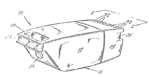
Now referring to the Figures, canister type
vacuum cleaner 10, constructed in accordance with
teachings of the instant invention, includes casing 11,
have a tank section 12 at the front and motor housing
14 at the rear. As seen in Figures 3 and 4, disposed
within casing 11 are motor 25 and main molded plastic
elements 75 (secondary filter support), 30 (fan
housing), 55 (motor mounting plate) and 60 (baffle).
Inlet 15 to tank 12 is through passage 16
defined by cylindrical neck 17 that extends rearward
from front surface 18 of tank 12. Handle 19 molded
integrally with tank 12 is disposed at the front
thereof in a position that permits one end of a tool
hose (not shown) to be removably connected to tank 12
over its inlet 15. Dirt drawn into tank 12 through
inlet 15 is trapped within porous paper bag 20 that
acts as a primary filter in protecting air-cooled motor
25 against dust and dirt. Stiffener 21 at the open end
of bag 20 is provided with annular collar 22 that
surrounds neck 17 and is wedged thereagainst two
removably secure bag 20 to neck 17.
Depression 23 in the front surface of handle
19 defines a space for the storage of line cord 24 as
it is wound around casing 11. Other storage spaces for
line cord 24 are provided by depressions 26, 26 along
opposite edges of motor housing 14 at the rear thereof.
Tank 12 and housing 14 abut the front and rear surfaces
respectively of narrow, generally rectangular band
formation 27 formed integrally with fan housing 30 at
~.~
~638634
the rear thereof. As seen in Figure 3 fan housing 30
is also provided with shallow upward projection 28
positioned forward of band formation 27. Projection 28
is received by a complementary depression in the
internal surface of tank 12 in the vicinity of the rear
end thereof so that the top of the tank is held in
position by projection 28. The bottom of tank 12 at
the transverse center thereof mounts bucklet 35 that is
a one piece rnolded plastic member, preferably
constructed of nylon or acetate and including latch
formation 34 at one end thereof, hook formation 33 at
the other end thereof and skid 32 at the mid-region
thereof. When the supporting surface 31 (Figure 3-4)
for vacuum 10 is horizontal, skid 32 engages surface 31
as do wheels 36, 36 that are rotatably mounted to motor
housing 14 at the rear thereof.
Latch 34 is received by a cooperating
depression in motor housing 14 to firmly secure the
lower portions of tank 12 and motor housing 14
together. This connection is releasable in that latch
34 may be removed from its cooperating depression in
motor housing 14 by applying force at finger-engagable
extension 37, formed integrally with buckle 35, at the
rear thereof to bend buckle 35 as re~uired to release
latch 34.
Motor 25 is disposed within housing 14 and
includes stater 41 and rotor 42 having sha~t 43
extending therethrough. The windings of rotor 42 are
electrically connected to line cord 24 in a
conventional manner including switch 44 and leads 46,
47, 98. Grommet 98 (Figure 3) surrounds line cord 24
where it enters housing 14 through rear wall 99
, ,.
~2~3~
-- 6 --
thereof. Shaft 43 is rotatably supported by bearings
(not shown) disposed at opposite ends thereof, with one
of these bearings being mounted to U-shaped bracket 48
and the other being mounted to molded plastic end bell
50.
Pancake type centrifugal fan impeller 51 is
secured to the rear end o motor shaft 43 so as to be
rotatable therewith. Impeller 51 is disposed within
shallow chamber 52 that is defined b~ fan housing 30
and is substantially closed at the rear thereo by
motor mounting plate 55 (Figure 6). The latter
includes circular aperture 56 at the center thereof to
received annular extension 56 at the from of end bell
50. Mounting plate 55 also includes apertures 57, 57
disposed on opposite sides of central aperture 56.
Each aperture 57 receives a bushing 58 that surrounds a
stud 59 formed integrally with end bell 50. Mechanical
securement of motor 25 to its mounting plate 55 is
completed by screws 61, 61 that are threadably received
in longitudinal passages (not shown) that extend to the
fronts of studs 59, 59.
Fan housing 30 (Figure 7), motor mounting
plate 55 and baffle 60 at the rear of motor 25 are
mechanically secured within motor housing 14 by a
common astening means provided by four screws 121 each
of which is threadably received in an individual
passage 62 that extends to the forward end o one of
four posts 63 that are disposed within motor housing 14
and extend forward from rear wall 99 thereof, being
molded integrally therewith. Each post 63 extends into
one of four hollow studs 64 through the open rear end
thereof. Stud 64 includes a shallow depression at its
~1.263~3~4
front end which receives the rear end of a post 66 that
extends rearward from motor mounting plate 55. Post 66
and stud 64 are provided with clearance apertures
through which screw 121 extends. ~ead 67 of screw 121
bears against the forward facing surface of fan housing
30 that is at the rear of longitudinal depression 68
and stud 81.
Fan housing 30 also includes annular wall 71
that is concentric with the outer edge of impeller 51
and in close proximity thereto. Central aperture 72 in
transverse wall 74 of housing 30 is concentric with
wall 71 and provides the inlet through which air
reaches impeller 51. Disposed outboard of wall 71 are
four apertures 73 that extend through the fan housing
wall 74. Each aperture 73 receives one of four
rearwardly projecting cars 176 of support 75 (Figure 8)
for secondary filter 76 the latter being a sheet of
filter material that is removably held by six inwardly
projecting tabs 77 of support 75. The rear ends of
tabs 74 are upset, as by applying heat thereto, thereby
mechanically securing support 75 to the front of fan
housing 30. Main platelike section 78 of support 75 is
provided with an array of slots 120 to minimize
interference with airflow to impeller 51 and to utilize
a maximum amount of filter area. Apertures 79 at the
corners of main section 78 are aligned with depressions
68 to permit access to heads 67 of screws 121 when
filter 76 is removed. Screw heads 67 are not visible
to the user when filter 76 is in operative position
during normal use.
Ba~fle 60 (Figure 5) includes main wall 82
that extends across the interior of motor housing 14
f
~ 2 ~ 8~
and at its central region is provided with cup 83
wherein the rear half of motor 25 is disposed. A
plurality of apertures 84 in cup 83 near the rear
thereof provide air flow openings. Baffle member 60
also defines chamber 122 wherein sw;tch 44 is disposed
with its operating member 86 extending through housing
aperture 87 and being engaged by manually operable
slide 88 that is accessible outside of motor housing 14
for selectively operating motor 25 on and off.
Baffle 60 is snap fitted on bracket 48
through the cooperation of bracket projections 48a (one
seen in Figure 4) and baffle apertures 60a (one seen in
Figure 4) to constitute an independent subassembly in
which aperture radial projection 50a of end bell 50
provides a finger-proof front for chamber 122. End
ball 50 and baffle 60 are constructed of flame
retardant material so that even if other housing
elements are broken or destroyed the uninsulated
electrical connections at switch ~4 will be surrounded
by flame retardant material.
As seen best in Figures 3 and 4, rotation of
fan impeller 51 by motor 25 moves air through casing 11
along indicated by the broken lines having arrowheads
thereon. That is, rotating impeller 51 draws air into
tank 12 through inlet 15 and passage 16. This is the
main or working air that creates a suction force at a
pick-up tool (not shown) disposed at one end of a
flexible hose (not shown) whose other end is removably
connected to vacuum cleaner 10 at inlet 15, in a manner
well known to the art. Air and dirt particles that
enter tank 18 enter bag 20 that constitutes a primary
filter which traps the dirt. Air flows rearward
~,
~ ~ ~3 8~
through bag 20 and then flows through secondary filter
76, typically a flexible sheet of open cell foam
material, and slots 120 into impeller chamber 96
through central aperture 72 thereof. Air flow is then
radially outward, being deflected rearwardly again by
wall 71 and flowing through apertures 95 in motor
mounting plate 55. As seen best in Figure 6, each of
the apertures 95 is of relatively small diameter and
the plurality of apertures 95 is arranged in a narrow
annular array or band consisting of three rows. This
arrangement of many small apertures 95, typically 270
in number, suppresses noise without creating excessive
back pressure.
Air flow to the rear of motor mounting plate
55 is alongside and through motor 25 to cool the
latter. Some of the flow is through apertures 94 in
end bell 50. Because o~ the configuration of baffle
60, air flow is for the most part directed into cup 83
and circular aperture 83, and exits motor housing 14 at
the rear thereof through slotted apertures 92. Foam
noise suppressor 91 is disposed in the air path, being
inside of motor housing 19 is disposed in the air path,
being inside of motor housing 19 in front of slots 92.
The amount of air forced through motor 25 for cool;ng
thereo~ may be adjusted by providing apertures (not
shown) in transverse wall 82 of baffle 60.
Tank 12 may be released from motor housing 14
by merely disengaging latch 34 from housing 14 and
thereafter pivoting tank 12 counterclockwise in an
upward direction with respect to Eigure 3 about band
27. Bag 20 is then accessible for removal from tank
12, Bag 20 may be either a reusable or replaceable
type.
.~ ,..
.v