Note: Descriptions are shown in the official language in which they were submitted.
~ 3~ Case 6561
ANODE CLAMP
Background of the Invention
This invention pertains to anode clamps used in
an aluminum reduction cell, and particularly to such clamps
useful during baka-out of the cathode of the cell.
Aluminum is commonly produced by the electrolytic
5 reduction of aluminum oxide to aluminum metal in an elec-
trolytic cell comprising a carbonaceous cathode which forms
a dish for holding the molten aluminum produced, toge~her
with an overlying layer of electrolyte or bath in which the
aluminum oxide to be reduced is dissolved. An electric
10 current is introduced into the cell by means of anodes sus-
pended in and contacting the electrolytic bath. These
anodes are mechanically and electrically connected by means
of ver~ical anode rods embedded in the anodes and attached
to anode bus bars suspended over the reduction cell. Uni-
15 directional electric current is introduced to the cellthrough the anode bus, anode rods, and anodes, passing
through the electrolytic bath, thereby reducing the aluminum
oxide to aluminum metal, and leaves the cell by passing
through the pad of molten aluminum and the underlying
20 cathode, from which it is removed by collector bars and
thence carried to the anode bus of the adjacent cell.
Because the anodes are consumed in the electro-
lytic reduction process, and because molten aluminum builds
up within the cell and i5 removed ~rom time to time, it is
25 necessary to vertically adjust the position of the anodes
so as to maintain a roughly constant distance between the
anode face and the layer of molten aluminum. Accordingly,
the clamps by which the anode rods are attached to the anode
bus must permit vertical adjustment from time to time. Such
30 anode clamps are well known and exemplary showings are given
in U.S. 3,575,840, U.S. 3,888,757, and U.S. 4~025,414. While
such prior art anode clamps are adequate for use during
operation o the cell r they are far from satisfactory for
,,~' q~.,
: ,~
3''3~3
--2--
use during the so-called cathode "bake-out" period.
After a reduction cell has been newly constructed
or rebuilt after a campaign of use, it is necessary, prior
to operation of the cell, to preheat or bake the cathode,
that is to say r the carbonaceous material at the bottom of
the cell which forms a container for the molten aluminum
and overlying molten electrolyte. While there are various
methods of conducting such bake-out, one common method is
to do it by passing electric cuxrent through the cell.
In this method, a bed of sized carbon resistor
material i5 evenly spread over the carbon blocks making up
the cathode, and the anodes with attached anode rods are
lowered onto the bed. Partial or full line amperage is
then fPd through the cell and the resistance heat generated
bakes the cathode ramming paste placed between and around
the cathode blocks and heats up the cathode body prior to
introduction of the electrolytic bath.
Because of thermal expansion of both the anode
and cathode blocks, it is necessary to readjust the anode
rod clamps frequently during this bake-out process, for
example every hour or so. Accordingly, this method of
bake-out is highly labor intensive, and consequently expen-
sive, when it is realized that a normal bake-out can take
from 20 to 36 hours or more.
Frequently, there is not enough manpower to per-
~orm the required anode clamp adjustments as often as
desirable. Failure to adjust the anode clamps leads to
uneven anode current distribution, with consequent localized
hot spots in the cathode. These can cause cracks within
the cathode blocks and the anode blocks and assemblies can
also be damaged. Also, some areas of the cathode will not
heat up adequately. All these problems can cause subsequent
operational difficulties and reduce the overall life of the
cell.
At leas~ two methods have been proposed to over-
come these problems of bake~out. One is to leave the anode
~3
--3--
clamps loose. However, since typical anode clamps are not
designed to allow slippage between the anode rods and the
anode bus, loosening them enough to allow such slippage
leads to nonuniform current flow. Also, such looseness
tends to lead to electric arcing between the anode rod and
and anode bus, causing pitting of the surfaces of both.
Another solution is to use temporary flexible
straps to connect the anode rods and anode bus during the
bake~out period, while leaving the clamps loose. However,
such straps are heavy and difficult to connect; in some
instances, it is necessary to use a crane to place and
remove them. Also, such flexible strap equipment is
expensive and easily damaged if not handled properly.
Finally, such straps can be difficuIt to remove in the
extremely hot environment over an aluminum reduction cell.
The present invention is directed to a simplified
and more satisfactory solution to the problem of an anode
clamp for use during bake-out of an aluminum reduction cell.
Summary of_the Invention
It has now been found, according to this invention,
that a satisfactory anode clamp for use during bake-out is
one comprising ~1) a yoke adapted to be at-tached to the
anode bus of an aluminum reduction cell, (2) contact means
carried by the yoke and adapted to engage an anode rod in
the aluminum cell in such a manner as to permit relative
motion along the longitudinal axis of the anode rod between
the contact means and the anode rod, and (3) resilient
means carried by the yoke to urge the contact means into
contact with the anode rod.
Brief Description of_Drawings
; Figure l is a perspective view of a clamp accord- ing to this invention;
Figure 2 is a sectional view along the line 2--2
of Figure 3, with certain parts omitted for purposes of
clarity;
.. . .
3L~3
~4--
Figure 3 is a plan viewl partially in section~
of an anode clamp according to the present invention in
place; and
Figure 4 is a front elevation view o-f the clamp.
Detailed Description
One embodiment of the invention, the scope of
which is defined in the claims, is shown in the drawings
and hereafter described.
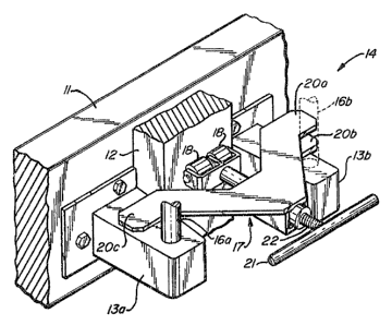
In the drawings, 11 indicates the anode bus and
12 the anode rod to be clamped thereto. Brackets 13a and
13b are bolted to anode bus 11 and carry the removable
anode clamp, generally indicated by 14, which is reta:ined
in place by bearing against studs 16a and 16b, on brackets
13. Brackets 13 and studs 16 are part of the regular,
permanent anode clamp, the details of which are not shown
for purposes of clarity in illustrating the removable anode
clamp of the present invention. It will be understood by
those skilled in the art that studs 16 are rotated to
engage arms ~not shown) that are part of the permanent
clamp ~or anode rod 12. It will also be understood that
details of the structure of the clamp of the present inven-
tion may be modified so that it will fit mechanically on
other forms of regular or permanent anode clamps or on ~he
brackets carrying such ~lamps.
The clamp of this invention comprises a generally
U-shaped yoke 17, the ends 20b and 20c of which rest on
bracke-ts 13, and the central portion of which carries
rollers 18 which bear against anode rod 12.
(In the specific e~bodiment shown in the drawings,
bracket 13b is lower than bracket 13a. Accordingly, one
arm of yoke 17 is off-set from the other. To prevent twist-
ing of the clamp when i~ is engaged, one arm of yoke 17 is
made of two pieces alower piece 20b which rests on bracket
13b and an upper piece 20a located in the same plane as the
opposite arm 20c o yoke 17. It will be understood that
this arrang~ment is peculiar to use of the clamp of the
9f~8
--5--
present invention with the particular configuration shown,
and is not an essential feature of the invention.~
As shown more clearly in Figure 2, rollers 18 are
urged against anode rod 12 by spring 19 within a housing
carried on yoke 17. In addition, handle 21 turns threaded
rod 22 so as to increase or decrease l~e force exerted by
spring 19 on rollers 18. While the spring us~d may be any
suitable type of spring, the type of spring known as a
spring washer or Bellville spring has been used success-
fully, and is illustrated schematically in Figure 2.
The clamp of the present invention may be made ofany suitable material, usually nonmagnetic, for example
stainless s~eel. Xowever, parts, for example ~he rollers~
may be made of other suitable materials such as high tem-
perature plastic.
It will be appreciated that the clamp of thepresent invention is set in position during the bake-out
operation, after which it can be removed and the conven-
tional clamp, as mentioned above, engaged while the cell
is being operated to produce aluminum.
It will also be understood that either spring 19
alone or screw 22 alone can be used to exert pressure on
roller 18, although a combination of the two can be used.
The advantages of the clamp of the present inven-
tion over prior art clamps is that the anode rod can movevertically in response to expansion of the anode and/or
cathode during bake-out, while at the same time intimate
contact is maintained between the anode rod and the anode
bus. Also, the clamps of the present invention are simply
and easily installed and removed, particularly because of
their relatively light weight compared with, for example,
flexible straps. Finally, the clamps of the present inven-
tion are relatively inexpensive to manufacture, easy to
maintain, and durable.
It will be understood that the spring and roller
pieces shown can be replaced by equivalent structures. For
....
~3~3
--6--
example, instead of a spring, one could use an hydraulic
or pneumatic force exerting cell. Similarly, instead of
the rollers, on~ could use a curved leaf spring to main-
tain the anode rod in contact with the anode bus while at
the same time permitting relative vertical movement between
the two.
.. ,
. . ~ .