Language selection

Search

Patent 1263968 Summary

Third-party information liability

Some of the information on this Web page has been provided by external sources. The Government of Canada is not responsible for the accuracy, reliability or currency of the information supplied by external sources. Users wishing to rely upon this information should consult directly with the source of the information. Content provided by external sources is not subject to official languages, privacy and accessibility requirements.

Claims and Abstract availability

Any discrepancies in the text and image of the Claims and Abstract are due to differing posting times. Text of the Claims and Abstract are posted:

  • At the time the application is open to public inspection;
  • At the time of issue of the patent (grant).
(12) Patent: (11) CA 1263968
(21) Application Number: 1263968
(54) English Title: SEAL FOR RELATIVELY ROTATABLE PARTS
(54) French Title: JOINT POUR PIECES DONT L'UNE TOURNE DANS L'AUTRE
Status: Term Expired - Post Grant
Bibliographic Data
(51) International Patent Classification (IPC):
  • F16J 15/3204 (2016.01)
  • F16J 15/34 (2006.01)
(72) Inventors :
  • LEWIS, FREDERICK S. (United States of America)
  • MUNSON, ROBERT W. (United States of America)
(73) Owners :
  • GROUPE LAPERRIERE & VERREAULT INC.
(71) Applicants :
  • GROUPE LAPERRIERE & VERREAULT INC. (Canada)
(74) Agent: NORTON ROSE FULBRIGHT CANADA LLP/S.E.N.C.R.L., S.R.L.
(74) Associate agent:
(45) Issued: 1989-12-19
(22) Filed Date: 1986-04-14
Availability of licence: N/A
Dedicated to the Public: N/A
(25) Language of filing: English

Patent Cooperation Treaty (PCT): No

(30) Application Priority Data:
Application No. Country/Territory Date
783,176 (United States of America) 1985-10-02

Abstracts

English Abstract


SEAL FOR RELATIVELY ROTATABLE PARTS
The external seal is mounted on a housing about a rotary
shaft projecting through an opening in the housing. The seal
is a resilient, flexible member having a generally tubular body
portion with an annular lip extending radially outwardly from
one end of the body portion and a flange extending radially
outwardly from the other end of the body portion. The lip
extends into a sealing chamber formed by the outside of the
housing and a replaceable sealing member which has an inside
surface spaced from and parallel to the outside of the housing.
The tubular portion of the seal extends through an
annulus formed by the shaft and the replaceable member.
The outwardly extending flange is used to prevent the
clamp holding the seal to the shaft from falling out.


Claims

Note: Claims are shown in the official language in which they were submitted.

The embodiments of the invention in which an
exclusive property or privilege is claimed
are defined as follows:
1. In combination with a rotary shaft projecting
through an opening in a housing having a housing wall extending
transversely of said shaft: a replaceable member positioned
outside of the housing and mounted on said housing about the
shaft, said replaceable member having a bore of larger diameter
than the diameter of the shaft to provide a replaceable
member-shaft annulus, said replaceable member having an inside
surface parallel to and spaced from said housing wall to form
a sealing chamber; a seal of resilient flexible material having
a generally tubular body portion extending through the
replaceable member-shaft annulus, an integral annular thin
flexible lip connected by a hinge at one axial end of the body
portion, said annular lip being located within the sealing
chamber and extending outwardly radially and axially toward the
tubular body portion, the radially outer portion of the inner
surface of said lip being in sealing contact with said inside
surface of the replaceable member, and a clamp retaining flange
extending radially outwardly from the other axial end of the
body portion; and a cylindrical clamp mounted about the
generally tubular body portion of the seal to secure the seal
to the rotary shaft.
2. The combination of claim 1 wherein: said flexible
lip extends radially from the bore of the seal at least three
times the radial thickness of the tubular body of the seal.
- 6 -

Description

Note: Descriptions are shown in the official language in which they were submitted.


~ ~3 ~
This invention relates to seals adapted to provide a
seal between a shaft and a housing having a surface extending
transversely to the axis of rotation of l:he shaft. More
particularly, this invention relates to radial lip seals.
In a radial lip seal the lip on the seal extends
generally perpendicular to the axis of the rotary shaft being
sealed. The radial lip seal is held on and rotates with the
shaft. It usually seals against a ring or other member
perpendicular to the shaft.
With conventional radial lip seals there are two major
disadvantages. Firstly, there is no positive clamping action.
The seal is stretched around the sha~t and relies on the
resilience o~ the seal material to maintain a clamping action.
Secondly, when sealing a~ain5t internal 1~id or press~re, the
major portion of the seal is exposed to the sealed material.
In severe applications, the seal will suffer accelerated
chemical attack and this will impair its clamping resilience.
If a metal clamp is used with the seal, it would also be
exposed to the material being sealed and accessibility would be
difficult. Also, seal water cannot be effectively applied to
conventional seals.
The seal of this invention has two main advantages
over the conventional radial lip seal. Firstly, the seal
will have and externally accessible metal clamp which will
provide a positive mechanical hold and will not rely on
the material resilience. Secondly, only the upper surface
of the seal is exposed to the material sealed internally
-- 1 --
.. . .
;,
:

~ ~ ~3~3~
in the ho~sing. Most o the seal is not exposed to the
sealed material within the housing.
Briefly described an external replaceable member, a
resilient flexiable seal, and a cylindrical clamp for securing
the seal to the rotary shaft is used in combination with the
rotary shaft. The replaceable member is positioned externally
of the housing and mounted on the housing about the shaft. The
replaceable member has a bore of larger diameter than the
diameter of the shaft to provide a replaceable member-shaft
annulus. The replaceable member has an inside surface which is
parallel to and spaced from the housing outside wall to ~orm a
sealing chamber.- The resilient flexible seal has a generally
tubular body portion extending through the replaceable
member-shaft annulus. The seal also has an integral annular
thin flexible lip connected by a hinge at one axial end o the
body portion. rrhe lip is located witbin the sealing chamber
and extends outwardly radially and axially toward the body
portion. The radially ou~er portion of the inner sur~ace of
the lip is in sealing contact with the inside surace of the
reelaceable member. A clamp retaining flange extends radially
outwardly from the other axial end of the body portion. A
cylindrical clamp is mounted about the generally tubular body
portion of the seal to ecure the seal to the rotary shaft.
The invention, as well as its many advantages, may be
further ~nderstood by reference to the following detailed
description and drawing in which:
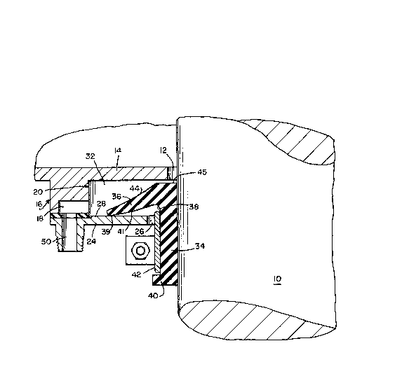
Fig. 1 is an elevational view, partly in section, show~
ing one embodiment of the seal made in accordance with the
present invention; and
. .~

i3!3t:i8
Fig. 2 is a bottom view on a smaller scale, of the hous-
ing wall and annular protrusion of Fig. l.
In the various Figures, like parts are referred to by
like numbers.
Re~erring to the drawing, and particularly to Fig. l, a
rotary shaft 10 extends through a bore ]2 in the housing wall
14, which exte~ds transversely from the rotary shaft 10.
Housing wall 14 has an annular protrusion 16 extending
outwardly from the housing. A small recess 18 ~see Fig. 2) ex-
tends from the l-ower end of the protrusion part way into the
protrusion. A counterbore 20 extends ~rom the lower end of the
protrusion to housing wall 14.
A eeplaceable external sealing ring 24 is mounted about
the rotary ~haft 10 and is connected to the protrusion 16 of
the housing wall 14. The bore 26 in the center of the sealing
ring has a larger diameter than the diameter of the shaft thus
providing a sealing ring shaft annulus.
The inside surface 28 o~ the sealing ring is spaced from
and parallel to the housing wall 14 to form a sealing chamber
32.
A seal made of a resilient 1exible material such as
natural rubber, neoprene, viton, or Nitrile seals the material
within the housing. The seal consists of a generally tubular
body portion 3~ extending through the sealing ring-shaft
ann~lus, an integral annular thin flexible lip 36 connected by
a hinge 38 at one axial end of the body portion 3~ and a clamp
- 3 -
:: ,
, .

~ 3'~'3~8
retaining flange 40 extending radially outwardly from the other
axial end of the body portion 34.
The annular lip 36 is located entirely within the
sealing chamber 32 and extends outwardly radially and axially
5 toward the body portion 34. The radially outer portion 39 of
the inside surface 41 of the lip 36 is in sliding sealing
contact with the inside surface 28 of the sealing ring. Note
that the lip 36 is quite long compared to the length of the
tubular body 34, The flexible lip extends radially from the
bore of the seal at least three times the radial thickness of
the tubular body 34. The radial extent of the lip 36 from the
bore of the seal is more than one-half the total axial length
of the seal.
A cylindrical clamp 42 is mounted about the geneeally
lS tubular body 34 of the seal to secure the seal to the rotary
shaft 10. Flange ~0 o~ the seal retains the clamp 42 in
position,
The metal clamp 42 will not slide off of the body of the
seal because of the flange 40 on the seal.
In operation, the seal is mounted on and rotates with
the shaft 10. The sealing lip keeps contact with the
stationary replaceable sealing ring. Note that the entire
structure of the seal except for the upper surface 44 o~ the
sealing lip and the upper surface 45 of the tubular body 34 is
external to the material to be sealed and therefore is not ex-
posed to the material being sealed. Even deterioration of that
external portion of the seal which is exposed to the fluid
being sealed may be minimized by diluting the material being
-- 4 --

~2~39~
sealed with fresh sealing water which may be fed through fluid
conduit 50 formed through the sealing ring 24, and through
recess 18 into sealing chamber 32.
: :
:~ :
, :
.~

Representative Drawing
A single figure which represents the drawing illustrating the invention.
Administrative Status

2024-08-01:As part of the Next Generation Patents (NGP) transition, the Canadian Patents Database (CPD) now contains a more detailed Event History, which replicates the Event Log of our new back-office solution.

Please note that "Inactive:" events refers to events no longer in use in our new back-office solution.

For a clearer understanding of the status of the application/patent presented on this page, the site Disclaimer , as well as the definitions for Patent , Event History , Maintenance Fee  and Payment History  should be consulted.

Event History

Description Date
Inactive: IPC deactivated 2020-02-15
Inactive: First IPC assigned 2019-01-09
Inactive: IPC assigned 2019-01-09
Inactive: IPC expired 2016-01-01
Inactive: Expired (old Act Patent) latest possible expiry date 2006-12-19
Inactive: IPC from MCD 2006-03-11
Inactive: Late MF processed 2003-12-03
Letter Sent 2003-10-10
Grant by Issuance 1989-12-19

Abandonment History

There is no abandonment history.

Owners on Record

Note: Records showing the ownership history in alphabetical order.

Current Owners on Record
GROUPE LAPERRIERE & VERREAULT INC.
Past Owners on Record
FREDERICK S. LEWIS
ROBERT W. MUNSON
Past Owners that do not appear in the "Owners on Record" listing will appear in other documentation within the application.
Documents

To view selected files, please enter reCAPTCHA code :


To view images, click a link in the Document Description column. To download the documents, select one or more checkboxes in the first column and then click the "Download Selected in PDF format (Zip Archive)" or the "Download Selected as Single PDF" button.

List of published and non-published patent-specific documents on the CPD .

If you have any difficulty accessing content, you can call the Client Service Centre at 1-866-997-1936 or send them an e-mail at CIPO Client Service Centre.


Document
Description 
Date
(yyyy-mm-dd) 
Number of pages   Size of Image (KB) 
Abstract 1993-09-15 1 23
Cover Page 1993-09-15 1 17
Claims 1993-09-15 1 38
Drawings 1993-09-15 1 29
Descriptions 1993-09-15 5 152
Representative drawing 2001-06-29 1 19
Fees 1993-11-12 1 22
Fees 1996-12-04 1 33
Fees 1995-11-10 1 36
Fees 1994-11-14 1 36
Fees 1992-11-18 1 17
Fees 1991-11-08 1 94