Sélection de la langue

Search

Sommaire du brevet 1263968 

Énoncé de désistement de responsabilité concernant l'information provenant de tiers

Une partie des informations de ce site Web a été fournie par des sources externes. Le gouvernement du Canada n'assume aucune responsabilité concernant la précision, l'actualité ou la fiabilité des informations fournies par les sources externes. Les utilisateurs qui désirent employer cette information devraient consulter directement la source des informations. Le contenu fourni par les sources externes n'est pas assujetti aux exigences sur les langues officielles, la protection des renseignements personnels et l'accessibilité.

Disponibilité de l'Abrégé et des Revendications

L'apparition de différences dans le texte et l'image des Revendications et de l'Abrégé dépend du moment auquel le document est publié. Les textes des Revendications et de l'Abrégé sont affichés :

  • lorsque la demande peut être examinée par le public;
  • lorsque le brevet est émis (délivrance).
(12) Brevet: (11) CA 1263968
(21) Numéro de la demande: 1263968
(54) Titre français: JOINT POUR PIECES DONT L'UNE TOURNE DANS L'AUTRE
(54) Titre anglais: SEAL FOR RELATIVELY ROTATABLE PARTS
Statut: Durée expirée - après l'octroi
Données bibliographiques
(51) Classification internationale des brevets (CIB):
  • F16J 15/3204 (2016.01)
  • F16J 15/34 (2006.01)
(72) Inventeurs :
  • LEWIS, FREDERICK S. (Etats-Unis d'Amérique)
  • MUNSON, ROBERT W. (Etats-Unis d'Amérique)
(73) Titulaires :
  • GROUPE LAPERRIERE & VERREAULT INC.
(71) Demandeurs :
  • GROUPE LAPERRIERE & VERREAULT INC. (Canada)
(74) Agent: NORTON ROSE FULBRIGHT CANADA LLP/S.E.N.C.R.L., S.R.L.
(74) Co-agent:
(45) Délivré: 1989-12-19
(22) Date de dépôt: 1986-04-14
Licence disponible: S.O.
Cédé au domaine public: S.O.
(25) Langue des documents déposés: Anglais

Traité de coopération en matière de brevets (PCT): Non

(30) Données de priorité de la demande:
Numéro de la demande Pays / territoire Date
783,176 (Etats-Unis d'Amérique) 1985-10-02

Abrégés

Abrégé anglais


SEAL FOR RELATIVELY ROTATABLE PARTS
The external seal is mounted on a housing about a rotary
shaft projecting through an opening in the housing. The seal
is a resilient, flexible member having a generally tubular body
portion with an annular lip extending radially outwardly from
one end of the body portion and a flange extending radially
outwardly from the other end of the body portion. The lip
extends into a sealing chamber formed by the outside of the
housing and a replaceable sealing member which has an inside
surface spaced from and parallel to the outside of the housing.
The tubular portion of the seal extends through an
annulus formed by the shaft and the replaceable member.
The outwardly extending flange is used to prevent the
clamp holding the seal to the shaft from falling out.

Revendications

Note : Les revendications sont présentées dans la langue officielle dans laquelle elles ont été soumises.


The embodiments of the invention in which an
exclusive property or privilege is claimed
are defined as follows:
1. In combination with a rotary shaft projecting
through an opening in a housing having a housing wall extending
transversely of said shaft: a replaceable member positioned
outside of the housing and mounted on said housing about the
shaft, said replaceable member having a bore of larger diameter
than the diameter of the shaft to provide a replaceable
member-shaft annulus, said replaceable member having an inside
surface parallel to and spaced from said housing wall to form
a sealing chamber; a seal of resilient flexible material having
a generally tubular body portion extending through the
replaceable member-shaft annulus, an integral annular thin
flexible lip connected by a hinge at one axial end of the body
portion, said annular lip being located within the sealing
chamber and extending outwardly radially and axially toward the
tubular body portion, the radially outer portion of the inner
surface of said lip being in sealing contact with said inside
surface of the replaceable member, and a clamp retaining flange
extending radially outwardly from the other axial end of the
body portion; and a cylindrical clamp mounted about the
generally tubular body portion of the seal to secure the seal
to the rotary shaft.
2. The combination of claim 1 wherein: said flexible
lip extends radially from the bore of the seal at least three
times the radial thickness of the tubular body of the seal.
- 6 -

Description

Note : Les descriptions sont présentées dans la langue officielle dans laquelle elles ont été soumises.

~ ~3 ~
This invention relates to seals adapted to provide a
seal between a shaft and a housing having a surface extending
transversely to the axis of rotation of l:he shaft. More
particularly, this invention relates to radial lip seals.
In a radial lip seal the lip on the seal extends
generally perpendicular to the axis of the rotary shaft being
sealed. The radial lip seal is held on and rotates with the
shaft. It usually seals against a ring or other member
perpendicular to the shaft.
With conventional radial lip seals there are two major
disadvantages. Firstly, there is no positive clamping action.
The seal is stretched around the sha~t and relies on the
resilience o~ the seal material to maintain a clamping action.
Secondly, when sealing a~ain5t internal 1~id or press~re, the
major portion of the seal is exposed to the sealed material.
In severe applications, the seal will suffer accelerated
chemical attack and this will impair its clamping resilience.
If a metal clamp is used with the seal, it would also be
exposed to the material being sealed and accessibility would be
difficult. Also, seal water cannot be effectively applied to
conventional seals.
The seal of this invention has two main advantages
over the conventional radial lip seal. Firstly, the seal
will have and externally accessible metal clamp which will
provide a positive mechanical hold and will not rely on
the material resilience. Secondly, only the upper surface
of the seal is exposed to the material sealed internally
-- 1 --
.. . .
;,
:

~ ~ ~3~3~
in the ho~sing. Most o the seal is not exposed to the
sealed material within the housing.
Briefly described an external replaceable member, a
resilient flexiable seal, and a cylindrical clamp for securing
the seal to the rotary shaft is used in combination with the
rotary shaft. The replaceable member is positioned externally
of the housing and mounted on the housing about the shaft. The
replaceable member has a bore of larger diameter than the
diameter of the shaft to provide a replaceable member-shaft
annulus. The replaceable member has an inside surface which is
parallel to and spaced from the housing outside wall to ~orm a
sealing chamber.- The resilient flexible seal has a generally
tubular body portion extending through the replaceable
member-shaft annulus. The seal also has an integral annular
thin flexible lip connected by a hinge at one axial end o the
body portion. rrhe lip is located witbin the sealing chamber
and extends outwardly radially and axially toward the body
portion. The radially ou~er portion of the inner sur~ace of
the lip is in sealing contact with the inside surace of the
reelaceable member. A clamp retaining flange extends radially
outwardly from the other axial end of the body portion. A
cylindrical clamp is mounted about the generally tubular body
portion of the seal to ecure the seal to the rotary shaft.
The invention, as well as its many advantages, may be
further ~nderstood by reference to the following detailed
description and drawing in which:
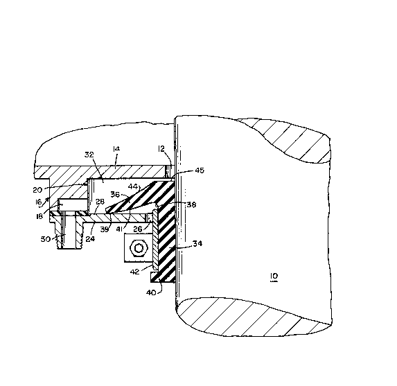
Fig. 1 is an elevational view, partly in section, show~
ing one embodiment of the seal made in accordance with the
present invention; and
. .~

i3!3t:i8
Fig. 2 is a bottom view on a smaller scale, of the hous-
ing wall and annular protrusion of Fig. l.
In the various Figures, like parts are referred to by
like numbers.
Re~erring to the drawing, and particularly to Fig. l, a
rotary shaft 10 extends through a bore ]2 in the housing wall
14, which exte~ds transversely from the rotary shaft 10.
Housing wall 14 has an annular protrusion 16 extending
outwardly from the housing. A small recess 18 ~see Fig. 2) ex-
tends from the l-ower end of the protrusion part way into the
protrusion. A counterbore 20 extends ~rom the lower end of the
protrusion to housing wall 14.
A eeplaceable external sealing ring 24 is mounted about
the rotary ~haft 10 and is connected to the protrusion 16 of
the housing wall 14. The bore 26 in the center of the sealing
ring has a larger diameter than the diameter of the shaft thus
providing a sealing ring shaft annulus.
The inside surface 28 o~ the sealing ring is spaced from
and parallel to the housing wall 14 to form a sealing chamber
32.
A seal made of a resilient 1exible material such as
natural rubber, neoprene, viton, or Nitrile seals the material
within the housing. The seal consists of a generally tubular
body portion 3~ extending through the sealing ring-shaft
ann~lus, an integral annular thin flexible lip 36 connected by
a hinge 38 at one axial end of the body portion 3~ and a clamp
- 3 -
:: ,
, .

~ 3'~'3~8
retaining flange 40 extending radially outwardly from the other
axial end of the body portion 34.
The annular lip 36 is located entirely within the
sealing chamber 32 and extends outwardly radially and axially
5 toward the body portion 34. The radially outer portion 39 of
the inside surface 41 of the lip 36 is in sliding sealing
contact with the inside surface 28 of the sealing ring. Note
that the lip 36 is quite long compared to the length of the
tubular body 34, The flexible lip extends radially from the
bore of the seal at least three times the radial thickness of
the tubular body 34. The radial extent of the lip 36 from the
bore of the seal is more than one-half the total axial length
of the seal.
A cylindrical clamp 42 is mounted about the geneeally
lS tubular body 34 of the seal to secure the seal to the rotary
shaft 10. Flange ~0 o~ the seal retains the clamp 42 in
position,
The metal clamp 42 will not slide off of the body of the
seal because of the flange 40 on the seal.
In operation, the seal is mounted on and rotates with
the shaft 10. The sealing lip keeps contact with the
stationary replaceable sealing ring. Note that the entire
structure of the seal except for the upper surface 44 o~ the
sealing lip and the upper surface 45 of the tubular body 34 is
external to the material to be sealed and therefore is not ex-
posed to the material being sealed. Even deterioration of that
external portion of the seal which is exposed to the fluid
being sealed may be minimized by diluting the material being
-- 4 --

~2~39~
sealed with fresh sealing water which may be fed through fluid
conduit 50 formed through the sealing ring 24, and through
recess 18 into sealing chamber 32.
: :
:~ :
, :
.~

Dessin représentatif
Une figure unique qui représente un dessin illustrant l'invention.
États administratifs

2024-08-01 : Dans le cadre de la transition vers les Brevets de nouvelle génération (BNG), la base de données sur les brevets canadiens (BDBC) contient désormais un Historique d'événement plus détaillé, qui reproduit le Journal des événements de notre nouvelle solution interne.

Veuillez noter que les événements débutant par « Inactive : » se réfèrent à des événements qui ne sont plus utilisés dans notre nouvelle solution interne.

Pour une meilleure compréhension de l'état de la demande ou brevet qui figure sur cette page, la rubrique Mise en garde , et les descriptions de Brevet , Historique d'événement , Taxes périodiques et Historique des paiements devraient être consultées.

Historique d'événement

Description Date
Inactive : CIB désactivée 2020-02-15
Inactive : CIB en 1re position 2019-01-09
Inactive : CIB attribuée 2019-01-09
Inactive : CIB expirée 2016-01-01
Inactive : Périmé (brevet sous l'ancienne loi) date de péremption possible la plus tardive 2006-12-19
Inactive : CIB de MCD 2006-03-11
Inactive : TME en retard traitée 2003-12-03
Lettre envoyée 2003-10-10
Accordé par délivrance 1989-12-19

Historique d'abandonnement

Il n'y a pas d'historique d'abandonnement

Titulaires au dossier

Les titulaires actuels et antérieures au dossier sont affichés en ordre alphabétique.

Titulaires actuels au dossier
GROUPE LAPERRIERE & VERREAULT INC.
Titulaires antérieures au dossier
FREDERICK S. LEWIS
ROBERT W. MUNSON
Les propriétaires antérieurs qui ne figurent pas dans la liste des « Propriétaires au dossier » apparaîtront dans d'autres documents au dossier.
Documents

Pour visionner les fichiers sélectionnés, entrer le code reCAPTCHA :


Pour visualiser une image, cliquer sur un lien dans la colonne description du document. Pour télécharger l'image (les images), cliquer l'une ou plusieurs cases à cocher dans la première colonne et ensuite cliquer sur le bouton "Télécharger sélection en format PDF (archive Zip)" ou le bouton "Télécharger sélection (en un fichier PDF fusionné)".

Liste des documents de brevet publiés et non publiés sur la BDBC .

Si vous avez des difficultés à accéder au contenu, veuillez communiquer avec le Centre de services à la clientèle au 1-866-997-1936, ou envoyer un courriel au Centre de service à la clientèle de l'OPIC.


Description du
Document 
Date
(aaaa-mm-jj) 
Nombre de pages   Taille de l'image (Ko) 
Abrégé 1993-09-15 1 23
Page couverture 1993-09-15 1 17
Revendications 1993-09-15 1 38
Dessins 1993-09-15 1 29
Description 1993-09-15 5 152
Dessin représentatif 2001-06-29 1 19
Taxes 1993-11-12 1 22
Taxes 1996-12-04 1 33
Taxes 1995-11-10 1 36
Taxes 1994-11-14 1 36
Taxes 1992-11-18 1 17
Taxes 1991-11-08 1 94