Note: Descriptions are shown in the official language in which they were submitted.
57
- 1 - 52,131
CONTROL OF NUCLEAR REACTOR PO~7ER PLANT ON OCCURR~NCE
OF RUPTUR~ IN COOLANT TUBES
B~CKGROUND OF THE INVENTION
-
This invention relates to power plants whose
primary energy source is a nuclear reactor. The invention
has particular relationship to plants including steam gen-
erators in which steam is generated by heat interchange be-
tween the reactor coolant flowing through primary tubes andwater in the outer secondary shell enclosing the tubes.
The coolant is at a high pressure typically 2000 pounds per
square inch. The water in the shell and the steam which is
generated is at a substantially lower pressure. Typically
the coolant is circulated through a large number of U-shaped
tubes in heat-interchange relationship with the water in the
shell.
In the operation of such nuclear power plants,
it sometimes happens that one or more of the tubes is ruptur-
ed. The rupture may be a hole in a tuke or a tube may besevered completely. The complete severing of a tube is des-
cribed as a "double-ended rupture". A double-ended rupture
is referred to as a design-basis tube rupture because it is
one of the factors which must be considered in the design of
a nuclear power plant. In the case of any rupture whether
a double-ended rupture or a hole in a tube,coolant which is
radioactive is in~ected, under the pressure in the coolant
system, into the water in the outer secondary shell.
A double-ended rupture results in a critical
emergency because the steam-generator shell is rapidly
5i7
~ 52,131
filled with water both because of emergency feedwater flow
and flow of coolant from both ends of the ruptured tube
into the shell. On the occurrence of a hole in a tube, as
distinct from a double-ended rupture, the emergency is less
critical; the steam generator shell does not fill as
rapidly as for a double-ended rupture. However, coolant is
in this case injected into the liquld in the shell under
the high pressure in the perforated tube and action must at
some time be taken to preclude overflow. The established
design considerations postulate the double-ended rupture of
more than one tube. The severity of the emergency is
necessarily increased on the occurrence of a multiple
double-ended rupture.
The radioactivity of the fluid emerging from the
steam generator shell is monitored. On manifestation of a
substantial increase in radioactivity the operator of the
plant is appraised of a possible rupture. Responsive to an
increase in radioactivity the operator checks the rise in
level of the secondary liquid in the steam generators to
determine if there is a rapid rise in any generator indi-
cating which generator has failed. The auxiliary feedwater
flow is re~dily terminated to any generator which shows a
rapid rise but the flow into the secondary shell through
any ruptured tube or tubes presents difficulties. In
accordance with the teachings of the prior art, the coolant
or primary side of the steam generator is, on the occur-
rence of a rupture, cooled down by the discharge of steam
from the valves on the shell side or secondary of the steam
generator and by the tripping of the reactor. In addition
the coolant is depressurized so that its pressure is below
the pressure of the fluid on the secondary side. While the
operator is waiting for these time consuming processes to
be culminated, coolant is pouring into the shell side of
the steam generator. Coolant which flows out of the
rupture is replenished in the core by the safety-injection
system, which is also enabled~ on the occurrence of a
rupture to preclude overheating of the core so that the
~4~7
3 52,131
injection of coolant in~o tlle shell side of the steam
generator continues wlthout interruption.
A double~ended rupture is classified as a condi-
tion IV desi~n-basis event by the Nuclear Regulatory
Commission. Current NRC ~uidelines for such an event
recGmmend that no operator action be required during the
first 30 minutes after the occurrence of a condition IV
event in the interest of giviny the vperating personnel
time to overcome the shock and possible panic of the
occurrence of the event and to evaluate what has happened
and what action to take. But analysis reveals tha-t under
prior-art practice, the operator must begin to take action
no later than 10 minutes after the occurrence of a double-
ended rupture. Delay would result in steam generator
overflow and flooding of the steam lines supplied by the
~enerator. Steamline flooding not only menaces the struc-
tural integrity of the steamlines but the resulting water
flow through the secondary safety facilities and power-
operated relief valves may prevent these valves from
reseating and engender release of radioactivity into the
environment exceeding the limits set out in 10 Code of
Federal Regulatories 100.
It is an object of this invention to overcome the
drawbacks and disadvantages of the prior art and to provide
a method for effectively precluding overflow of a steam
generator of a nuclear reactor and flooding of the
steamlines supplied by the generator on the occurrence of a
rupture of a tube or tubes which conduct the coolant. It
is also an object of this invention to provide a nuclear
reactor power plant in whose operation this method shall be
practiced on occurrence of a tube rupture.
SUMMARY OF T E INVENTION
In accordance with this invention overflow of a
~ steam generator of a nuclear reacto~ poweG pl~t and
3~ flooding ~S~ th3e steamlines, on the occurrence of a~tube
rupture~on the primary side, is precluded by monitoring the
level of the liquid in the shell side of the steam
57
4 52,131
generator and, when a predetermined level well below the
flooding level, is reached, discharging the liquid in the
shell of the steam generator into pressurizer relief tank.
An alarm sounds when the water in the shell side reaches a
predetermined level. The operator does not start the
discharge into the pressurizer relief tank until ano-ther
higher safe level. This higher level is reached about 30
minutes or other mandated time after the rupture which is
indicated by the increase in radioactivity. The discharge
effectively prevents overflow of the steam generator and
affords the operating personnel the facility for taking no
action durlng the mandated time.
The discharge is carried out through a nozzle and
a drain line connected at an appropriate height to the
shell side of each steam generator of a nuclear reactor
power plant. The drain line is connected to the pressur-
izer relief tank through valve means including typically
four motor-operated valves, a normally-open valve and a
normally-closed valve in series in each of two branches
connected in parallel.
This valve arrangement provides single-failure
protection with respect to both initiation and termination
of system operation. The pressurizer relief tank provides
a collection point for periodic system flow tests. It is
not contemplated that it will contain the total overflow
following a tube rupture. The flow tests are conducted
periodically to assure that the valves are operating
properly. This overflow discharge following a steam
generator tube rupture would ultimately leave the pressur-
izer relief tank through the tank rupture disc and flowinto the containment sump.
Eollowing a SGTR, the operator manually initiates
the steam generator overflow system operation by opening
one of the two normally-closed control valves. An optimum
initiation level typically is about 50 inches above the
high water level setpoint which is typically set at about
538 inches above the top of the tube sheet on a typical
1~i4~57
52,131
steam generator. This initiation level gives the operator
about 30 minu-tes of margin assuming a design basis tube
rupture before operator action is required. After initia-
tion, the operator manually controls the flow of the steam
generator overflow system to maintain the level above the
Hl water level setpoint i.e., the setpoint at which the
alarm is sounded (See Fig. 3). The valves would also be
interlocked to automatically close if the operator inadvert-
ently permitted the s-team generator water level to drop to
the Hl water level setpoint. This interlock prevents steam
release through the steam generator overflow system nozzle
and thereby precludes an uncontrolled depressurization of
the faulted steam generator.
Two addi-~ional steam generator level channels
are recommended to permit manual operation of the steam
generator overflow system. These level channels provide the
operator with level indication from the top of the existing
narrow range channels (i.e., typically 566 inches above the
tube sheet) up to a level about 650 inches above the top of
the tube sheet.
The maximum flowrate that the steam generator
overflow system is typically sized to accommodate is 150
lb./sec. of saturated liquid at 1200 psig steam generator
pressure. This maximum flowrate (control valves wide open)
would match the primary to secondary equilibrium flowrate
resulting from the failure of three steam generator tubes
and would provide a margin of safety beyond the single-tube
design-basis accident. Another consideration is that a 150
lb./sec. of saturated liquid requires only a 3-inch steam
generator nozzle and this size nozzle would limit plant cool-
down to less than 100F/hr. assuming the system is actuated
during an emergency during normal plant operation and re-
leases steam.
The steam generator overflow system according
to this invention has the following advantages.
1. A unique means of preventing steam generator
shellside overflow and steamline flooding is provided.
2. The system permits a longer time period
after a tube rupture before operator action is required
because steam generator overflow and steamline flooding
i~ A
12~
- 6 - 52,131
is precluded. The system increases the operator action
delay time from 10 minutes to a-t least 30 minutes for a de-
sign basis tube rup-ture. This sa-tisfies the latest industry
and government guidelines with respect to safety grade
operator actions.
3. The system provides a margin of safety
beyond the NRC dictated design basis tube rupture, i.e. the
failure of a single tube. In fact, the system can facili-
tate recovery from a multiple tube failure up to a maximum
of three double ended tubes. The system also conserves
safety injection water (i.e. refueling water) since the
rupture flow is ultimately directed into the containment
sump which can be used in the longer term by the safety
injection pumps if required. Without the system the
rupture flow may be lost through the secondary safety and
relief valves.
~ . The system provides a means to depressurize
the faulted steam generator in the long term without
releasing radioactivity to the environment. Once the initial
plant recovery is completed, the next step is to place the
plant in a cold shutdown condition. To accomplish cold
shutdown, the faulted steam generator must be depressurized
and if offsite power is lost, this means dumping radioac-
tive steam in the environment via the atmospheric power
operated relief valves. However, the invention can be used
to accomplish this depressurization of the faulted steam
generator and thereby eliminate radioactivity releases to
the environment in the long term.
5. A significant portion of the steam generator
overflow system cost can be offset by eliminating one of
two atmospheric power operated relief valves (PORV) which
are normally supplied on each steamline. Two valves are
installed on each line to provide redundancy for safety
grade cold shutdown. ~owever, the invention can serve to
provide the required redundancy and thereby eliminate one
PORV and its associated block valve from each steamline,
~: .
_ . .
4~7
7 52,131
BR_EF D~SCRIPTIO~_)F THE_D A~1INGS
For a better understanding of this invention both
as to its organization and a~ to its method of operation,
together with additional objects and advantages thereof,
reference is made to the following description taken in
connection with the accompanying drawings, in which:
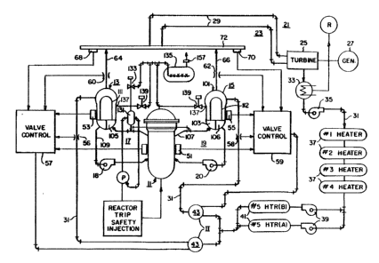
Fig. 1 is a diagrammatic view s~howing a nuclear-
reactor power plant in accordance with ~ invention and
which serves in the practice of the method of this
invention;
Fig. 2 is a view in lonyitudinal section, predom-
inantly diagrammatic, showiny a steam generator included in
the apparatus shown in Fig. l;
Fig. 3 is a diagrammatic view enlarged of the
portion of the apparatus shown in Fig. 1 which serves to
drain liquid from the shell side of a steam generator in
the practice of this invention; and
Fig. 3~shows typical levels of the liquid within
a steam generator. These levels are shown for the purpose
of aiding those skilled in the art in understanding this
invention and not with any intention of in any way re-
stricting the scope of this invention.
DESCRIPTION OF TEIE PREFERRED EMBODIMENT
AND PRACTICE OF INVENTIOM
The plant shown in the drawings is a power-supply
apparatus including a nuclear reactor 11 in thermal heat-
exchange relationship with a plurality of steam generators
13 and 15. A primary loop 17 and 19 respectively, each
including a pump 18 and 20, thermally interconnect the
reactor 11 and each of the generators 13 and 15. Coolant,
typically pressurized water at about 2000 psi, flows
through the core (not shown) of the reactor 11 and through
each of the generators 13 and 15. The heat derived by each
primary loop 17 and 19 from the core vaporizes the water in
each generator 13 and 15. A secondary loop 21 and 23 is
assGciated with each generator 13 and 15, respectivel~.
j7
8 - 52,131
While this invention is uniquely suitable for
steam-driven apparatus, the reference to "water" and "steam"
in this application is not intended to limit this invention.
To the extent that this invention is applicable to power
generators for example driven by fluids liquid sodium,
other than water, such application is within the lntended
scope of equivalents -thereof and the use of words "water"
and "steam" in this application and its claims, used in the
interest of convenience , is intended to include within its
scope such other fluids to the extent that this invention
is applied to plants using such other ~luids.
The plant shown in the drawings also includes
a turbine 25 and an electrical generator 27 driven by the
turbine 25. Each secondary loop 21 and 23 includes a first
branch 29 for supplying steam from each steam generator 13
and 15 to drive the turbine 25, and a second branch 31 for
supplying feedwater from the turbine 15 to the correspond-
ing steam generators 13 and 15. common to the branches 31
is a condenser 33 for condensing the fluid from the turbine
25, a condensate pump 35 and a plurality of heaters 37.
Each feedwater branch 31 also includes a feedwater pump 39,
a heater 41, and a valve unit 43. The valve units 43 are
described in more detail in Cook ~S. Patent 4,424,186.
The nuclear reactor 11 includes conventional
sensor 51 for deriving a signal from the neutron flux
dependent on the power of the reactor. Each steam genera-
tor 13 and 15 includes sensors 53 and 55 for deriving
signals dependent on the secondary water level in the steam
generators 13-15. There are also a sensor 56 and 58 for
deriving signals measuring feedwater flow from the
feedwater lines 31, sensors 60 and 62 for deriving signals
measuring steam flow typically from the steam lines 64 and
66, and sensors 68 and 70 for deriving steam pressure
measurement typically from the steam header 72. The
signals from the sensors 51, 53 and 55, 56 and 58, 60 and
62 and 68 and 70 are supplied to respective valve controls
A
~2~
- 9 52,131
57 and 59. The valve controls 57 and 59 control the valves
in each feedwater line 31. The purpose and function of these
valve controls are described in detail in Cook. They concern
this invention only colaterally.
Each steam generator 13~15 (Fig. 2, 3) includes
a vessel or shell 101 having a-t the bottom an inlet plenum 103
and an outlet plenum 105. The plenums are separated by a wall
106. The hot leg 107 of a loop 17 or 19 is connected to the
inlet plenum 103 and the cold leg 109 of each loop is connected
to the outlet plenum 105. Coolant from the reactor 11 is cond-
ucted to the plenum 103 through the hot leg and away from the
plenum 105 back to the reactor 11 through the cold leg 109.
The plenums 103 and 105 are spanned by, and are in communication
through, a plurali-ty of U-tubes 111 of a tube assembly 112.
The tube assembly 112 includes atub~sheet 114 into which the
ends of the tubes are sealed. The tube sheet 114 ex-tends across
the vessel 101 and is sealed pressure-tight along its periphery
to the inner surface of the vessel. The upper surface of the
tukesheet 114 is the base from which the levels shown in Fig. 3
are measured. The plenums 103 and 105 are interconnected by
the U-tubes 111 (or straight through tubes). The tubes 111
conduct the coolant through the shell 101 i.e., the generator
transferring heat to the feedwater 113 to generate the steam
for driving turbine 25. The feedwater 113 is supplied to the
steam generator 13-15 through line 31. The purpose of this
invention is to enable the operator to deal effectively with
the emergency which arises when one or several of the tubes
111 is ruptured, particularly where one or more of the tubes
111 is severed, and radioactive coolant is injec-ted into the
water 113.
The steam generator 13-15 also includes a shell
115 ~Fig. 2) which separates the annular region 117 into which
the feedwater flows from the region 119 where the steam is gen-
erated. The region 117 is called the down-comer and the region
113 the boiling region. Depending on the conditions in the
boiling region 119 and in the downcomer 117 the feedwater 113
flows bac~ and forth between these regions as shown by the
arrows 120, 121 and 123 through the open bottom of shell 115
~,~
57
- 10 - 52,131
and from the steam separators 124. The portion of the steam
generator including -the plenums 103, 105 and the tube assem-
bly 112 is sometimes referred to as the "coolant side" or the
"primary" of the s-team generator and the portion of the s-team
generator con-taining the water 113 and the steam, is some~
times referred to as the "shell side" or "secondary" of the
generator. The shell side of the steam generator contains
water and steam. This mixture is sometimes referred to as
"fluid".
The plant shown in the drawings also includes a
pressurizer 131 (Fig 1). The pressurizer 131 is connected
to the loops 17 and 19, to maintain the pressure of the cool-
ant at the required magnitude. The pressurizer 131 (Fig. 1)
is connected through valve means ]33 to a pressurizer relief
tank 135. When the pressure in the pressurizer 131 exceeds
a predetermined magnitude, water is discharged into relief
tank 135 through valve means 133. A pressure sensor P is
also connected to the pressurizer 131. On substantial red-
uction in pressure in the pressurizer automatic-reactor trip
and safety injection are enabled. The reactor 11 is deacti-
vated by the insertion of the control rods into the core and
by the addition of shim to the coolant and the injection of
water into the core and coolant loops 17 and 19 is enabled
to preclude overheating of the core. The reduction of press-
ure is also indicated on the indicator panel (not shown)of the plant. The radioactivity of t~e air ejected from
the condenser 33 as it is evacuated is also monitored by a
sensor R. The magnitude of radioactivity is indicated on
the indicator panel.
q'he shell side of each steam generator 13-15
is, in accordance with this invention, connected, through
a nozzle 137 and valve means 139, to the pressurizer relief
tank 135 (Fig. 3). The valve means 13~ includes at least
four valves 141, 143, 145, 147 (Fig. 3). Valves 141 and 145
are normally open and valves 143 and 147 are normally closed.
~2 ~i7
~ 52,131
Valves 141 and 143 are connected in series in one branch
and valves 145 and 147 are connected in series in a second
branch in parallel with the one branch. Each valve 141 to
147 is operable by a separate motor M. Two power trains
149 and 151 are provided for operating the motors M. Power
train 149 is identified as A and power train 151 as B.
Valves 141 and 147 are operated by power train 149 and valves
143 and 145 are operated by power train 151. This connection
of the valves 141 through 147 assures that if one power train
fails the other power train will be available to close or re-
open a valve between the shell side of the steam generator
and the pressurizer relief tank. For example assume that when
the valve means 139 is to be opened power train A is disabled.
Powertrain B will then serve to open valve 143. Now assume
that after valve 143 has been opened it becomes necessary to
reclose valve means 139 but power train B has failed while
power train A is in operation. Power train A will then serve
to close valve 141. Conversely if power train B fails, power
train A will serve to open valve 147 and if power train A
fails after valve 147 is opened, power train B will serve to
close valve 145. The regulations governing nuclear reactor
power plants do not contemplate that both power train A and
power train B will fail at the same time.
The valve means 139 is manually operable. The
operator can vary the opening in the valve means and thus
~4~
12 52,131
control the level of the liquid in a s-team generator 13-15
by the flow through the valve means.
Each secondary-water sensor 53-55 includes
subsensors over two level ranges Ll and L2 (Fig. 3). The
subsensors I,l and L2 sense the level of the liquid in each
steam genera-tor 13-15 above a predetermined level, typically
438 inches above the tube sheet as indicated in Fig. 3. Ll
senses and indicates the level of the liquid in steam
generator 13-15 up to the height of the head-to-shell weld
line, typically 650 inches above the tubesheet 114.
Su~sensor Ll thus senses the level at which the valve means
139 should be opened. Subsensor L2 senses the level of the
liquid between the predetermined level above the tubesheet
114 and an intermediate level, indicated in Fig. 3 as 566
inches above the tubesheet. Subsensor L2 is the normal
sensor which is included in a nuclear-reactor plant for
control and shut-down purposes responsive to the level of
the liquid in the steam generator 13-15. In the interest of
precision its range is limited so that it only senses up to
a level, typically 566 inches, below the level at which the
valve means 139 should be opened. As is stated subsensor Ll
senses and indicates that the level, typically 588 inches,
at which valve means 139 should be opened has been reached.
Subsensor L2 is connected to power trains 149 and 151
through an interlock 153. If, during the emergency, there
is a maloperation so that the level of ~he liquid in a steam
generator 13-15 drops to a height at which steam might flow
through nozzle 137, this interlock 153 operates to reclose
the valve means 139. The levels measured by subsensors Ll
and L2 are also transmitted to indicators 155 and 157.
On the occurrence of a rupture in one or more
tubes 111, coolant is injected into the liquid 113 in one
of the steam generators 13-15. The radioactivity sensor R
transmits an indication of increased radioactivity warning
the operator that a rupture may have occurred. The pres-
sure in pressurizer 131 is reduced and the reactor is
tripped and the safety injection is enabled. The operator
57
13 52/131
directs his at-tention to the level indications of subsensor
Ll of the severa] steam generators 13-15. The defective
steam yenerator is identified when the level of the liquid
in its shell reaches a predetermined height, typically 538
inches which is above the "normal level" 502 inches above
the tube sheet for example. At this point an alarm is
sounded for the defective generator~ The operator now
prepares to open the valve means 139. The value means is
opened when the level of the liquid in the defective steam
generator 13-15 reaches a predetermined height, typically
588 inches. This height is reached about 30 minutes, or
other mandated interval, after the primary-tube rupture.
The operator now opens the valve means and controls the
outflow so as to control the level of the liquid in the
shell. If control is 1ost so that the level drops to a
height at which steam may be ejected through nozzle 137,
the interlock 153 is operated and the valve means 139 is
closed. As the water flows into pressurizer relief tank
135, the pressure in the tank builds up until rupture disc
159 is opened discharging water from tank 135 into contain-
ment sump 161. The reactor plant is ultimately completely
shut down so that remedial action can be taken.
While preferred practice and a preferred embodi-
ment of this invention have been disclosed herein,
modifications thereof are feasible.