Language selection

Search

Patent 1264456 Summary

Third-party information liability

Some of the information on this Web page has been provided by external sources. The Government of Canada is not responsible for the accuracy, reliability or currency of the information supplied by external sources. Users wishing to rely upon this information should consult directly with the source of the information. Content provided by external sources is not subject to official languages, privacy and accessibility requirements.

Claims and Abstract availability

Any discrepancies in the text and image of the Claims and Abstract are due to differing posting times. Text of the Claims and Abstract are posted:

  • At the time the application is open to public inspection;
  • At the time of issue of the patent (grant).
(12) Patent: (11) CA 1264456
(21) Application Number: 503981
(54) English Title: CARRIER RAIL FOR OVERHEAD CONVEYORS
(54) French Title: RAIL PORTEUR POUR TRANSPORTEURS AERIENS
Status: Expired
Bibliographic Data
(52) Canadian Patent Classification (CPC):
  • 198/12.09
(51) International Patent Classification (IPC):
  • B61B 3/02 (2006.01)
  • E01B 25/24 (2006.01)
(72) Inventors :
  • VOLKSTORF, HANS-HERMANN (Germany)
  • FELDMEIER, EDWIN (Germany)
  • WALTI, MARC (Switzerland)
(73) Owners :
  • DIGITRON TRANSLIFT AG (Switzerland)
(71) Applicants :
(74) Agent: OSLER, HOSKIN & HARCOURT LLP
(74) Associate agent:
(45) Issued: 1990-01-16
(22) Filed Date: 1986-03-13
Availability of licence: N/A
(25) Language of filing: English

Patent Cooperation Treaty (PCT): No

(30) Application Priority Data:
Application No. Country/Territory Date
G 85 08 070.5 Germany 1985-03-19

Abstracts

English Abstract


CARRIER RAIL FOR OVERHEAD CONVEYORS

ABSTRACT OF THE DISCLOSURE

A carrier rail for overhead conveyors includes an
upper and a lower flange connected together by a web.
Angled profiles are disposed on at least one side of the web
and are spaced apart interiorly of the flanges. The
profiles and the web cooperatively define together at least
two grooves therein. Each of the two grooves has an opening
and the grooves are directed so that the openings face each
other. The angled profiles are preferably integrally formed
with the web, and form right angles with the web. Two
angled profiles may be disposed on each side of the web, and
form four grooves with the web.


Claims

Note: Claims are shown in the official language in which they were submitted.

THE EMBODIMENTS OF THE INVENTION IN WHICH AN EXCLUSIVE
PROPERTY OR PRIVILEGE IS CLAIMED ARE DEFINED AS FOLLOWS:

1. A symmetrical, double T carrier rail for overhead
conveyors comprising:
an upper solid and a lower solid flange connected
together by a solid web; and
two opposed pairs of angled profiles integrally
formed with said web at right angles thereto with one
pair disposed on each side of said web, each angled
profile being spaced interiorly from said upper and lower
flanges, each of said angled profiles and said web
cooperatively defining a groove therebetween, and wherein
said grooves on the same side of said web face each
other.


Description

Note: Descriptions are shown in the official language in which they were submitted.


BACKGROUND OF THE INVENTION

The i.nvention relates to a carrier rail for
overhead conveyors. More parti.cularly, it relates to a
carrier ra.il for overhead conveyors which includes an upper
and a lower flange connected together by a vertical web.


In German Gebrauchsmuster 84 04 118.4 a carrier
rail oE this type is described, in which on the under- or
;.nnerside of the flanges, outside of the pressure plane
developed upon bending of the ra.il, and on both sides of the
web, longitudinally extending ledges are provided to form
: longitudinal grooves between the web and ledges. These
longitud.inal grooves serve to secure the fastening devices
for electrical conductorst and accurate guide or control
markings or the like, without changing the rail.


Accordingly, it .is an:object of the present
invention to provide an improved carrier rail which has
complete independence from the longitudinal grooves of the
flanges, so as to prevent a compressing or tensioning of the
longitudinal grooves on bending of the rail, or the curves
corresponding to the course of the rail.


:~ SUMMARY OF THE INVENTION

The foregoing and related objects are readily

attained in a carrier rail of the type described above
wherein at one or both~sides along the two faces of the web
angled profiles are arranged at a distance from the
underside of the flanges, to form two or four grooves.


5~i

The invention affords the signif.icant advantage
that the long;.tudinal grooves are not compressed on bending
the curves corresponding to the course of the rai.l. A
further feature of the .invention is to use the web surfaces
between upper and lower flange, and the angled profiles
arranged on the web, for mounting track measuring systems,
for example, toothed racks, adhesive f.ilms having a distance
grating or screen, or similar systems, and thereby to

control a veh.icle traveling on the prof.ile.


Accord.ing to a preferred embodiment, each two
grooves on one slde of the web are directed so that their
openings are opposed, i.e., the opening of the groove of the
lower flange faces upwards and the opening of the groove of
the upper flange faces downwards. The angled profiles may
~; be formed integral with the web and, prefe~rably, may form a
r.ight angle to the web surfaces.


Other objects and features of the present invention
w.ill become apparent from the following detailed description
consldered in connection with the accompanying drawing,
which discloses one embodiment of the invention. It is to
be understood that the drawing is to be used for the purpose
of illustration only,~and not as a definition of the limits
of the lnvention.


BRIEF DESCRIPTION OF THE DRAWING
~: :
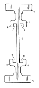
The drawing is a cross-sectional view of the

3 carrier rail accord.ing to the invention.

~lX~i4~5~;

DETAILED DESCRIPTION OF THE PREFERRED EMBODIMENT


Turning now in particular to the appended drawing,
therein illustrated ls a novel carrier rail, embodying the
present invention, which includes an upper flange 1 and a
lower flan~e 2, which are joined together by a vertical web
3. At a distance from upper flange 1, two angled profiles 4
and 5 are arranged on web 3, and form longitudinally-
extending grooves 6,7 with web 3. In the same way, two
10angled profiles 8,9 are arranged at a distance from lower
flange 2, and form two longitudinally~extending grooves
10,11 on opposite sides of the web. Grooves 6,10 or 7,11
are arranged so that their openings are opposite to each
other. Angled profiles 4,5 and 8,9 can be formed integral
wlth web 3 and the two flanges 1 and 2, respectively. In
the specific embodiment illustrated in the drawing, angled
profiles 4,5 and 8,9 form a right angle to web 3.
Longitudinal grooves 6,7 and 10,11 may be used to easily
attach electrical conductors, guide controls, joint
connectors, overhead suspens~ons, etc., to the rail.


Thus, while only a single embodiment of the present
~invention has been shown and described, it will be obvious
; ~that many changes and modifications may be made thereunto,
without departing from the spirit and scope of the invention.


,,


-- 3 --


: ~ ., .`.", ~ , :
.

Representative Drawing
A single figure which represents the drawing illustrating the invention.
Administrative Status

For a clearer understanding of the status of the application/patent presented on this page, the site Disclaimer , as well as the definitions for Patent , Administrative Status , Maintenance Fee  and Payment History  should be consulted.

Administrative Status

Title Date
Forecasted Issue Date 1990-01-16
(22) Filed 1986-03-13
(45) Issued 1990-01-16
Expired 2007-01-16

Abandonment History

There is no abandonment history.

Payment History

Fee Type Anniversary Year Due Date Amount Paid Paid Date
Application Fee $0.00 1986-03-13
Registration of a document - section 124 $0.00 1987-03-30
Maintenance Fee - Patent - Old Act 2 1992-01-16 $50.00 1991-11-14
Maintenance Fee - Patent - Old Act 3 1993-01-18 $50.00 1992-11-19
Maintenance Fee - Patent - Old Act 4 1994-01-17 $50.00 1993-12-08
Registration of a document - section 124 $0.00 1994-08-23
Maintenance Fee - Patent - Old Act 5 1995-01-16 $75.00 1994-11-30
Maintenance Fee - Patent - Old Act 6 1996-01-16 $75.00 1995-10-23
Maintenance Fee - Patent - Old Act 7 1997-01-16 $75.00 1996-12-18
Maintenance Fee - Patent - Old Act 8 1998-01-20 $75.00 1997-12-15
Maintenance Fee - Patent - Old Act 9 1999-01-18 $75.00 1999-01-05
Registration of a document - section 124 $100.00 1999-03-15
Maintenance Fee - Patent - Old Act 10 2000-01-17 $100.00 1999-12-14
Maintenance Fee - Patent - Old Act 11 2001-01-16 $100.00 2001-01-15
Maintenance Fee - Patent - Old Act 12 2002-01-16 $100.00 2002-01-07
Maintenance Fee - Patent - Old Act 13 2003-01-16 $100.00 2003-01-07
Maintenance Fee - Patent - Old Act 14 2004-01-16 $200.00 2003-12-23
Back Payment of Fees $225.00 2004-12-22
Maintenance Fee - Patent - Old Act 15 2005-01-17 $225.00 2004-12-22
Back Payment of Fees $225.00 2005-12-23
Maintenance Fee - Patent - Old Act 16 2006-01-16 $225.00 2005-12-23
Owners on Record

Note: Records showing the ownership history in alphabetical order.

Current Owners on Record
DIGITRON TRANSLIFT AG
Past Owners on Record
BLASER, RENE
DIGITRON AG
FELDMEIER, EDWIN
TRANSLIFT GESELLSCHAFT FUR HEBE- UND FORDERANLAGEN MBH
VOLKSTORF, HANS-HERMANN
WALTI, MARC
Past Owners that do not appear in the "Owners on Record" listing will appear in other documentation within the application.
Documents

To view selected files, please enter reCAPTCHA code :


To view images, click a link in the Document Description column. To download the documents, select one or more checkboxes in the first column and then click the "Download Selected in PDF format (Zip Archive)" or the "Download Selected as Single PDF" button.

List of published and non-published patent-specific documents on the CPD .

If you have any difficulty accessing content, you can call the Client Service Centre at 1-866-997-1936 or send them an e-mail at CIPO Client Service Centre.


Document
Description 
Date
(yyyy-mm-dd) 
Number of pages   Size of Image (KB) 
Representative Drawing 2001-10-02 1 5
Description 1993-09-15 3 128
Drawings 1993-09-15 1 32
Claims 1993-09-15 1 32
Abstract 1993-09-15 1 25
Cover Page 1993-09-15 1 33
Fees 2003-01-07 1 46
Fees 1999-01-05 1 65
Fees 2001-01-15 1 55
Fees 2002-01-07 1 72
Fees 1997-12-15 1 59
Fees 1999-12-14 1 56
Fees 2001-01-15 1 53
Fees 1999-12-14 1 62
Fees 1999-01-05 1 60
Fees 1997-12-15 1 58
Fees 1996-12-18 1 51
Fees 1995-10-23 1 49
Fees 1994-11-30 1 49
Fees 1993-12-08 1 68
Fees 1992-11-19 1 54
Fees 1991-11-14 1 53