Note: Descriptions are shown in the official language in which they were submitted.
~2~45~
BALL AND SOCKET BEARING FOR ARTIFICIAL JOINT
BACKGROUND OF THE INVENTION
1. Field of the Invention
This invention relates to artificial joints and in
particular to artificial joints of the ball and socket
type.
2. Description of the Prior Art
As is well known in the art, artificial hip and
shoulder joints conventionally employ bal~ and socket
articulations. The socket is embedded in one bony
structure, for example, the pelvis for a hip
reconstruction. The ball is attached to an arm composed
of a neck and a stem or shaft, the stem or shaft being
~mbedded in another bony structure, for example, the
femur for a hip reconstruction.
A number of methods are known for retaining the ball
in the socket. In the most common method, referred to
herein as the "semi-constrained" construction, the
patient's own anatomy, i.e., his muscles, tendons and
ligaments, are used to retain the ball within the socket.
For this construction, a hemispherical socket typically
is used which allows the ball and its attached arm the
maximum amount of movement without contact of the arm
with the edge of the socket. The surgeon, when
installing such a semi-constrained joint, aligns the ball
and socket as closely as possible with the patient's
natural anatomy so that the patient's movements do not
ter.d to dislocate the ball from the joint. As a general
proposition, such precise alignment is easiest the first
time an artificial joint is placed in a patient.
Subsequent ~-econstructions are much more difficult to
align because of deterioration of anatomical landmarks as
a result of the first operation, the healing process
~.,
1 ~2~ ~ S ~ ~
af~er the op~ration and changes in the anatomy caused by
the presence of the artificial joint.
In order to increase the inherent stability against
dislocation of such semi-constrained constructions~ it
has become conventional to add a cylindrical portion to
the hemispherical socket to make it deeper. Although the
ball is not physically constrained ~y the socket by this
adjustment, the ball does have further to travel than if
just a hemisphere had been used and thus some reduction
in the propensity towards dislocation is achieved. Ball
and socket joints of this type generally provide an arc
or range of motion of approximately 115 when a 28mm
diameter sphere is used and the socket is made a few
millimeters deeper than a hemisphere. Larger ranges of
motion can be obtained by keeping the size of the arm
attached to the ball constant and increasing the diameter
of the ball. In this way, the angular extent of the arm
relative to the ball becomes smaller. In the limit, if
the ball could be made progressively larger and larger, a
range of motion of 180 could be achieved. In practice,
however, the largest sphere in common use in artificial
joints, and in particular artificial hip joints, has a
diameter of 32mm and provides a range of motion of
appro~imately 120. It should be noted, however, that
such larger sphere sizes are not universally favored
because frictional torque increases with diameter.
~ recent s~udy by the Mayo Clinic, which appeared in
December, 1982 edition of The Journal of Bone and Joint
Surgery, reported a dislocation frequency of 3.2% for
10,500 hip joint implant procedures using the semi-
constrained construction. Such dislocatlons essentially
make the patient immobile and can necessitate a second
operation. As discussed above, the critical alignment
required for the semi-constrained construction is even
more difficult to achieve when a second implantation is
performed. Accordingly, even higher dislocation
501
--3--
frequencies are encountered for second and subsequent
implantations.
An alternative to the semi-constrained construction
is the constr~lction wherein the ball is physically
constrained within the socket. In this construction, a
spherically-shaped bearing surrounds the ball and serves
as the soc~et. The bearing is attached to a fixation
element which is embedded in, for example, the patient's
pelvic bone. The bearing encompasses more than one-half
of the ball and thus constrains the ball and its attached
arm from dislocation.
The bearing is typically made from plastic, such as
ultra-high molecular weight polyethylene (UHMWPE), or
metal. For plastic bearings, the ball and bearing are
usually assembled by forcing the bearing over the ball.
The more of the ball which is encompassed by the bearing,
the greater the required assembly force, and the greater
the constraining force to prevent postoperative
dislocation of the joint. In addition, the more that the
bearing encompasses the ball J the smaller the range of
motion for the ball prior to contact of the bearing with
the arm attached to the ball.
An example of a constrained artificial joint
employing a plastic bearing is shown in Noiles, U.S.
Patent 3,996,625. As can be seen in Figure 1 of this
patentl a plastic bearing 17 fitted with a metal
reinforcing band (un-numbered) extends beyond the
diameter of ball 24 so as to physically constrain the
ball within the bearing. The bearing itself is attached
to fixation element 12. The metal reinforcing band is
assembled over the lip of the opening of bearing 17 after
that bearing has been forced over sphere 24. The
reinforcing band increases the force required to
dislocate the joint. In practice, the design shown in
Figure 1 of U.S. Patent 3,996,625 has been found to
provide a range of motion of approximately 85 when a
~26a~S~l~
~,
sphere diameter of 28mm is used and to resist direct
dislocating forces of several hundred pounds.
For constrained constructions such as that shown in
U.S. Patent 3,996,625, it has been found in use that a
dislocating fo~ce is crea~ed when the neck of the arm
attached to ~he ball impinges on the rim of the bearing.
Because of the leverage associated with the arm and the
long bone of the patient to which it is attached, e.g.,
the patient's femur, the dislocating force produced when
the neck contacts the rim of the bearing can be
considerable. For example, a force on the order of 25
pounds applied to a patient's leg can produce a
dislocating force of over several hundred pounds because
of the leverages involved. This type of dislocation
force can be avoided by geometrically aligning the
artificial joint with the patient's anatomy so that the
neck does not come in contact with the rim ~f the bearing
during normal motion of the patient's limb. That is, the
leverage based dislocation forces can be avoided in the
same way as dislocations are avoided in the
semi-cons~rained construction, i.e., through precise
alignment of the artificial joint with the natural
anatomy of the patient. Unfortunately, as is apparent
from the geometry of the situation, the more the socket
bearing encompasses the ball, the greater the restraining
force on the ball, but at the same time the less the
range of motion prior to the neck impinging upon the edge
of the bearing to create undesired leverage. In
practice, artificial hips having the construction shown
in U.S. Patent 3,996,625 have been found to suffer
dislocation due to the leverage effect in fewer than 0.5%
of the implantations performed. This is significantly
better than the 3.5% dislocation frequency reported in
the Mayo Clinic study discussed above, but an even lower
dislocation frequency is obviously desirable.
A constrained construction using a metal socket
bearing is shown in Noiles, U.S. Reissue Patent 28,895
45~1
--5--
(reissue of U.S. Patent 3,848,272). This construction
provides appro~imately a 90 range of motion when the
sphere diameter is 28mm. In a practical sense, the metal
bearing can be said to be non-dislocatable. The force
required to extract the metal sphere from the enclosing
metal socket bearing is more than several thousand
pounds. Accordingly, in use, rather than the metal ball
dislocating from the metal socket bearing, any overly
severe dislocating leverage will cause the fixation
element to be disrupted from the bone in which it has
been embedded.
As a general proposition, metal balls in metal
socket bearings are used in only a minority of joint
reconstructions because the medical profession is not in
agreement that a metal sphere in a metal bearing is as
biologically acceptable as a metal sphere in a UHMWPE
plastic bearing, even though clinical use over 15 years
has failed to show the metal to metal joint to be
inferior to a metal to plastic joint.
A third type of artificial ball and socket joint,
referred to as an endoprosthesis, eliminates the fixation
element associated with the socket and simply uses a ball
surrounded by a plastic socket bearing in a spherical
metal head, which head is placed in the patient's natural
socket but not secured to bone. For this construction,
the ball can rotate within the bearing up to the rim of
the bearing (the bearing is greater than a hemisphere so
as to be retained on the ball), and then the bearing and
its attached head rotates in the patient's socket. As
with the semi~constrained construction, anatomical
alignment is used to avoid dislocations, in this case
between the metal head and the natural socket.
In ~iew of the foregoing, it is apparent that in
semi-constrained and endoprosthesis hip joints,
reconstructive geometry of the prosthetic components is
critical in ensuring the stability of the prosthesis
against dislocation. Moreover, in ball and socket
~26~0~
-- 6 --
constructions which constrain the elements against
dislocation, the range of motion inherent in the
prosthesis is reduced and thus because of the possibility
of leverage type dislocations, similar demands are placed
on the surgeon to establish the geometry of the
reconstruction within rather narrow limits.
~X~6~5~L
-- 7
UMMARY OF THE INVENTION
In accordance with one aspect of the invention, there is
pxovided a ball and socket joint for implantation in a
patient's body comprising a ball portion and a socket
portion,
the ball portion including:
a ball; and
first fixation means for attachment to a
first bony structure, said fixation means ~eing
connected to said ~all by a neck; and
the socket portion including:
a bearing for receiving the ball, said bearing
surrounding a portion of the ball, the ball
with the neck being free to move within the
bearing in a plurality of directions;
second fixation means for attachment to a
second bony structure, said second fixation means
having a cavity for receiving the bearing, said
cavity having an opening defining a first plane
through which the bearing enters the cavity; and
means for securing the bearing to the second
fixation means in any one of a plurality o
selectable orientations after the second fixation
means has been attached to the second bony
structure, said plurality of selectable
orientations being angularly displaced from one
another about an axis which is perpendicular to the
first plane;
the bearing being non-symmetric with regard to rotation
about said axis in that the angular range of motion of
the ball with the neck within $he bearing prior to
impingement of the neck with the socket portion of the
joint is smaller in at least one first direction than in
at least one other direction, the angular range of
motion i.n a particular direction being the angular
.
- 8~
excursion of the neck in that direction measur2d ~rom an
axis which is perpendicular to the first plane and
passes through the center of the ball, said lack o~
symmetry making at least one of the selectable angular
oriantations of the bearing more preferred for
physiological reasons than others of said angular
orientations, said means for securing allowing said
bearing to be secured to said second ~ixation means in
such a preferred orientation after said second ~ixation
means has been attached to the second bony structure.
In accordance with a further aspect of the invention,
there is provided a prosthesis for implantation in a
patient's body as part of a ball and socket joint, said
joint including a ball portion and a socket portion, said
prosthesis forming the socket portion of the ~oint and
comprising:
a bearing for receiving the ball portion of the ball and
socket joint, said ball portion including a ball connected
to a neck, said bearing surrounding a portion of the ball,
and the ball with the neck being free to move within the
bearing in a plurality of directions in the assembled joint;
fixation means for attachment to a bony structurer said
fixation means having a cavity for receiving the bearing,
said cavity having an opening de~ining a first plane through
which the bearing enters the cavity; and
means for securing the bearing to the fixation means in
any one of a plurality of selectable orientations after the
fixation means has been attached to the bony structure, said
plurality of selectable orientations being angularly
displaced from one another about an axis which is
perpendicular to the first plane;
the bearing being non-symmetric with regard to rotation
about said axis in that, in the assembled joint, the angular
range of motion of the ball with the ne~k within the bearing
prior to impingement of the neck with the socket portion of
the joint is smaller in at least one first direction than in
5(~l
at least one other direction, the angular range of motion in
a particular direction being the angular excursion of the
neck in that direction mea.sured from an axis which i5
perpendicular to the first plane and passes through the
center of the ball, said lack of symmetry making at least
one of the selectable angular orientations of the bearing
more preferred for physiological reasons than others of said
angular orientations, said means for securing allowing said
bearing to be secured to said fixation means in such a
preferred orientation after said fixation means has been
attached to the bony structure.
In accordance with yet a further aspect of the the
invention there is provided a ball and socket joint for
implantation in a patient's body comprising a ball portion
and a socket portion,
the ball portion including:
a ball; and
first fixation means for attachment to a
first bony structure, said fixation means being
connected to said ball; and
the socket portion including5
a bearing for receiving the ball;
second fixation means for attachment to a
second bony structure, said second fixation means
having a cavity Por receiving the bearing, said
cavity having an opening defining a plane through
which the bearing enters the cavity; and
means for securing the bearing to the second
fixation means in any one of a plurality of
selectable orientations after the second ~ixation
means has been attached to the second bony
structure, said plurality of selectable
orientations being angularly displaced from one
another about an axis which is perpendicular to the
plane defined by the opening of the cavity of the
second fixation means, said means for securing
comprising bayonet spaces and lugs;
~Zl604S~
the beariny heiny non-symmetric with regard to rotation
about said axis and said lack of symmetry making at
least one of the selectable angular orientations of the
bearing more preferred for physiological reasons than
others of said angular orientations, said means for
securing allowing said bearing to be secured to said
second fixation means in such a preferred orientation
after said second fixation means has been attached to
the second bony structure.
In accordance with yet a further aspect of the
invention, there is provided a ball and socket joint for
implantation in a patient's body comprising a ball portion
and a socket portion,
the ball portion including:
a ball: and
first fixation means for attachment to a
first bony structure, said fixation means being
connected to said ball; and
the socket portion including:
a bearing for receiving the ball;
second ~ixation means for attachment to a
second bony structure, said second fixation means
having a cavity for receiving the bearing, said
cavity having an opening defining a plane through
which the bearing enters the cavity; and
means for securing the bearing to the second
fixation means in any one of a plurality of
selectable orientations after the sPcond fixation
means has been attached to the second bony
structure, said plurality of selectable
orientations being angularly displaced from onP
another about an axis which is perpendicular to the
plane defined by the opening of the cavity of the
second fixation means;
the bearing being non symmetric with regard to rotation
about said axis and said lack of symmetry making at
,. ..
~z~o~
- l~A
least one of the selectable angular orientations of the
bearing more preferred for physiological reasons than
others of said angular orientations, said means for
securing allowing said bearing to be secured to said
second fixation means in such a preferred orientation
after said second fixation means has been attached to
the second bony structure, the means for securing
including two coaxial pin members and the bearing
including two coaxial cylindrical surfaces which receive
the pin members, the pin members and the cylindrical
surfaces allowing the bearing to rotate within the
cavity of the second fixation means about a single axis,
said single axis being orthogonal to the axis which
defines the plurality of selectable angular
orientations, the orientation of the single axis with
respect to the anatomy of the patient's body making at
least one of the selectable angular orientations of the
bearing more preferred for physiological reasons than
others of said angular orientations.
In accordance with yet a further aspect of the
invention, there is provided a ball and socket joint for
implantation in a patient's body comprising a ball portion
and a socket portion,
the ball portion including:
a ball; and
first fixation means for attachment to a
first bony structure, said fixation means being
connected to said ball; and
the socket portion including:
a bearing for receiving the ball;
second fixation means for attachment to a
second bony structure, said second fixation means
having a cavity for receiving the bearing, said
cavity having an opening defining a plane through
which the bearing enters the cavity; and
o~
- ln~ -
means for securing the bearing to the second
fixation means in any one of a plurality of
selectable orientations after the second fixation
means has been attachad to the second hony
structure, said plurality of selectable
orientations being angularly displaced from one
another about an axis which is perpendicular to the
plane defined by the opening of the cavity of the
second fixation means;
the bearing being non-symmetric with reyard to rotation
about said axis and said lack of symmetry making at
least one of the selectable angular orientations of the
bearing more preferred for physiological reasons than
others of said angular orientations, said means for
securing allowing said bearing to be secured to said
second fixation means in such a preferred orientation
after said second fixation means has been attached to
the second bony structure, the bearing including a lip
to xestrain dislocations of the ball from the bearing,
tihe orientation of said lip with respect to the anatomy
of the patient's body making at least one of the
selectable angular orientations of the bearing more
preferred for physiological reasons than others of said
angular orientations.
In accordance with yet a furthar aspect of the
invention, there i.s provided a prosthesis for implantation
in a patient's body comprising:
a bearing for receiving the ball portion of a ball and
socket ~oint;
fixation means for attachment to a bony structure, said
~ixation means having a cavity for receiving the bearing,
said cavity having an opening defining a plane through which
the baaring enters the cavity; and
means for securing the bearing to the fixation means in
any one of a plurality of selectable orientations after the
fixation means has been attached to the bony structure, said
,,~
s~
- 1 OC -
plurality of selectable orientations being angularly
displaced from one another about an axis which is
perpendicular to the plane defined by the opening of the
cavity of the fixation means, said means for securing comprising bayonet spaces and lugs;
the bearing being non-symmetric with regard to rotation
about said axis and said lack of symmetry making at least
one of the selectable angular orientations of the bearing
more preferred for physiological reasons than others of said
angular orientations, said means for securing allowing said
bearing to be secured to said fixation means in such a
preferred orientation after said fixation means has been
attached to the bony structure.
In accordance with yet a further aspect of the
invention, there is provided a prosthesis for implantation
in a patient's body comprising:
a bearing for receiving the ball portion of a ball and
socket joint;
fixation means for attachmerlt to a bony structure, said
fixation means having a cavity for receiving the bearing,
said cavity having an opening defining a plane through which
the bearing enters the cavity; and
means for securing the bearing to the fixation means in
any one of a plurality of selectable orientations after the
fixation means has been attached to the bony structure, said
plurality of selectable orientations being angularly
displaced from one another about an axis which is
perpendicular to the plane defined by the opening of the
cavity of the fixation means;
the bearing being non-symmetri.c with regard to rotation
about said axis and said lack of symmetry making at least
one of the selectable angular orientations o the bearing
more preferred for physiological reasons than others of said
angular orientations, said means for securing allowing said
bearing to be secured to said fixation means in such a
preferred orientation after said fixation means has been
sa)~
- 10D -
attached to the bony structure, the means for securing
including two coaxial pin members and the bearing including
two coaxial cylindrical surfaces which receive the pin
members, the pin members and the cylindrical surfaces
allowing the bearing to rotate w.i.thin the cavity of the
fixation means about a single axis, said single axis being
orthogonal to the axis which defines the plurality of
selectable angular orientations, the orientation of the
single axis with respect to the anatomy of the patient's
body making at least one of the selectable angular
orientations of the bearing more preferred for physiological
reasons than others of said angular orientations.
In accordance with yet a further aspect of the
invention, there is provided a prosthesis for implantation
in a patient's body comprising:
a bearing for receiving the ball portion of a ball and
socket joint;
fixation means for attachment to a bony structure, said
fixation means having a cavity for receiving the bearing,
said cavity having an opening defining a plane through which
the bearing enters the cavity; and
means for securing the bearing to the fixation means in
any one of a plurality of selectable orientations after the
fixation means has been attached to the bony structure, said
plurality of selectable orientations being angularly
displaced from one another about an axis which is
perpendicular to the plane defined by the opening of the
cavity of the fixation means;
the bearing being non-symmetric with regard to rotation
about said axis and said lack of symmetry making at least
one of the selectable angular orientations of the bearing
more preferred for physiological reasons than others of said
angular orientations, said means for securing allowing said
bearing to ba secured to said fixation means in such a
preferred orientation after said fixation means has been
attached to the bony structure, the bearing including a lip
~z~
- lOE -
to restrain dislocations of the ball from the bearing, the
orientation of said lip with respect to the anatomy of the
patient's body making at least one of the selectable angular
orientations of the bearing more preferred for physiological
reasons than others of said angular orientations.
In accordance with yet a further aspect of the
invention, there is provided a system for use in forming the
socket portion of an artificial ball and socket joint, said
ball and socket joint including a ball portion and a socket
portion, said ball portion including a ball connected to a
neckt said system comprising:
(a) fixation means for attachment to a bony structure;
(bj first bearing means for receiving the ball portion
of the ball and socket joint such that in the assembled
joint, the first bearing means (i) surrounds a portion of
the ball, (ii) locates the center of the ball at a
predetermined position relative to the fixation means, and
(iii) the ball with the neck is free to move within the
first bearing means in a plurality of directions;
(c) second bearing means for receiving the ball portion
of the ball and socket joint such that in the assembled
joint, the second bearing means (i) surrounds a portion of
the ball, (ii) locates the center of the ball at a
predetermined position relative to the fixation means, said
predetarmined position being substantially the same as the
predetermined position at which the first bearing means
locates the center of the ball, and (iii) the ball with the
neck is free to move within the second bearing means in a
plurality of directions; and
(d) securing means for interchangeably securing either
the first bearing means or the second bearing means to the
fixation means;
the first and second bearing means differing from one
another in that if the first bearing means is selected to
form the socket portion of the joint and is implanted in a
patient, khe ball will be subject to more restraint so that
~l2¢~450~
- lOF -
the joint will be less likely to dislocate than i~ the
second bearing means is selected and implanted in that
patient.
In accordance with yet a further aspect of the
invention, there is provided a system for use in forming an
artificial ball and socket joint, said system comprising:
a ball portion including a ball and first fixation means
for attachment to a first bony structure, said fixation
means being connected to said ball by a neck; and
a socket portion including:
(a) second fixation means for attachment to a
second bony structure; and
(b) first bearing means ~or receiving the ball such
that in the assembled joint, the Eirst bearing means (i)
surrounds a portion of the ball, (ii) locates the center of
the ball at a predetermined position relative to the second
fixation means, and ~iii) the ball with the neck is free to
move within the first bearing means in a plurality of
directions;
(c) second bearing means for receiving the ball
such that in khe assembled joint, the second bearing means
(i) surrounds a portion of the ball, (ii) locates the center
of the ball at a predetermined position relative to the
second fixation means, said predetermined position being
substantially the same as the predetermined position at
which the first bearing means locates the center of the
ball, and (iii) the ball with th neck is free to move
within the second bearing means in a plurality o~
directions; and
(d) securing means for interchangeably securing
either the first bearing means or the second bearing means
to the second fixation means;
the first and second bearing means differing from one
another in that if the first bearing means is selected to
form the joint and is implanted in a patient, the ball will
be subject to more restraint so that the joint will be less
~ 2 ~ 5
~l~G-
likely to dislocate than if the second bearing means
is selected and implanted in that patient.
In accordance with yet a further aspect of the
invention, there is provided a ball and socket joint
for implantation in a patient's body comprising a
ball portion and a socket portion,
the ball portion including:
a ball; and
first fixation means for attachment to
a first bony structure, Qaid fixation means
being connected to said ball by a neck; and
the socket portion including:
a bearing for receiving the ball, said
bearing surrounding a portion of the
ball, the ball with the neck being
free to move within the bearing in a
plurality of directions;
second fixation means for attachment
to a second bony structure, said second
fixation means having a cavity for
receiving the bearing, said cavity having
an opening defining a first plane through
which the bearing enters the cavity; and
means for securing the bearing to the
second fixation means in any one of a
plurality of selectable orientations after
the second fixation means has been attached
to the second bony structure, said
plurality o~ selectable orientations being
angularly displaced from one another about
a first axis which is perpendicular to the
first plane;
the bearing being non~symmetric with regard to
rotation about the first axis and said lack of
O~L
-lOH-
symmetry making at least one o~ the selectable
angular ori~ntations of the bearing more
preferred or physiological reasons than o~hers
of said angular orlentations, said means for
securing allowing said bearing, when received in
the ca~ity, to be: 1) rotated within the cavity
about the first axis from any one of said
pl~lrality of selec~able angular orientations to
any other one of said plurality of selectable
orientations, and 2) locked to the second
fixation means in any one of said plurality of
selectable angular orientations, whereby the
bearing can be ro~a~ed to a more preferred
selectable oriPntation and locked to the second
fixation means in that orientation after the
second fixation means has been attached to the
second bony structure and after the bearing has
been received in the second fixation means'
cavity, said non-symmetry of the bearing about
the first axis being such that the angular range
of motion of the ball with the neck within the
bearing prior to impingement of the neck with
the socket portion of the joint is smaller in at
least one first direction than in at least one
other direction, the angular range of motion in
a particular direction being ~he angular
excursion of the neck in that direction measured
from an axis which is perpendicular to the first
plane and passes through the center of the ball,
3Q the orientation of the first direction with
respect to the anatomy of the patient's body
making the at least one selectable angular
orientation of the bearing more preferred for
physiological reasons than others of said
angular orientations.
.~
~Z~a~5(~
-lOI-
ln accordance with yet a further aspect of the
invention, ~here is provided a ball and socket
joint for implanting in the body comprising:
a ball;
first means for affixing the ball to bone
including a stem portion for implantation in bone and
a neck portion connecting the stem portion to the
ball;
a bearing member for receiving the ball;
second means for affixation to bone, said means
including a cavity which surrounds a portion of the
bearing member, said cavity having an opening which
defines a plane through which the bearing member
enters the cavity;
third means associated with the bearing member
and the second means for retaining the bearing member
in the cavity, said third means permitting the
bearing member to be inserted into and removed from
the cavity in at least one discrete initial position
and permitting the bearing member to be rotated while
seated in the cavity in either a clockwise or a
counterclockwise direction about an axis passing
through the cavity, said axis being substantially
perpendicular to the plane defined by the opening of
the cavity, said rotation of the bearing member
permitting the bearing member to be moved from said
at least one discrete initial position to any one of
a plurality of intermediate positions in which the
bearing member cannot be inserted or removed from the
cavity, and to be moved from any one of the plurality
of intermediate positions to at least one discrete
final position in which the bearing member may be
locked in position; and
fourth means for locking the bearing member in
said at least one discrete final position.
~ ,,,11 ,
~2645~)~
-lOJ-
In accordance with yet a further aspect of the
invention, there is provided apparatus for affixing a
socket bearing of an artificial ball and socket joint
to bone comprising:
(a) a body to be affixed to bone which includes
a cavity for receiving the socket bearing, said
cavity having an opening which defines a plane
through which the socket bearing enters the cavity;
(b) means for retaining the bearing in the
cavity, said means permitting the bearing to be
inserted into and removed from the cavity in at least
one discrete initial position and permitting the
bearing to be rotated while seated in the cavity in
either a clockwise or counterclockwise direction
about an axis passing through the cavity, said axis
being substantially perpendicular to ~he plane
defined by the opening of the cavity, said rotation
of the bearing permitting the bearing to be moved
from said at least one discrete initial position to
any one of a plurality of intermediate positions in
which the bearing cannot be inserted or removed from
the cavity and to be moved from any one of the
plurality of intermediate positions to at least one
discrete final position in which the bearing may be
locked in position; and
(c) means for locking the bearing in said at
least one discrete final position.
In accordance with yet a further aspect of the
invention, there is provided a ball and socket joint
for implanting in the body comprising:
a ball;
first means for af:fixing the ball ~o bone
including a stem portion for implantation in bone and
,,~ ~,,.
5~
~lOK-
a n~ck portion connecting the stem portion to the
ball;
a bearing member for receiving the ball;
second means for af~ixation to bone, said means
including a cavity which surrounds a portion of the
bearing member, said cavi~y having an opening which
defines a plane through which the bearing member
enters the cavity;
third means associated with the bearing member
and the second means for retaining the bearing member
in the cavity, said third means permitting the
bearing member to be inserted into and removed from
the cavity in at least one discrete initial position
and permitting the bearing member to be rotated while
seated in the cavity about an axis passing through
the cavity, said axis being substantially
perpendicular to the plane defined by the opening of
the cavity, said rotation of the bearing member
per~itting the bearing member to be moved from said
at least one discrete initial position to any one of
a plural.ity of intermediate positions in which the
bearing member cannot be inserted or removed from the
cavity and to be moved from any one of the plurality
of intermediate positions to any one of at least two
discrete final positions in which the bearing member
may be locked in position; and
fourth means for locking the bearing member in
said any one of at least two discrete final
positions.
~0
In accordance wi~h yet a further aspect of the
invention, there is provided apparatus for aff~xing a
socket bearing member of an artificial ball and
soeket joint to bone comprising:
~2~501
-lOL-
(a) a body to be affixed to bone which includes
a cavity for receiving the socket bearing member,
said cavity having an opening which defines a plane
through which the socket bearing member enters the
cavity;
(b) means for retaining the socket bearing
member in the cavity, said means permitting the
socket bearing member to be inserted into and removed
from th~ cavity in at least one discrete initial
position and permitting the socket bearing member to
be rotated while seated in the cavity about an axis
passing through the cavity, said axis being
substantially perpendicular to the plane defined by
the opening- of the cavity, said rotation of the
socke.t bearing member permitting the socket bearillg
member to be moved from said at least one discrete
initial position to any one of a plurality of
intermediate positions in which the socket bearing
member cannot be inserted or removed from the cavity
and to be moved from any one of the plurality of
intermediate positions to any one of at least two
discrete inal positions in which the socket ~earing
member may be locked in position; and
(c) means for locking the socket bearing member
in said any one of at least two discrete final
positions.
In accordance with yet a further aspect of the
invention, there is provided apparatus for use as the
socket portion (12, 64, 74) of a prosthetic ball and
socket joint (10, 12, 16, 18, 64, 74) comprising:
(a) a bearing (12) for receiving the ball
portion (10, 169 18) of the joint, said
ball portion (10, 16, 18) including a ball
(10~ connected to a neck (16), said bearing
~2~4~5~)J
- 1 02~-
(12) surrounding a portion of the ball
(10), and the ball (10) with the neck (16)
being free to move within the bearing (12)
in a plurality of directions in the
assembled joint;
(b) fixation means (64) for attachment to a
bony structure, said fixation means (64)
having a cavity for receiving the bearing
(12), said cavity having an opening
defining a irst plane through which the
bearing enters the cavity; and
(c) means (68, 70, 74, 78, 80) for securing the
bearing (12) to the fixation means (64) in
any one o~ a plurality of selectable
orientations after the fixation means (64)
has been attached to the bony structure,
said plurality of selectable orientations
being angularly displaced from one another
about a first axis which is perpendicular
to the first plane;
the bearing (12) being non-symmetric with regard
to rotation about the first axis and said lack
of symmetry making at least one of the
selectable angular orientations of the bearing
(12) more preferred for physiological reasons
than others of said angular orientations, said
means for securing (68, 70, 74, 78, 80) allowing
said bearing (12), after having been received in
said cavity, to be: 1) rotated within the
cavity about the first axis from any one of said
plurality of selectable angular orientations to
any other one of said plurality of selectable
orientations, and 2) locked to the fixation
means (64) in any one of said plurality of
selecta~le angular orientations, whereby the
~. ~
~ '
-lON-
bearing (12) can be rotated to a more preferred
selec~able orientation and locked to the
fixation means (6~) in that orientation after
the fixation means (64) has been attached to the
bony structure and after the bearing ~12) has
been received in the fixation means' (64)
cavity, said non-symmetry of the bearing ~12)
about the first axis being such that, in the
assembled joint, the angular range of motion of
the ball (10) with the neck (16) within the
bearing (12) prior to impingement of the neck
~16) with the socket portion of the joint (12,
64, 74) is smaller in at least one first
direction than in at least one other direction,
the angular range of motion in a particular
direction being the angular excursion of the
neck (16) in that direction measured from an
axis which is perpendicular to the ~irst plane
and passes through the center of the ball (10),
the orientation of the first direction with
respect to the anatomy of the patient's body
making the at least one selectable angular
orientation of the bearing (12) more preferred
for physiological reasons than others of said
angular orientations.
In accordance with yet a further aspect of the
invention, there is provided a ball and soc~et joint
for implanting in the body comprising:
a ball;
first means for affixing the ball to bone
including a stem portion for implantation in bone and
a neck portion connecting the stem portion to the
ball;
,f ,.~.1
~l2~50~l
-1~0-
a bearing member having an opening defined by a
rim, said bearing member surrounding a portion of the
ball, the ball being free to move within the bearing
member in a plura].ity of directions;
a cup to be affixed to bone, said cup including
a cavity l~hich surrounds a portion of the bearing
member, said cavity having an opening which defines a
plane through which the bearing member enters the
cavity; and
second means associated with the cup for
retaining the bearing member within the cavity, the
bearing member being free to rotate within the cavity
in response to contact between the neck portion of
~he first means and the rim of bearing member's
opening, the second means constraining said rotation
about an axis which is substantially parallel to the
plane defined by the opening of the cavity.
When the ball and the neck of the arm of the
prosthesis move in the direction of the lesser
opening in the socket bearing, the total range of
motion is the sum of the arc of motion which the neck
can make within the bearing plus the arc of motion
which the ~earing can make within the cup. The cup
can be a hemisphere or even less. Rotation of the
ball is limited by impingement of the neck against
the rim of the cup, or alternatively 3 and most
preferably, by limiting the rotation of the socket
bearing so that the neck comes just up to, but not
actually into contact with, the rim of the CUp. In
this regard, reference is made to U.S. Patent
4,524,467 which issued June 25, 1985 by Alfred
Frederick DeCarlo, Jr., and assign~d to the assignee
of the present application. This patent discloses a
preferred system for limiting the rotation of the
3L~645~
-lOP-
socket bearing to keep the neck of the arm of the
prosthesis out of contact with the rim of the cup.
When the diameter of the ball is approximately
the 28mm in common use, and the socket bearing wall
thickness is approximately 7mm, the inner diameter of
the cup, and thus the outer diameter of the bearing,
is approximately
s~
-11-
42mm (28mm + 7mm ~ 7mm). This outer diameter for the
bearing is larger than the largest diameter sphere
commonly used in semi-constrained artificial hip
replacements, and thus the present constrained
S construction achieves a greater range of motion than the
semi-constrained construction, and at the same time,
restrains the ball within the socket.
When the ball and the neck move in the direction of
the greater opening in the socket bearing, the neck
contacts the flat side of a stub half round pin, rather
than the rim of the cup, or alternatively, and most
preferably, a web portion of the socket bearing in the
region of the stub half round pins (see, for example,
element 106 in ~igures 13, 15 and 21 below). To allow
the neck and ball to move through the same arc in this
direction9 the flat sides of the pins can be contoured.
With this feature, the total range of motion in all
quadrants, using the above dimensions, is approximately
135.
To summarize, in accordance with the above preferred
embodiments of the invention, when motion is in the plane
of the stub pins, the total motion is by movement of the
ball within the bearing. When motion is at 90~ to the
plane of the pins (the "90 plane"), the total motion is
the sum of the motion of the ball within the bearing and
the motion of the bearing within the cup. In other
planes, the motion of the ball within the bearing is
greater than it is in the 90 plane and the motion of the
bearing within the cup is less than it is in the 90
plane. In this way, the invention provides a constrained
ball and socket prosthetic joint with a total range of
motion significantly greater than hitherto generally
available.
In connection with artificial hip joints, it is
advantageous to orient the cup in situ so that the axis
of the stub pins is inclined according to the anatomical
requirements of the patient as determined by the surgeon.
~2~
-12-
For example, the axis can be inclined somewhat upward in
the forward direction. In this manner almost all highly
repetitive load bearing motions of the hip joint fall
within the motion capability of the sphere within the
socket bearing. Additional motion is furnished by
movement of the bearing within the cup in such activities
as crossing the legs when seated, or in significant
abduction. To conveniently permit such orientation of
the stub pins, in certain embodiments of the invention,
the cup includes first and second portions 9 the first
portion to be affixed to bone, the second portion having
associated therewith the pin members and being moveable
with respect to the first portion to provide a plurality
of possible orientations for the axis of rotation of the
bearing member within the spherical cavity.
In connection with both artificial hip joints and
other types of ball and socket joints, it is advantageous
for the surgeon to have as wide a range of joint con-
figurations and materials to choose from as possible. It
is particularly advantageous for the surgeon to be able
to refine his selection of materials and configurations
during the operative procedure, after he has seen the
diseased joint and has a full appreciation of the
patient's medical condition and anatomy. Along these
same lines, it is also advantageous to be able to
re-operate and change materials and/or joint
configurations as a function of the patient's
post-operative history without substantially disturbing
the established fixation of the joint to bony structures.
For example, a patient originally fitted with a semi-
constrained joint may be found to be especially prone to
dislocations so that a constrained construction, perhaps
including a metal socket, would be more appropriate.
To achieve these types of flexibility, in accordance
with certain preferred embodiments of the invention, a
family of interchangeable socket bearings of different
configurations and/or materials is provided to the
~ 2
-13-
surgeon. Each of the bearings includes means for
interchangeably connecting the bearing to a fixation
element for the socket portion of the joint in such a way
that the bond between the fixation element and the
patient's bone is not substantially disturb~d by the
connecting process. In view of this easy
interchangeability, during the initial operation, the
surgeon need not choose the specific socket bearing to be
used until after completing the implantation of the
fixation element, and during subsequent operations, if
any, he can substitute a different bearing or replace a
worn bearing without breaking the bond between the
fixation element and the patient's bone.
In the description of the preferred embodiments
which appears below, constructions are shown using both
plastic and metal socket bearings, as well as bearings
employing a combination of metal and plastic components.
Also, various assembly and disassembly constructions are
illustrated. It is to be understood, of course, that
both the foregoing general description and the following
detailed description are explanatory only and are not
restrictive of the invention.
The accompanying drawings, which are incorporated in
and constitute part of the specification, illustrate the
preferred embodiments of the invention, and together with
the description, serve to explain the prlnciples of the
invention.
~ 2 ~ ~ 5~3
-14-
~RIEF DESCRIPTION OF THE DRAWINGS
_ _ . .
Figure 1 is a perspective view of an artificial
joint embodying the present invention.
Figure 2 is an exploded view showing the components
of the joint of Figure 1.
Figure 3 is a cross-sectional view along lines 3-3
in Figure 1 showing the ball and the socket bearing
partially inserted into the cup.
Figure 4 is a cross-sectional view along lines 3-3
of Figure 1 showing the range of motion of the ball
within the socket bearing with the soc~et bearing
stationary.
Figure 5 is a cross-sectional view along lines 3-3
of Figure ] showing the range of motion of the ball
within the socket bearing when the socket bearing moves
within the cup.
Figure 6 is an exploded view of an alternate
embodiment of the invention wherein the cup includes two
portions which are moveable relative to each other.
Figure 7 is a cross-sectional view along lines 7-7
in Figure S after the joint has been assembled.
Figure 8 is a cross-sectional view along lines 8-8
in Figure 6 after the joint has been assembled.
Figure 9 is an alternate embodiment of the
embodiment shown in Figures 6-8 wherein a two piece metal
socket bearing is used.
Figure 10 is a cross-sectional view along lines
10-10 in Figure 9 after the joint has been assembled.
Figure 11 is an exploded view showing an alternative
method for rotatably retaining the socket bearing within
the cup.
Figure 12 is a cross-sectional view along lines
12-12 in Figure 11 after the joint has been assembled.
Figures 13 and 14 show alternative socket bearings
for use with the present invention.
Figure 15 is an exploded view of an artificial joint
similar to that shown in Figures 6-8 but employing a
-- 1 S ~
~ystem of the type disclosed in the DeCarlo patent
application referred to above to limit the range of
motion of the socket bearing within the joint.
Figure 16 is a cross-sectional view along lines
5 16-16 in Figure 15.
Figure 17 is a cross-sectional view along lines
17-17 of Figure 15.
Figure 18 is a perspective view of the outer surface
of the bearing member of Figure 15.
Figures 19 and 20 are schematic diagrams
illustrating the relationships between the angular
extents of the various components of the artificial joint
shown in Figures 15-17.
Figure 21 is an exploded view of an artificial joint
of the semi-constrained type embodying the present
invention and employing a system of the type disclosed in
the DeCarlo patent application referred to above to limit
the range of motion of the socket bearing within the
joint.
Figure 22 is a cross-sectional view along lines
22-22 in Figure 21.
Figure 23 is a cross-sectional view along lines
23-23 in Figure 21.
Figure 2~ i.s an e~ploded view of an artificial joint
o the constrained type constructed in accordance with
the present invention and including a metal reinforcing
band to increase the amount of forcP required to
dislocate the joint. This embodiment also employs a
system of the type disclosed in the DeCarlo patent
application referred to above to limit the range of
motion of the socket bearing within the joint.
Figure 25 is a cross-sectional view along lines
25-25 in Figure 24.
Figure 26 is a perspective view of a plastic socket
bearing constructed in accordance with the present
invention and designed to produce a completed joint of
the non-rotating constrained type.
~ 2 ~ ~ 5
-16-
Figure 27 is a front view of the bearing of Figure
26.
Figure 28 i5 a cross-sectional view along lines
28-28 in Figu~e 27.
Figure 29 is a cross-sectional view along lines
29-29 in Figure 27.
Figure 30 is a side view of the bearing in Figure
26.
Figure 31 is a side view of a plastic socket bearing
constructed in accordance with the present invention and
designed to produce a completed joint of the
non-rotating, semi-constrained type.
Figure 32 is a side view of a plastic socket bearing
similar to the bearing of Figure 31 but including a lip
to help restrain dislocations of the completed joint.
Figure 33 is an exploded view of an arti~icial joint
of the non-rotating, constrained type constructed ln
accordance with the present invention and employing a
metal socket bearing.
Figure 34 is a cross-sectional view along lines
34-34 in Figure 33.
~X~45()~
-17-
DESCRIPTION OF THE PREFERRRD EMBODIMENTS
With rererence now to the drawings, wherein like
reference characters designate like or corresponding
parts throughout the several views, there is shown in
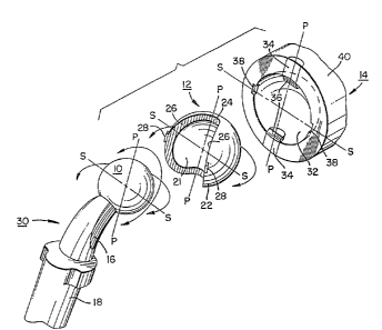
Figure 1 an assembly 20 of ball or sphere 10, socket
bearing 12 and cup 14 ~or a prosthetic joint. The neck
16 of arm 30 is intermediate ball 10 and stem or shaft
1~, which stem or shaft is fixed to, for example, the
femur bone at the time of implant surgery.
Figure 2 shows in more detail socket bearing 12 of
assembly 20. The preferred material for bearing 12 is
ultra-high molecular weight polyethylene (UHMWPE). Inner
spherical bearing surface 21 of bearing 12 is concentric
with outer s~herical bearing surface 22. Cylindrical
surfaces 24 are coaxial with each other and with the
center o~ spherical surfaces 21 and 22 and are tangent to
surfaces 26. Small barb-shaped protuberances 28 serve a
detent function described below.
In the plane passing through the lines P-P in Figure
2, socket bearing 12 encompasses less than one half of
ball 10. In the plane passing through the lines S-S, the
socket bearing encompasses more than half of ball 10.
Owing to the resilience and elasticity of the
plastic material of socket bearing 12, socket bearing 12
can be snapped over ball 10. The amount of interference
between the equator of the ball and socket bearing 12
depends on the angular extent of the bearing's opening in
the plane passing through the lines S-S in Figure 2. The
amount of interference should be such as will cause an
elastic deformation of socket bearing 12 while the
bearing is being assembled over the ball 10. To aid in
assembly, socket bearing 1~ can be heated to a
non-destructive temperature (for example 70-80C for
UHMWPE). Plastic in general, and UHMWPE in particular,
has a large coefficient of thermal expansion and such
thermal expansion due to heating significantly aids in
assembly.
50~L
-18-
As sho~l in Figure 2, cup 1~ has a hemispherical
inner surface 32 and two coaxial stub half pin members 34
which are structurally integral with cup 1~. The pins 34
are shown beveled at 36~ Recesses 38 are provided at the
inner rim o~ ~he cup at locations 9~ displaced from the
pins 3~. The exterior sur~ace 40 of cup 1~ is of any
conventional contour for fixation in bone whether by use
of cement, or without cement by means of impaction,
screwing in, or by bone ingrowth into porous metal or the
like. Cup 14 is normally made of metal, and it is to be
understood that the metal used is to be structurally and
biologically suitable for surgical implantation.
A step midway in the process of assembly is
schematically shown in Figure 3 where bearing 12 has been
positioned against neck 16 at 42 and the bearing 12 and
arm 30 have been inserted into cup 14 with neck 16
contacting the rim of cup 14 at 4~. Cylindrical surface
2~ of bearing 12 engages stub pin 34 as the entering rim
46 of bearing 12 contacts inner surface 32 of cup 14. At
this time the bearing 12 is pressed firmly enough into
cup 14 to compress protuberance 28, allowing bearing 12
to be rotated clockwise about ball 10 and pin 34 while it
is in contact with inner spherical surface 32.
W~len bearing 12 has been rotated sufficiently for
protuberance 28 adjacent rim 46 to reach recess 38,
protuberance 28 expands to resis~ rotation in the reverse
direction and thereby resist disassembly of the ball and
socket joint 20 unless a tool is inserted into recess 38
to again compress protuberance 28 as rotation in the
disassembly direction is started.
The assembled joint is shown in Figure 1, where the
neck 16 of arm 30 can move through the arc from the
position shown to that which is symmetrically opposite.
That is, the neck of the prosthesis can move in the plane
through lines P-P of Figure 2 from a position of contact
with lower stub pin 3~ to contact with upper stub pin 34.
When ball 10 has a diameter of 28mm and the outer
19-
diameter of bearing 12 i5 42mm, the arc or range of
motion of neck 16 is somewhat greater than 135D,
depending on the design of the neck 16.
To achieve this same range o~ motion in the plane
through lines S-S in Figure 2 requires two motions.
First, as shown in Figure 4, the neck 16 and ball 10 move
through the angle A by the ball 10 turning inside the
socket bearing 12, at the completion of which neck 16
contacts the rim of bearing 12. Thereafter, as shown in
Figure 5, to achieve the full range of motion A', ball 10
and bearing 12 rotate in unison, at the completion of
which neck 16 contacts cup 14.
Normally, until neck 16 reaches the rim of socket
bearing 12, socket bearing 12 will remain stationary
relative to cup 14. This is so because frictional torque
is the product of friction force times the distance from
the center of rotation. Given similar materials, finish
and geometric accuracy, so that the coefficient of
friction for ball 10 and cup 14 against bearing 12 are
equal, the frictional force on inner surface 21 will be
the same as that on outer surface 22 when ball 10 rotates
within cup 14, because the load transmitted across the
two bearing surfaces is the same. Since the radius to
the outer surEace 22 is the greater, the frictional
torque at the outer surface will be the greater and thus
motion will occur along surface 21 rather than surface
22.
For major oscillation of ball 10 and neck 16 in the
plane through lines P-P in Figure 2, the entire excursion
is due to rotation of ball 10 within bearing 12. The
total possible oscillation in all planes is the same,
however, the contribution made by rotation of bearing 12
increases as the plane of oscillation moves from that
including the lines P-P to that including the lines S-S
in Figure 2.
As described above, bearing 12 constrains ball 10
from dislocation. Further, soc~et bearing 12 is
-20- 5 ~
constrained within cup 14 by cylindrical surEaces 24 being
journaled by the stub half pins 34 in all positions oE
bearing 12 as bearing 12 moves to allow arm 30 to move
through angle A'. In -the complete assembly 20, -the
cons-traint against dislocation of ball 10 by deformation
of plas-tic bearing 12 is great~r in magnitude than the
force required to assemble bearing 12 over ball 10
because, in addi-tion to the fact that the assembly
operates at the body temperature of 37~C, the bearing
12 is now itself constrained against the deflection of
dislocation by being captured within metal cup 14.
Figures 6, 7 and 8 show an alternate construction
intended to (1) facilitate final assembly at the operative
site, and (2) for hip ~oint replacements, allow the axis
of stub pins 34 to be inclined accordingly to the
anatomical requirements of the patient as determined by
the surgeon. Cup 14 now includes two portions -- portion
64 which is affixed in the patient's bone, and retaining
ring portion 74 which carries stub pins 34 and is
engageable with portion 64 at a number of locations to
provide a plurality of orientations for the axis through
pins 34 about which socket bearing 12 rota-tes. Portion
6~ is shaped to accept and hold retaining ring 74 by means
of bayonet spaces 68 and lugs 70. Inner spherical surface
72 is continuous with spherical surface 76 oE ring 74.
Ring 74 carries stub half pin members 34, has recesses
38 and bayonet lugs 78. A particularly preferred
construction for portion 64, and, in particular, for the
exterior surface of this portion, is disclosed in U.S.
Patent 4,662,891 to Douglas G. Noiles on May 5, 1987,
and assigned to the assignee of the present application.
With the embodiment shown in Figures 6-8, the portion
64 of cup 14 is implanted in the patient's bone by, for
example, conventional techni~ues or, most preferably,
by the techniques described in the above-referenced pa-tent
to Douglas C. Noiles.
~2~5~1
Ball 10 and bearing 12 are assembled into retaining ring
74 after stem 18 of arm 30 has been implanted in, for
example, the patient's femur, the assembly procedure
being the same as that described above with reference
to Figure 3 except that protuberance 28 ls compressed
only once it contacts the back surface of ring 74. The
sub-assembly of ball 10, bearing 12 and retaining ring
74 is then inserted into portion 64 in any of the several
angular positions the bayonet lug fittings will permit.
A fraction of a turn in either direction will engage
the lugs 78 of ring 74 under lugs 70 of portion 64.
Alternatively, lugs 78 can be beveled a-t either their
right or left hand leading edges so that insertion by
rotation in only one direction is facilitated, e.g.,
clockwise rotation. The engagement of bayonet lugs 78
and 70 is locked by conventional means, such as by one
or more pins 80. Holes 79 and 81 for such locking pins
can be precisely made in the cooperating parts at the
time of manufacture. Although only one hole 81 is shown
in Figures 6 and 7, a hole would normally be drilled
at each bayonet space 68 so -that ring 74 can be locked
in place for any of its possible orientations.
An embodiment of the present invention similar to
that shown in Figures 6-8 but employing the system
disclosed in the aforementioned DeCarlo U.S. Patent
4,524,467 is shown in Figures 15-20. In this embodiment,
spherical surface 72 has associated therewith pin or
projection 50. This projection is located at the
geome-tric pole of the spherical cavity formed by spherical
surfaces 72 and 76. As shown in the figures, pin 50
has sloping sides 60.
Projection 50, in combination with aperture 13 formed
in outer surface 22 of bearing member 12, serves to
constrain the rotation of bearing 12 so as to prevent
the bearing from being rotated out of the spherical
SO~
-22-
cavity once the joint is assembled and to limit the
rotation of the bearing so as to keep neck 16 just out of
contact with the rim of ring 74, e.g., on the order of a
half a millimeter above the rim. In particular, bearing
12 can rotate only to the point where polar pin 50 and
one of the end walls 52 or 54 of aperture 13 are in
engagement. As discussed below, this constrained
condition for bearing 12 occurs automatically as the
joint is assembled without any additional assembly steps.
Also, the constraining of socket bearing 12 within the
joint is accomplished irrespective of the angular
orientation chosen for retaining ring 74 with respect to
body portion 64 of cup 14.
Aperture 13 has a long axis parallel to side walls
58 and 58 and a short axis at 90 to side walls 56 and
58. The angular extent of aperture 13 along its short
axis is sufficient to accommodate polar pin 50. The
angular extent of aperture 13 along its long axis
determines the range of motion of socket bearing 12. As
discussed above, a particularly preferred range motion
for bearing 12 is one in which neck 16 is kept just out
of contact with ring 74. In this case, as shown in
Figures 19-20, the angular extent (~) of aperture 13
along its long axis is determined by~ the maximum
angular extent (~) of socket bearing 12; 2) the minimum
angular extent (y) of cup 14; 3) the angular extent (~)
of polar pin 50; and the angular offset ( E ) of neck 16
from cup 14. In particular, the angular extent of
aperture 13 is given by:
~ y _ ~
Similar relations can be derived for other desired
ranges of motion for socket bearing 12.
The placement of pin 50 at the pole of the spherical
cavity formed by surfaces 72 and 76 allows retaining ring
74 to be inserted into body portion 64 of cup 14 in any
of the possible orientations provided by the mating of
.,
bayonet lugs 78 with bayonet lugs 70. That is J once
~6~
-23-
soclcet bearing 12 is rotated about stub pins 34 until
at least some portion of aperture 13 is located over the
central axis oE ring 74, ring 74 can be mated with body
portion 64 in any of their possible relative orientations,
because, for each of -those orientations, aperture 13 will
slip over projection 50. Since placing aperture 13 abou-t
pin 50 resul-ts in the restraining of bearing 12 in cup
14 without any further action by the surgeon, it can be
seen that assembly of the joint automatically produces
the desired restraining function.
A typical sequence oE steps for implanting the
prosthesis of the embodiment shown in Figures 15-20 in
a patient are as follows. Stem 18 of arm 30 is implanted
by conventional techniques in, for example, the patient's
femur bone. Body portion 64 of cup 14 can also be
implanted by conventional techni~ues or, most preferably,
by the techniques described in the above-referenced U.S.
Patent 4,662,891 to Douglas G. Noiles. Bearing 12 is
assembled into ring 74 and then ball 10 is forced into
bearing 12. Alternatively, bearing 12 can first be placed
on ball 10 and that combination assembled into ring 74.
In either case, the sub-assembly of ball 10, bearing 12
and retaining ring 74 is then inserted into body portion
64 in any of the several angular positions the bayonet
lug Eittings will permit, with polar pin 50 sliding into
aperture 13. A fraction of a turn in either direction
will engage the lugs 78 of ring 74 under lugs 70 of
portion 64. Alternatively, as discussed above, lugs 78
can be beveled at either their right or left hand leading
edges so that insertion by rotation in only one direction
is facilitated, e.g., clockwise rotation. To aid in the
rotation of ring 74, the ring can include apertures 122
for engagement with a spanner wrench or the like. Note
that because of the polar location of pin 50, ring 74
and its attached bearing 12 can be rotated to engage lugs
78 and 70 irrespective of where pin 50 is located along the
~ 2 ~ ~ 5
-24-
length of aperture 13. The engagement of bayonet lugs 78
and 70 is locked by one or more screws 83 which pass
through openings 100 and 98 in lugs 70 and 78,
respectively, and then through holes 102 to engage the
bone into which cup 64 has been implanted.
For hip joints, the possibility of a number of
orientations for the axis of rotation of bearing 12 is
used to place that axis in an orientation in which the
greater required range of motion is aligned approximately
with axis P-P. For example, the axis of rotation can be
oriented upward in the forward direction to achieve this
result. In this way, almost all of the highly repetitive
load bearing motions of the joint will occur along or
close to this axis. As discussed above, motions along or
near to the axis of rotation of bearing 12 consist
primarily of ball 10 moving in bearing 12~ rather than
bearing 12 moving in cup 14. As also discussed above,
the frictional torques involved further favor movement of
ball 10 in bearing 12. Accordingly, by placing the axis
of rotation of bearing 12 in a favorable orientation,
most repetitive motion will occur by movement of ball 10.
This is an important advan~age because it means that the
joint will have low friction in that friction increases
with the diameter of the moving member and ball 10 has a
smaller diameter than bearing 12. Put another way, by
orienting the axis of rotation of the bearing 12 in the
manner described above, the joint of the present
invention for the great majority of motions of the
patient's limb exhibits the frictional behavior of a
small ball, e.g., a 28mm ball, while providing a range of
motion corresponding to a large ball, e.g., a 42mm ball.
Figures 9 and 10 show another embodiment employing
retaining ring 74 in which the socket bearing comprises
two metal half bearings 82. A groove 86 is formed along
the junction of the bearings and ends short of the edge
of the bearing to form shoulders 88. Me-tal half bearings
82 are brought together to encompass ball 10, and the
~L2~4S0~
-25-
ball, half bearings, retaining ring 74 and portion 64 of
cup 14 are assembled in the same manner as described
above in connection with Figures 6-8.
Screws 94 having screw heads 96 are conveniently
used both to lock lugs 70 and 78 in place and to prevent
socket bearing 12 from rotating back out of retaining
ring 74. Screw heads 96 ride in groove 86 and engage
shoulders 88 when socket bearing 12 has been moved
through its full range of motion about stub pins 34.
Lugs 70 and 78 have appropriate openings 100 and 98,
respectively, ~o receive screws 94 and allow the screws
to be engaged with, in this case, threaded screw holes
102. Although only two openings 100 and two threaded
screw holes 102 are shown in Figures 9 and 10, such
openings and threaded holes would normally be provided at
each lug 70 so that ring 74 can be locked in place for
any of its possible orientations.
As shown in Figures 9 and 10, and most clearly in
Figure 10, screw heads 96 for the present embodiment lie
above the plane of the front face of retaining ring 74.
So as to provide the same range of motion of socket
bearing 12 for this embodiment as for the embodiment of
Figures 6-8, stub pins 34 also lie above this plane, so
that the axis of rotation of socket bearing 12 is in the
plane of screw heads 96. For this arrangement, the
motion of bearing 12, and thus arm 30, is limited by
screw head 96 contacting shoulder ~8, rather than by neck
1~ contacting retaining ring 74.
A further embodiment of the present invention is
shown in Figures 11 and 12. This embodiment employs
means other than half stub pins 34 to define the axis of
rotation of socket bearing 12 within cup 14. In
particular, a dovetail arrangement is used wherein male
portion 90 of the dovetail is attached to socket bearing
12 and female portion 92 of the dovetail is cut into
surface 32 of cup 14. Socket bearing 12 and cup 14 are
assembled in a manner similar to that shown in Figure 3.
~2~i~S~)l
-26-
That is, after socket bearing 12 has been placed over
ball 10, the ball and socket bearing are moved into cup
14 until the center of ball 10 lies at the center of the
cup's spherical cavity. Thereafter, socket bearing 12 is
rotated so that n~ale portion 90 and female portion 92 of
the dovetail engage with each other. To retain socket
bearlng 12 within cup 14, screws 94 can be inserted into
threaded holes 104 in cup 14 so as to block the outward
passage of male portion 90 of the dovetail from cup 14.
Figures 13 and 14 show alternate socket bearings for
use with the present invention.
In Figure 13, cylindrical surfaces 2~ do not ex~end
completely through the wall of bearing 12, but rather
stop approximately half way through to leave webs 106.
So as to provide as large a range of motion of arm 30 in
the plane through lines P-P as possible (see Fig~re 2),
the webs extend to just above height of stub pins 34 at
the end of bevels 36. In this way, as discussed above,
the motion of ball 10 in the plane through lines P-P is
limited by arm 16 contacting webs 106. The webs,
although small, help restrain ball 10 within bearing 12.
Figures 14 and 21-23 show embodiments of bearing 12
which do not physically constrain ball 10. For these
embodiments, inner surface 21 of bearing 12 has a
cylindrical shape 108 beyond its equator. This provides
a semi-constrained type of construction having a greater
depth than presently available. Such a bearing can be
used with the other components of the present invention
to provide the advantages, discussed above, of (1)
producing a wider range of motion, e.g., on the order of
135, and (2) providing a level of friction
characteristic of a small ball for the majority of the
motions of the patient's limb.
Figures 24 25 show another embodiment of the present
invention wherein a plastic bearing 12 is fitted at its
rim 118 with a metal reinforcing band 120 to produce a
constrained joint able to withstand higher dislocation
s~
-27-
forces than, ~or example, the joints including plastic
bearings shown in Figures 1 8 and 15 20. For this joint,
the order of assembly is first to combine bearing 12 with
ring 74, then to force the bearing 12 over ball 10 and
finally to assemble band 120 to the rlm of bearing 12.
If tlle ball portion of the joint has already been
implanted in the patient, this assembly order means that
band 120 has to be places over ball lO before the bearing
is mounted onto the ball.
The constructions of Figures 6-8, 9-10~ 15-20, 21-23
and 24-25 illustrate various joint configurations which
can be interchangeably connected to body 64 by means of
bayonet lugs 70 and 78 on body 64 and ring 74,
respectively. These configurations share the common
characteristic that bearing 12 is free to rotate about
stub pins 34 in the final assembled joint. They differ
from one another in the degree of constraint imposed on
the ball by the bearing and/or the types of materials
used to construct the bearing. Because the bearings are
free to rotate, these joints, when applied to hip
reconstructions, also share the characteristic that there
is a preferred orientation of the joint with respect to
the patient's anatomy, namely, an orientation wherein
most of the highly repetitive load bearing motions of the
joint occur along or close to the axis of rotation of the
bearing.
Figures 26-34 show further examples of joint
components which can be interchangeably connected to body
64 by means of bayonet lugs 70 and 78 on body 64 and, in
this case, on bearing 12, respectively. These joint con-
figurations have the common characteris~ic that bearing
12 is stationary with respect to body 64. As with the
joints of the prior examples, these joints differ among
themselves in the degree of constraint imposed on the
ball by the bearing and/or the types of materials used to
. construct the bearing.
-28-
More particularly, Figures 26-30 show a construction
of the constrained type employing a plastic socket
bearing to which has been added a metal reinforcing band
120 at rim 118 of the bearing so as to increase the
bearing's ability to withstand dislocation forces. As
shown in the figures, the bearing includes a recess 126
at its pole which allows the bearing to be used with a
body 64 which includes a polar pin 50. Of course, if
body 64 does not have a polar pin, the bearing need not
have recess 126.
Assembly of a completed joint using this bearing is
accomplished as follows. First, bearing 12 i9 forced
over ball 10 and band 120 is forced over the bearing's
rim 118. If the ball portion of the joint has already
been implanted in the patient, band 120 must be placed
over ball 10 before the bearing is mounted onto the ball.
The sub-assembly of ball 10, bearing 12 and reinforcing
band 120 is then inserted into body 64 in any of the
several angular positions the bayonet lug fittings will
permit. Polar pin 50 is received in recess 126 during
this process. Slnce the bearing of Figures 26-30 is
symmetric and thus does not define a particular
orientation with respect to the patient's anatomy, the
specific orientation of the bearing with respect to body
64 is immaterial. Once placed into body 64, a fraction
of a turn in either direction will engage the lugs 78 on
the bearing under the lugs 70 of body 64. If desired, as
described above, lugs 78 can be beveled at either their
right or left hand leading edges so that insertion by
rotation in only one direction is facilitated, e.g.,
clockwise rotation. To aid in the rotation of bearing
12, the bearing can include slots 128 for engagement with
a spanner wrench or the like. The engagement of bayonet
lugs 78 and 70 is locked by one or more screws 83 which
pass through openings 100 and 98 in lugs 70 and 78,
respectively, and then through holes 102 in body 64 to
~c;450~
-29-
engage the bone in which cup 64 has been implanted (see
Figures 33 and 34).
Figure 31 shows another plastic socket bearing of
essentially the sam~ design as the bearing of Figures
26-30 except that rather than creating a constrained
joint, this bearing produces a semi-constrained joint.
That is, the bearing of Figure 31 does not encompass more
than one half of ball 10 and thus does not constrain the
ball withîn the joint. Assembly of a joint using this
bearing simply involves inserting and locking the bearing
in body 64 using bayonet lugs 78 and one or more bone
screws, and then placing ball 10 into bearing 12 using
the standard techniques employed in semi-constrained
surgical reconstructions.
Figure 32 shows another plastic socket for use in a
semi-constrained reconstruction, in this case with an
added lip 130 to help restrain dislocations of ball 10
from the bearing. The lip can be conveniently formed by
gradually sloping the front surface of the bearing as
shown in Figure 32. A suitable slope is OIl the order of
9. Unlike the symmetric bearings of Figures 26-31, the
bearing of Figure 32 does define an orientation between
itself and the patient's anatomy. Accordingly, when
installing this bearing, the surgeon will choose an
orientation of the bearing with respect to body 64 which
will place lip 130 in the most advantageous position to
inhibit dislocation. Other than this orientation step,
the installation procedure for a joint using this bearing
is identical to the installation procedure described
above for the bearing of Figure 31.
Figures 33-34 show a non-rotating, constrained joint
employing a metal bearing. The bearing is composed of
two half-bearings 132 which carry bayonet lugs 78.
During assembly of the joint, half-bearings 132 are
placed about ball 10 and then held in place by plastic
retaining ring 134. The sub-assembly of ball 10 and
4 5
30-
bearing 12 is then inserted into body 64 in basically the
same manner as the bearing of Figures 26-30.
Typically, body 6~ is made of a titanium alloy,
e.g., an alloy containing 6% aluminum and 4% vanadium
(see ASTM Spec. No. F136-79)~ while bearing halves 132,
as well as ball 10, are made of a cobalt-chromium alloy.
~s is known in the art, titanium alloys are not wear
resistant when in moving contact with cobalt-chromium
alloys and thus continual relative movement between a
titanium part and a cobalt-chromium part will eventually
result in significant wearing of the titanium part.
To prevent such wearing due to relative movement,
the joint of Figures 33-34 includes wedge 136 which
serves to force half-bearings 132 into tight engagement
with body 64. Wedge 136 passes through slot 140 in
bearing 12 and into recess 144 in retaining ring 134.
The head portion 148 of the wedge is struck with a hammer
or the like after bearing 12 has been positioned in body
64. The hammer blow forces the bearing halves apart and
locks them into position with respect to body 64.
To prevent wedge 136 from working loose over time,
bone screw 83 ~an be used to engage the head of the wedge
as shown in Figure 34. So that the wedge can easily be
removed, e.g., during replacement of the bearing by a
different type of bearing, the underside of head 148 can
be cambered so that the wedge can readily be pried away
from the bearing. Because the wedging process causes the
bearing halves 132 to move away from each other by
pivoting about their point of contact opposite the
location of the wedge, the interior surfaces of the
bearing halves can be contoured so that a spherical
surface is formed only after the outward movement of the
bearing halves. Alternatively, the interior surfaces can
be made spherical since the slight amount of play between
ball 10 and bearing 12 caused by the wedging process can
normally be tolerated in the completed joint.
As can be seen most clearly in Figure 33, edge 146
of bearing 12 is not symmetric. More partic~llarly, this
edge allows ball 10 to move through one angular range in
the plane of Figure 34 and a relatively larger angular
range in the plane orthogonal to the plane of Figure 34.
Accordingly, when installing this bearing, the surgeon
will choose an orientation of bearing 12 in body 64 which
causes the plane corresponding to the relatively larger
range of angular motion to coincide as closely as
possible with the plane in which the patient's limb
normally moves through its largest range of angular
motion.
The nine joint configurations shown in Figures 6-8,
9-10, 15-20, 21-23, 24-25, 26-30, 31, 32, and 33-34 are
each interchangeable with each other. This inter-
changeability gives the surgeon the flexibility of being
able to choose, in situ, any of these configurations or
any other con~iguration constructed to mate with body 64.
In this way, a more perfect match between the
requirements of the patient and the characteristics of
the artificial joint is achieved.
From the foregoing, it is evident that the present
invention provides a constrained ball and socket joint
which has a range of motion greater than that generally
available in artificial joints whether of the constrained
or semi-constrained type. Moreover, the present
invention provides an artificial joint which can be
oriented in the patient to provide low friction movement
of a ball of relatively small diameter for most of the
patient's repetitive activities. The limiting factor in
providing ~he increased range of motion is the outside
diameter of the bearing. Accordingly, within anatomical
limits, it is advantageous for the bearing outside
diameter to be as large as possible.
The increased range of motion provided by the
present invention allows the patient to move his limb
further than heretofore possible in constrained joints
-32-
without the arm of the prosthesis impinging on the edge
of the bearing. Accordingly, there is less likelihood of
dislocation when plastic bearings are used or disruption
of the bond between the fixation element and the bone to
S which it is attached when metal bearings are used.
Moreover, when the range of motion of the present joint
is greater than the patient can take advantage of, the
surgeon is afforded greater latitude for variation in the
orientation of the prosthetic components with respect to
1~ the patient's anatomy without the hazard of impingement.
In addition to these orientability and range of
motion aspects, the present invention, by providing
interchangeable sockets, also gives the surgeon the
ability to select the most appropriate prosthesis for the
patient's specific requirements both during the initial
operation and, if necessary, during re-operations. As
demonstrated by the examples described abo~e, the
surgeon, in accordance with the present invention, has a
diverse family of ball and socket joints to choose rom
extending from semi-constrained, fixed bearings made of
plastic through constrained, rotating bearings made of
metal, as well as a variety of configurations in between.
This choice plainly permits a better match between the
requirements of the patient and the capabilities of the
prosthesis.
Numerous modi~ications and variations of the present
invention are possible in light of the above teachings.
For example, ball 10, socket bearing 12 and retaining
ring 74 can be provided to the surgeon as a unit, rather
than being assembled at the surgical site. Also, metal
socket bearings can be used with one piece cups, such as
cup 14 shown in Figure 1, rather than with a retaining
ring as shown in Figures 9 and lO. Furthermore, various
connecting means other than bayonet spaces and lugs can
be used to attach ring 74 or bearing 12 to body 64, such
as, snap rings. In addition, a variety of socket
bearings other than those specifically illustrated herein
-33-
can be used to make up the family of interchangeable
bearings supplied to the surgeon. It is therefore
understood that within the scope of the appended claims,
th~ invention may be practiced otherwise than as
specifically described.