Note: Descriptions are shown in the official language in which they were submitted.
6~58~
--1--
The present invention is a division of the canadian
patent application 442,243 filed on November 30, 1983.
The present invention relates to a photoradiator
for effectively radiating light propagating therethrough
in a desired direction and in a desired quantity to the
ambience, while furnishing it with an optical property
suitable for a desired application.
Effective use of solar energy is tne key to energy saving
today and has been studied in various fields actively.
For the most effective use of solar energy, solar energy
has to be availed as it is without being transformed
into another kind of energy such as thermal energy or
electrical energy. In light of this, I have made
various proposals for an illumination system which
utilizes solar energy. The illumination system employs
a light conducting element such as a fiber optic cable
through which the sunlight converged by a lens or the
like is conducted to a desired location to stream out
thereat to illuminate the ambience.
In the illumination system of tne type described,
the light advancing through the light conductor has
directivity. Therefore, if the light is output at a
simple cut end of the light conductor, it becomes
radiated over an angle ~ which is usually as small as
about 46. The light streaming through the simple cut
end of the light conductor would fail to evenly
ill~minate a desired space such as a room. I have
proposed in various forms a photoradiator which is
designed to effectively diffuse ligh~ conducted by a
J~
~64S83
- 2-
fiber optic cable to provide even illumination over a
wide range.
Another problem encountered with a light conducting
element of the kind described is that when it is laid
over a len~th sufficient for practical use, fringes
develop in the light emanating from the light conductor
which are undesirable for ordinary lighting applieations~
although some particular applications may rather prefer
them. '~hexe the light propagating through the light
~uide is a laser or ~he like~ fringes appear therein
even if the light eonductor is of a very small diameter
such as an optieal fiber, rendering the light unfeasible
or use with a laser microscope or the like.
SUMMARY OF THE INVENTION
It is therefore an objeet of the present invention
to provide a photoradiator whieh is capable of effeetive-
ly diffusing light transmitted therethrough to the
outside by means of a simple construetion.
Z0 It is another objeet of the present invention
to provide a photoradiator whieh allows light propagat-
ing therethrough to be radiated to the outside in a
desixed direction and in a desired quantity.
It is another object of the present invention to
provide a photoradiator which radiates light having a
desired optical property.
It is another object of the present invention to
provide a generally improved photoradiator.
According to the present invention there is provided
a serially arranged cylindrical light conducting rods for
propagating light along the axial length of the cylin-
drical light conducting rods and for reflecting the light
laterally outwardly, comprising first and second cylin-
drical light conducting rods each having a longitudinal
~Zf~aS83
~ - 3 -
axis and each having an outer cylindrical wall, the first
cylindrical llght conducting rod having a first longitudinal
end section, the second cylindrical light conducting rod
having a second longitudinal end section, the first
longitudinal end section having two i.nner diverginy flat
walls and an inner flat end wall, the inner flat end wall
having two sides and two ends, the two inner diverging flat
walls each having an outer terminating end extending to the
longitudinal end of the -first longitudinal end section, the
two diverging walls diverging as the longitudinal end of the
first longitudinal end section is approached, the second
longitudinal end section having two outer converging flat
walls and an outer flat end wall, the outer flat end wall
having two sides and two ends, the two outer converging flat
walls each having an outer terminating end which is
coincident with the sides of the outer flat end wall, each
of the two outer converging flat walls extending to the
longitudinal end of the second longitudinal end section, the
two converging flat walls each converging as the longitudi-
nal end of the second longitudinal end section is
approached, the first and second light conducting rods being
disposed in a serial and axially aligned position with the
two diverging inner flat walls along with the inner flat end
wall being complementarily arranged respectively with the
two converging outer flat walls along with the outer flat
end wall such that the complementarily disposition of the
two diverging inner flat walls with the converging outer
flat walls facilitates the axial alignment, whereby light
propagating through the first cylindrical light conducting
rod is transmitted to the second cylindrical light
conducting rod via the inner and outer flat end walls while
the rest of the light being prvpagated is partly reflected
laterally outwardly by the two diverging inner flat walls
and the two converging outer flat walls and. partly transmit-
~4S~3
~ 3a -
ted through the two diverging inner flat walls and the two
converging ou-ter flat walls into the second cylindrical
light conducting rod, the serially arranged conducting rods
thereby propagating the light axially and reflecting the
light laterally outwardly thereof.
The area of each of the two diverging flat walls
may be equal, or it may be different such that one of the
two diverging flat walls reflects more light laterally out-
wardly than the other diverging f]at wall.
The area of each of the two converging flat walls
may be equal, or it may be different such that one of the
two converging flat walls reflects more light laterally
outwardly than the other converging flat wall.
According to the present invention, there is also
provided a serially arranged cylindrical light conducting
rods for propagating light along the axial length of the
cylindrical light conducting rods and for reflecting the
light laterally outwardly, comprising first and second
cylindrical light conducting rods each having a longitudinal
axis and each having an outer cylindrical wall, the first
cylindrical light conducting rod having a first longitudinal
end section, the second cylindrical light conducting rod
having a second longitudinal end section, the first
longitudinal end section having two inner diverging flat
walls and an inner flat end wall, the inner flat end wall
having two sides and two ends, the two inner diverging flat
walls each having an outer terminating end extending to the
longitudinal end of the first longitudinal end section, the
two diverging walls diverging as the longitudinal end of the
first longitudinal end section is approached, the second
longitudinal end section having two outer converging Elat
walls and an outer flat end wall, the outer flat end wall
having two sides and two ends, the two outer converging flat
walls each having an outer terminating end which is coinci-
lZ6gL~33
~ - 3b -
dent with the sides of -the outer flat end wall, each of the
two outer converging flat walls extending to the longitudi-
nal end of the second longitudinal end section, the two
converging flat walls each converging as the longitudinal
end of the second longitudinal end section i5 approached,the
~irst and second light conducting rods being disposed in a
serial and axially aligned position with the two diverging
inner flat walls along with the inner flat end wall being
complementarily arranged and aligned respectively with the
two converging outer flat walls along with the outer flat
end wall and with an air space between the two diverging
inner flat walls and the two convergir,g outer flat walls,
whereby light propagating through the first cylindrical
light conducting rod is transmitted to the second
cylindrical light conducting rod via the inner and outer
flat end walls while the rest of the light being propagated
is partly reflected laterally outwardly by the two diverging
inner flat walls and the two converging outer flat walls via
the air space and partly transmitted through the two
diverging inner flat walls and the two converging outer flat
walls via the air space into the second cylindrical light
conducting rod, the serially arranged conducting rods
thereby propagating the light axially and reflecting the
light laterally outwardly thereof.
According to the present invention there is also
provided a serially arranged cylindrical light conducting
rods for propagating light along the axial length of the
cylindrical light conducting rods and fo.r reflecting the
light laterally outwardly, comprising first and second
cylindrical light conducting rods each having a longitudinal
axis and each having an outer cylindrical wall, the first
cylindrical light conducting rod having a first longitudinal
end section, the second cylindrical light conducting rod
having a second longitudinal end section, the first
~Z69LS83
~- 3c -
longitudinal end section having two inner diverging flat
walls and an inner flat end wall, the inner flat end wall
having two sides and two ends, the two inner diverging flat
walls each having an outer termina-ting end extending to the
longitudinal end of the first longitudinal end section, the
two diverging walls diverging as the longitudinal end of the
first longitudinal end section is approached, the second
longitudinal end section having two outer converging flat
walls and an outer flat end wall, the outer flat end wall
having two sides and two ends, the two outer converging flat
walls each having an outer terminating end which is
coincident with the sides of the outer flat end wall, each
of the two outer converging flat walls extending to the
longitudinal end of the second longitudinal end section, the
two converging flat walls each converging as the longitudi-
nal end of the second longitudinal end section is
approached, the first and second light conducting rods being
disposed in a serial and axially aligned position with the
two diverging inner flat walls along with the inner flat end
wall being complementarily arranged and aligned respectively
with the two converging outer flat walls along with the
outer flat end wall,a semitransparent layer disposed between
the two diverging inner flat walls and the two converging
outer flat walls, whereby light propagating through the
first cylindrical light conducting rod is transmitted to the
second cylindrical light conducting rod via the inner and
outer flat end walls while the rest of the light being
propagated is partly reflected laterally outwardly by the
two diverging inner flat walls and -the two converging outer
flat walls via the transparent layer and partly transmitted
through the two diverging inner flat wall and the two
converging outer flat walls via the transparent layer into
the second cylindrical light conducting rod, the serially
arranged conducting rods thereby propagating the light
~IL2~S83
3~ -
axially and reflecting the light laterally outwardly
thereof.
The above and other objects, features and
advantages of the present invention will become apparent
from the following detailed description taken with the
accompanying~drawings.
BRIEF DESCRIPTION OF THE DRAWINGS
Figures lA and lB to 4A and 4B are views of
various embodiments of a photoradiator in accordance with
the present invention, suffix "A" indicating a sectional
side elevation and suffix "B", a cross-section;
Figures 5-9 are views of other embodiments of the
present invention;
Figures 10-15 are perspective views of other
embodiments of the present invention;
Figure 16 is a perspective view of a modification
to a transparent control member included in the
photoradiator of Figure 15;
/
~264S83
Figure 17 is a side elevation of the control
member of Figure 16 which is positioned to reflect
incoming light;
Figures 18 and 19 are views of a prior art simple
cylindrical light conducting element; and
Figures 20A and 20B to 22A and 22B are views of
other embodiments of the present invention.
DESCRIPTIOl~ OF THE PREFERRED EMBODIMENTS
While the photoradiator of the present invention
is susceptible of numerous physica~ embodiments,
depending upon the environment and requirements of use,
substantial numbers of the herein shown and described
embodiments have been made, tested and used, and all
nave performed in an eminently satisfactory manner.
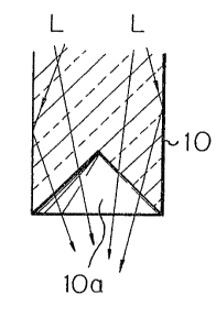
Referring to Figures lA and lB, a photoradiator
em~odying the present invention is snown and comprises
a light conducting element in the form of a rod 10. The
light conductor 10 optically connects at one end thereof
(not shown) to a source of converged light supply (not
shown). The other end of the light conductor L0 is
formed with a single conical notch lOa in order to
efectively diffuse light as will be described.
Light such as sunlight L is converged by a lens
or the like into the light conductor 10 at the source.
The light L propagates through the light conductor 10
while being repeatedly reflected by the rod wall. At
the notch lOa in the end of the rod 10, the light L
is partly transmitted through the conical surface to
the outside and partly reflected tnereby to change its
course before being radiated. Stated another way, the
light L propagating through the rod 10 is diffused to
the outside at the conical end lOa over a substantial
radiation angle.
A modification to the structure of Figures lA and
S83
and lB is shown in Figures 2A and 2B. As shown, the
light conducting element 10' is formed with a number of
conical notches lO'a at the light outlet end tnereof.
The effect attainable with such a multi-notch structure
is essentially common to that achieved with the single
notch s~ructure.
In both the structures shown in Figures lA and lB
and 2A and 2B, the conical notch configuration is only
illustrative and may be replaced by a polygonal pyramid
such as triangular pyramid or quadrangular pyramid.
If desixed, the notched surface or surfaces may be
finished for diffusion in order ~o effectively scatter
the light to make tne illumination tender to the eyes.
The principle described above is similarly
applicable t4 a light conducting element in the form
of a pipe. In Figures 3A and 3B, a light conducting
pipe 20 comprises an annular wall 22 the light outlet
end of which is cut aslant to define a radially outwardly
flared opening 20a. In Figures 4A an~ 4B, a light
conducting pipe 20' comprises an annular wall 22' the
light outlet end of which is formed with a number of
recesses or notches 20'a at spaced locations along the
circumference of the pipe.
In the photoradiator shown in Figures 3A and 3B
or 4A and 4~, the converged light L such as sunlight
propagates through the pipe wall 22 or 22' while being
repeatedly reflected by the other peripheral surface
thereof. The notch 20a or notches 20~a serve to
e~fectively diffuse the light L to thereby radiate it
to the ambience~
If desired, the embodiment shown in Figures 3A and
3B ana that shown in Figures 4A and 4B may be combined,
that is, the light outlet end of a light conducting
pipe may be cut to have a flared opening and formed
with a number of recesses along the circumference
lZ64583
--6--
thereof. Again, the light outlet end may be finished
to serve as a light scattering surface and the
illustrated notch configuration is only illustrative.
Referring to Figure 5, another ernbodiment of the
S present invention is shown which is applied to a light
conducting rod. The light conductor 30 in Figure 5
is formed with a plurality of spaced notches 30a along
the circumference thereof and in a selected position
between axially opposite ends. Part of light L
propagating through the rod 30 is partly diffused
radially outwardly by the walls of the notches 30a.
This type of circumferential notch arrangement is also
applicable to a light conducting pipe, as shown in
Figure 6. The pipe 32 in Figure 6 is formed with
notches 32a at spaced locations along the circumference
thereof and in a selected position between axially
oppoiste ends. The photoradiator in Figure 6 functions
in the same manner as the photoradiator shown in
Figure S, except that it reflects the light at both the
2~ inner and outer walls thereof.
In the photoradiator shown in Figure 5 or 6, a
lower end wall 30al or 32al of each notch may be
inclined radially outwardly with its associated upper
end wall 3a2 or 32a2 formed perpendicular to the
direction of light propagation as illustrated (to the
axis of the light conductor 30 or 32). Alternatively,
the upper end wall 3a2 or 32a2 may be oriented
substantially parallel to the inclined lower end wall,
as indicated by a phantom line in the drawing. Such
a set of notches may be located at a nurnber of spaced
locations along the direction of light propagation, or
the axis of the light conductor. In this case, the
radial depth d of the notches may be sequentially
increased in the direction of light propayation in
order to set up substantially uniform radiation of
~Z64583
--7--
lignt along the axis of the light conductor.
Referring to Figure 7, another embodiment of the
present invention is shown which has a plurality of
light conducting rods (34-38 in the drawing) interconnect~
ed end-to-end in the illustrated order a-ong the direction
of light propagation. As sho~n, the rod 36 is ormed
with notches 36a so that the inclined walls 36al thereof
may effectively diffuse light coming out from the
bottom of the rod 34. Likewise, the rod 38 below the
rod 36 is formed with notches 38a to diffuse li~ht at
the inclined walls 38al thereof. Such a serial inter-
connection scheme is applicable to light conducting
pipes as well. As shown in Fig~re 8, pipes 40-44 are
interconnected sequentially along the direction of
light propagation. The pipe 42 has notches 42a with
inclined walls 42a1 and the pipe 44, notches 44a with
inclined walls 44al.
It will be seen that the diffusion of light
attainable with the photoradiator shown in Figure 7
or 8 is as effective as that attainable with the photo-
radiator of Figure 5 or 6. NeVertheless, the photo-
radiator of Figure 7 or ~ is distinguishable over the
photoradiator of Figure 5 or 6 by the easier and more
accurate production due to the serial connection
of a plurality of light conducting elements which
have been individually machined to have the notches.
A modification to the photoradiator of Figure 8
is illustrated in Figure 9~ As shown, the pipe 40 is
connected to the pipe 42 by a light conducting rod 46
whose refractive index is larger than that of the
pipe 40. Likewise, the pipe 42 is connected to the
pipe 44 by another light conducting rod 46. The
photoradiator ha~ing such a construction attains
efficient transmission of light, since the light
transmitted through the bore of any pipe is introduced
~26~5~3
into the annular wall of the adjacent pipe by the rod
46; the pipe walls have a higher light transmission
efficiency than air.
Referring to Figures 10-13, other embodiments of
the present invention are shown which are commonly
designed to diffuse light raidally outwardly to the
ambience. In Figure 10, the photoradiator comprises
light conducting elements 50 and 52 which are connected
end-to-end to each other. The end of the element 50
adjacent to the other element 52 comprises a flat surface
50a, while the end of the element 52 comprises a
frustoconical inclined surface 52a which terminates at
a flat top 52b. When the light conductors 50 and 52 are
assembled together, light propagating through the light
conductor S0 will be partly introduced into the follow-
ing light conductor 52 and the rest is diffused
effectively to the outside by refelection at the
inclined surface 5Za while being partly routed into the
element 52.
In the photoradiator shown in Figure 10, the
inclination angle 0 of the inclinecl surface 52a is
variable to steer the light in a desired direction out
of the photoradiator. Where the angle ~ is 45 degrees,
for example, the light will be radiated perpendicular
to the axis of the pilotoradiator if it is parallellight, and over a substantial radiation angle if it is
converged light. Also, the ratio in area between the
inclined surface 52a and the flat top 52b may be
varied to set up any desired ratio between the quantity
of light steered to the outside and the quantity of
light transmitted to the subsequent light conductor.
In Figure 11, a light conducting element 50'
is formed with a frustoconical recess 50'a and a flat
surface 50'b which are generally complementary to the
contiguous frustoconical surface 52a and flat surface
~Z6~S~3
_9_
52b of the light condueting element 52, whieh is the
same as the element 52 of Figure 10. In this construe-
tion, light propagating through the element 50' is
partly transmitted to the element 52 via the aligned
flat surfaees 50'b and 52b, while tne rest is partly
refeleeted outwardly by the inclined surfaces 50'a and
52b and partly transmitted into the element 22. The
photoradiator eonstruction shown in Figure 11 is
advantageous in that i~ allows the two elements 50' and
52 to be aligned with ease to eaeh other.
In Figure 11, should the interconneeting surfaees
of the rods 50' and 52 be eonfigured fully eomplementary
to eaeh other, no light would be refelected by the
inelined surfaees. It is preferable, therefore, to
desposite a semitransparent layer on the inclined
surfaee of either one of the rods 50' and 52. Generally,
however, it will suffiee to form them approximately
complementary so that an air spaee may be defined
therebetween to refleet part of the propagatins light
at the inelined surfaees.
In Figure 13, the photoradiator comprises a
eylindrieal light eondueting element 54 having a flat
end 54a, and a light eondueting elemeht 56 having two
inelined surfaees 56a and 56b whieh eonverge to a
flat top 56e. In this ease, light transmitted through
the light conductor 54 will be diffused outwardly in
two directions by the inclined surfaces 56a and 56b.
Again, the light eonductor 54 may have its end formed
complementary to that of the light conductor 56 as shown
in Figure 13. In Figure 13, the element 54' has a recess
defined by opposite inelined surfaces 54'a and 54'b
and a flat surface 54'c. The construction shown in
~igure 13, like that shown in Figure 11, will promote
easy alignment between the two coaetive light conductors
54' and 56.
~Z~5~
-10-
While in the embodiment shown in Figure 12 or 13
the opposite inclined surfaces 56a and 56b are assumed
to be equal in area to each other, they may be provided
with different areas such that a larger quantity of
light is reflected by one of them than by the other.
In the extreme case, the configuration may be such that
the light is reflected by one inclined surface 60a of
a light conducting element 60 as indicated by an arrow
A. In this case, light may be supplied from the light
conductor 60 into an upper light conductor 58 as
indicated by an arrow ~.
Referring to Figure lS, another embodiment of the
present invention is shown which is furnished with means
for controlling a quantity of light radiation. The
photoradiator in Figure 15 comprises a first light
conducting element 62, a second light conducting element
64 and a transparent control member 68. Either one
of the elements 62 and 64 (64 in this particular
e~bodiment) is formed with a recess 64a at an end
thereof which connects to the other element. The
transparent control member 68 is removably disposed in
the recess 64a. As shown, the control member 64
includes a flat surface 68a and an inclined surface 68b.
In this photoradiator construction, light propagating
through the light conductox 62 is partly transmitted
to the light conductor 64 via the flat surface 68a of
the control member 68 and the rest is partly reflected
outwardly by the inclined surface 68b while being
partly routed into the light conductor 64.
A characteristic feature of the photoradiator
shown in Figure 15 is that the quantity of light steered
by the inclined surface 68b of tne control member 68
is adjustable by controlling the position of the
control member 68 in the recess 64a. Light from the
li~ht conductor 62 will be partly reflected by the
~LZ64S~33
inclined surface 68b of the control member 68 as
indicated by an arrow A, while light from the light
conductor 64 will be reflected by the inclined surface
86b as indicated by an arrow B. Therefore, light may
be supplied in either one of the opposite directions
as desired.
Another example of the transparent control member is
shown in Figure 16. As shown, the alternative
transparent control member 70 comprises two inclined
surfaces 70al and 7a2 which reflect light from the
light conductor 62 (Figure 15) in two different
directions, as indicated by arrows A. The position of
such a control member is adjustable in the recess 64a
(Figure 15) to vary the pro~ortions of the light
reflected by the opposite inclined surfaces 70al and
70a2 to each other. Again, only one inclined surface
may be formed on the member 70 in the extreme case.
The control member 70, different from the control
me~ber 68 of Figure 15, is incapable of reflecting
light coming in from the light conductor 64 (Figure lS),
since it would reflect it back thereinto at the inclined
surfaces 70al and 7a2 as indicated by arrows ~.
It will be apparent that a number of interconnec-
tion surfaces each including an inclined surace or
surfaces as described may be defined sequentially along
the axis of the photoradiator. In such a case, the
control member 70 shown in Figure 16 may be installed
in the photoradiator in the position shown in Figure 17
to return light reached the last light conductor n,
thereby causing more effective radiation of light.
It is necessary then to treat a flat surface 70b
between the inclined surfaces 70al and 7a2 to reflect
incident light.
Now, assume a simple cylindrical light conducting
element 80 as shown in Figures 18 and 19. When parallel
~;4S~3
--12--
light Ll is introduced into one end A of the light
conductor 80 as shown in Figure 18, it will be radiated
from the other end B without any divergenee. When the
incident light is converged light as indicated by L2
5 in Figure lg, it will be radiated over a divergence
angle a of about 46 degrees. However, sueh a simple
eylindrieal light eonduetor suffers from the drawbacks
previously discussed. Farther embodiments of the
present invention will be deseribe whieh are elaborated
10 to radiate light after varying its optieal property
to suit a desired applieation.
~ eferring to Figures 20A and 20Bt the photoradiator
~omprises a light eondueting element 90 whieh is made
up of a eylindrieal portion 90a and a frustoconieal
lS portion- 90b whieh -extends tapered from the eylindrieal
portion 90a. When eonverged light L2 is ineident on an
end A of the eylindrieal portion 90a, it will propagate
through the light eonduetor 90 while being refleeted
by the wall of the eontinuous portions 9Oa and 9Ob.
20 The light output from an end B of the frustoeonieal
portion 90b has a substantial divergenee angle due to
the N.A whieh has increased during tl~e travel of the
light through the frustoeonieal portion 90b. Fringes
whieh develop in the light output from the photo-
25 radiator 90 will be feasible to speeial decorativeapplications. For more general lighting applications,
parallel light Ll may be introdueed into the light
conductor 90 as shown in Figure 20B. The light outgoing
the light conduetor shown in Figure 20B is substantially
30 identical in optieal property with the incoming light.
Referring to Figure 21A, the photoradiator
comprises a light condueting element 92 having a
cylindrical portion 92a and a frustoconical portion
92b, and a second light eonducting element 94 having a
35 cylindrical portion 94a and a frustoconical portion 94b.
~Z~;4583
-13-
The light conductors 92 and 94 are interconnected at
the ends of their frustoconical portions 92b and 94b
as illustrated. This type of co~struction eliminates
fringes in the light radiated from the photoradiator,
since the fringes developed in the light conductor 92 is
cancelled in the second light conductor 94. If desired,
use may be made of a single piece light conductor 96
as shown in Figure 21B, which is identical in configura-
tion with the interconnected light conductors 92 and
94.
Another embodiment of the present invention is
shown in Figure 22A which comprises a light conducting
element g8 having a cylindrical portion 98a and a
frustoconical portion 9~b contiguous with the cylindrical
portion 98a, and a second light conducting element 100
having a frustoconical portion lOOa, a cylindrical
portion lOOb and a frustoconical portion lOOc~ This is
similar to the construction shown in Figure 21A except
for the additional conical portion lOOc which, as in the
construction of Figure 20A, serves to increase the
radiation angle of output light by reflection. Again,
the two light conductors 93 and 100 may be replaced
with a single light conductor 102 configured generally
identical thereto.
Various modifications will become possible for
those skilled in the art after receiving the teachings
of the present disclosure without departing from the
scope thereof.