Note: Descriptions are shown in the official language in which they were submitted.
FLUIDIZED 6ED COMBUSTOR
HAYING INTEGRAL SOLIDS SEPARATOR
BACKGROUND OF THE INVENTION
The present invention relates to fluidized bed
combustors wherein a particulate fuel is combusted in a
fluidized state, and, more-particularly, to such a combustor
having an integral solids separator for removing particulate
material carried over in the flue gas generated in the
combustion chamber.
In a typical present day fluidized bed combustor,
particulate fuel; such as coal having a top size ranging up to
about 6.5 millimeters, is typically fed to and combusted within
a furnace chamber in a fluidized state in a fluidizing gas at
relatively low temperatures ranging from about 760 C. to 925 C.
Fluidized bed furnaces are particularly adaptable to burning
sulfur containing fuels as the particulate material fluidized
wi~hin the furnace may include a sulfur absorbent, most
commonly crushed limestone, in addition to the particulate
fuel. Fluidizing air, which also serves as combustion air, is
supplied to the furnace from an air plenum located beneath the
combustion chamber. In a typical circulating fluidized bed,
also referred to as a fast fluid ked bed, the velocity or flow
rate of the fluidizing air being passed upwardly into the
furnace is maintained at a level sufficiently high to entrain
most of the particulate material present wi~hin the furnace
such that a substantial portion of the particulate material
with;n the combustion chamber is carried therefrom with the
flue gas.
C850820
... , .~."
.
. . . .
.: ' ' . ; ; '
Accordingly, it is necessary on circulating or fast
fluidized bed combustors to provide a means for removing the
particulate material carried over from the combustion chamber
with the flue gas prior to venting the flue gas to the
atmosphere. As this particulate material typically contains a
significant amount of unburned fuel, it is further advantageous
to collect the particulate material from the gas stream for
recycle to the combustion chamber of the furnace for further
combustion in order to increase the efficiency of fuel
1~ utilization. Additionally, the particulate material removed
from the gas stream will generally contain a significant amount
of unreacted sulfur absorbent which is also recirculated to the
combustion chamber of the furnace in order to increase the
efficiency of util;zation of the sulfur absorbent.
The most common means for separating tha particulate
solids from the flue gas passing from the combustion chamber
prior to venting same to the atmosphere is a cyclone separator.
A circulating fluidized bed system utilizing a cyclone for a
particulate collection is illustrated in U.S. Patent 4,lll,158.
As shown, the cyclone is typically installed immediately
downstream of the furnace in order to facilitate recycle of the
collected particulate material to the furnace. As the
particulate solids entrained in the flue gas will have a
temperature reflecting the temperature of the flue gas, the
cyclone separator will be exposed to both hot solids and hot
gases and therefore must be designed to withstand temperatures
ranging as high as 1600 C. under normal operation.
Additionally, the cyclone separator must be designed to survive
operation in a highly erosive environment as the particulate
loading in the flue gas will result in a significant impact of
erosive particles on the side walls of the cyclone.
Accordingly, the type of cyclone suitable for utilization in a
circulating fluidized bed system has a high capital cost and
frequently a high operating cost associated therewith.
It would be desirable to substitute a less Pxpensive
separating means for the cyclone on a typical circulating
C850820
.. .
.:" ,. ..
3L2 ~ 3
-3-
fluidized bed furnace. Examples of such circulating fluidized
bed furnace systems utilizing non-cyclonic separators are
illustrated in U.S. Patents 4,442,797 and 4,538,549 which show,
respectively, the use of momentum separators and the use of
impact separators for removing particulate material from the
flue gas passing from the combustion chamber.
In U.S. Patent 4,442,797, the flue gas passing from
the furnace chamber to the flue gas vent duct must exit the
furnace chamber through a plurality of vertical slot-like
openings formed by bending the waterwall tubes in the upper
wall of the combustion chamber inwardly from the plane of the
wall to provide a flow area betwee~ adjacent tubes. A plenum
chamber extends in belt-like fashion around the upper region of
the furnace chamber to receive the flue gas which passes
through these tubes. As the flue gas passes through the
slot-like openings formed between tubes, the flue gas drops in
velocity below the ~ntrainment level and the particles carried
therein drop out of the flue gas stream and are directed to a
collection hopper for recycle to the furnace chamber.
In U.S. Patent 4,538,549, impact beams are provided
at and immediately downstream of the gas outlet of the furnace
chamber. The flue gas leaving the combustion chamber of the
furnace passes between the rows of impact beams while the
particulate solids contained therein, due to their flow
inertia, strike the impact beams. As a consequence of striking
the impact beams, the particles lose their momentum and drop
out of the gas stream into a collection hopper for recycle to
the furnace while the flue gas passes on to the vent stack.
It is an object of the present invention to provide a
fluidized bed combustor having an integral non-cyclonic solids
separator for removing the hot particulate solids carried in a
flue gas stream prior to venting the ~lue ~as stream to the
atmosphere.
SUMMARY OF THE INVENTION
A circulating fluidized bed combustor system for
burning a particulate fuel in a fluidized state in a fluidizing
C850~320
.
' ', "'.~'`: '
,. .. .
~2~
-4-
gas comprising a furnace enclosure defining a combustion
chamber having a hot gas outlet, a flue gas duct disposed
downstream of the furnace enclosure for venting the flue gas
generated in the combustion chamber, separator means integrally
incorporated into the gas flow path downstream of the furnace
chamber and upstream of the flue gas duct for separating
particulate solids carried over from the furnace chamber in the
Flue gas, and solids collection means for receiving particulate
solids from the separator means.
The separator means comprises an arcuate duct having
an inlet opening to the gas outlet of the furnace enclosure for
receiving the hot flue gas from the chamber and an outlet
spàced from the inlet. The arcuate duct comprises spaced
curvilinear inner and outer walls extending from the inlet of
the duct to the outlet of the duct, and a pair of spaced
s;dewalls extending transversely between the spaced inner and
outer walls. A portion of the curvilinear inner wall of the
arcuate duct comprising separator means is disposed across the
flue gas duct inlet and has a plurality of openings formed
therein for providing a flow area thro~gh which a first major
portion of the hot flue gas passes from the arcuate duct of the
separator means into the flue gas duct for venting to the
atmosphere. A second minor portion of the flue gas passes
throuyh the outlet of the arcuate duct into the solid
collection means and carries with it the particulate solids
separated from the first portion of the flue gas passing
through the inner wall of the arcuate duct of the separator
means. Due to the curvilinear shape of the arcuate duct,
centrifugal forces are generated which act on the particles
passing through the separator means so as to cause the
particles within the flue gas passing therethrough to
concentrate along the curvilinear outer wall of the arcuate
duct.
The particulate solids contained in the first portion
of the f1ue gas passing through the openings in the inner wall
of the arcuate duct have sufficient momentum so that they do
C850820
~ ... . .
: , ....
.
not follow the path of the first portion of the FIue yas through
the openings in the inner wall of the arcuate duct, but rather
pass to the outlet of the arcuate duct and are carried in a
second minor portion of the flue gas along the outer
S curvilinear wall of the arcuate duct through the outlet into
the solids collection means.
Preferably, the portion of the inner curvilinear wall
of the arcuate duct of the separator means disposed across the
inlet to the flue gas duct comprises a plurality of spaced
louvers disposed transversely between the spaced sidewalls of
the arcuate duct so as to provide a plurality of openings
therebetween. Each of the louvers is disposed at an acute
angle with the local tangent to the curvilinear inner wall
whereby the first portion of the ~lue gas which passes through
the openings therein must sharply change its direction of flow,
while the solid particles, being under the influence of much
higher inertia forces, separate from the first portion of flue
gas as it changes direction of flow to pass through the openings
between the louvers, and continue along the curvilinear flow
path through the arcuate duct to be concentrated by centrifugal
forces in a second minor portion of the flue gas which passes
along the outer curvilinear wall of the arcuate duct to the
solid collection means disposed at the outlet of the arcuate
duct.
BRIEF DESCRIPTION OF THE DRA~ING
The features and advantages and objects of the
present invention will be evident from the following
description of the illustrated embodiments thereof in the
accompanying drawing wherein:
Figure 1 is a side elevational view illustrating a
fluidized bed combustor incorporating an integral non-cyclonic
solids separator in accordance with the present invention;
Figure 2 is a side elevational view of an alternate
embodiment of a fluidized bed boiler system incorporating a
non-cyclonic solids separator in accordance with the present
invention;
C850820
.. . . . . .
..
., ,." .
- . ~ ~ ' ~ .' ' . '
..
-6-
Figure 3 is a side elevational view of an alternate
embodiment of a Fluidized bed boiler system incorporating a
non-cyclonic solids separator in accordance with the present
invention;
Figure 4 is a cross-sectional plan view taken along
line 4-4 of Figure l;
Figure 5 is a sectional elevation view taken along
line 5-5 of Figure 1;
Figure 6 is a enlarged sectional elevational view
showing a curvilinear floor portion of the solid separator
wherein the floor portion is formed of a plurality of louvers;
and
Figure 7 is a cross-sectional view taken along line
7-7 of Figure 6.
DESCRIPTION OF A PREFERRED EM~ODIMENT
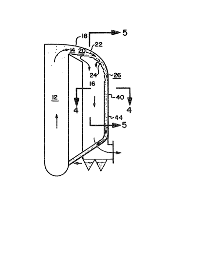
Referring now to the drawings, there is depicted
therein a fluidized bed furnace lO wherein a sulfur containing
fuel, such as particulate coal, is combusted in a fluidized
state with additional particulate material which includes a
sulfur oxide absorbent. The particulate fuel is combusted in
the fluidizing air within the combustion chamber 12 defined by
the furnace enclosure lO to generate a hot flu~ gas which exits
the combustion chamber 12 through the furnace gas outlet l4.
The hot flue gas leaving the combustion chamber l2 through the
furnace gas outlet 14 is passed to the flue gas vent duct l6
for venting to the atmosphere. Typically, convection surface,
not shown, is disposed in the flue gas vent duct l6 to cool the
gas prior to venting the flue gas to the atmosphere through a
stack, not shown.
As the particulate fuel in a circulating or fast
fluid bed is combusted in a fluidized state in a fluidizing gas
having a velocity sufficient to not only fluidize but also
entrain a substantial portion of the particulate material
present within the combustion chamber l2, the particulate
material entrained in the flue gas leaving the combustion
chamber 12 through the gas outlet l4 must be removed from the
C850820
- . . ;
. .. .
.
. .. - . . ..
.
. ..
,
. ... .
2 ~ 3
-7-
flue gas stream prior to venting ~he flue gas stream to the
atmosphere. In typical prior art circulating fluidized bed
furnace systems, a cyclone separator was typically disposed
downstream of the furnace gas outlet 14 intermedia~e the
combustion chamber and the flue gas vent duct to remove a major
portion of the particulate material for recycle to the furnace
chamber. The flue g2s passing through the flue gas vent duct
16 would still contain some particulate material which would be
typ;cally removed from the flue gas stream by passing the flue
gas stream through a fabric filter type collector prior to
venting the flue gas through the stack. As noted previously,
it would be advantageous to eliminate the cyclone separator in
favor of a much simpler and lower capital cost separation
means.
In accordance with the present invention, the means
18 for separating the particulate solids carried over from the
combustion chamber in the flue gas passing through the furnace
gas outlet 14 comprises an integral part of the furnace system
in the form of an arcuate duct ~0 having an inlet opening to
the gas nutlet 1~ of the furnace enclosure 10 for receiving the
hot flue gas from the combustion chamber 12. The arcuate duct
20 is formed of a curvilinear outer wall 22, a curvilinear
inner wall 24, and a pair of spaced sidewalls extending
transversely therebetween. It is to be understood that "inner
wall" refers to the curvilinear wall of the arcuate duct having
the lesser radius of curvature, while "outer wall" refers to
the curvilinear wall of the arcuate duct having the greater
radius of curvature. In the embodiment shown in Figure 1, the
furnace gas outlet 14 of the furnace 10 is in a vertical plane
and the arcuate duct 20 of the separator means of the present
invention comprises a downwardly curved duct subtending an
angle of 90 degrees between a vertically disposed inlet mating
with the furnace gas outlet 14 and a horizontally disposed
solids outlet 26. In the embodiment shown in Figure 2, the
furnace gas outlet 14 is in a horizontal plane and the arcuate
duct 20 of the separator means of the present invention
C850820
.
.. : ~ .. . . ..
-8-
comprises a semi-torodial duct subtending an angle of 180
degrees between a horizontally disposed inlet mating with the
furnace gas outlet 14 and a horizontally disposed solids outlet
26 spaced therefrom at the opposite end of the duct. In the
embodiment shown in Figure 3, the furnace gas outlet 14 is in a
horizontal plane and the arcuate duct 20 of the separator means
of the present invention comprises a downwardly curved duct
subtending an angle of 90 degrees between a horizontally
disposed inlet mating with the furnace gas outlet 14 and a
ln vertically disposed solids outlet 26.
A portion of the curvilinear inner wall 2~ of the
arcuate duct 20 is disposed across the inlet to the flue gas
duct 16 and has a plurality of openings 28 therein which
provide a flow area through which a first portion of the hot
flue gases pass from the arcuate duct 20 of the separator means
to the flue gas duct 16. Gas-solids separation is accomplished
in the separator means of the present invention as the flue gas
turns sharply from its arcuate path through the duct 20 to pass
through the openings 28 in the curvilinear inner wall 24 of the
duct. Due to the centrifugal forces exerted on the particulate
solids in the flue gas as it passes through the arcuate duct
20, the particulate solids have sufficient momentum that they
continue along their arcuate path through the duct 20 and are
unable to follow the flue gas as it turns sharply from its
arcuate flow path to pass through the holes 28 in the
curYilinear inner wall of the duct 20. The flue gas having
passed through the curvilinear inner wall 24 of the arcuate
duct 20 enters the flue gas vent duct 1~ at a significantly
reduced solids content. This reduced solids content flue gas
3~ continues through the flue gas vent duct 18 over convective
cooling surface disposed therein and is, if necessary, passed
therefrom to a fabric filter or multiclone mechanical separator
for further removal of particulate material prior to venting to
the atmosphere through a stack, not shown.
The substantial portion o~ solid particulate material
in the hot flue gas passing from the furnace chamber through
C850820
~' . ~.'.
' ' - ,. ~, '.; ' ` ' ~ ',
.
-9-
the furnace gas outlet 14 passes through the solids outle-t 26
of the arcuate duct 20 into solids collection means 40 which
opens to the solids outlet 26 of the arcuate duct 20 at the end
o~ the arcuate duct opposite from the inlet thereto. These
solids are concentrated and entrained in a second minor portion
of the flue gas passing through the arcuate duct 20 and are
carried through the solid collection means 40 and recycled back
to the combustion chamber 12 within the furnace enclosure 10.
It is necessary and advantageous to recycle this particulate
material as it will contain unburned particulate fuel and also
unutilized particulate sulfur absorbent.
Solids separation is also enhanced in accordance with
Applicants' invention in that the separator means is in the
form of an arcuate duct having a curvilinear outer wall. As a
result of this duct configuration, the solids within the flue
gas passing from the furnace gas outlet 14 are drawn by
centrifugal forces to concentrate in the flue gas passing along
the outer wall of the arcuate duct 14 and away from the portion
of the flue gas which will pass along and through the inner
wall of the arcuate duct 20.
As best seen in Figures 4 and 5, the solids outlet 26
of the arcuate duct 20 opens at the base of the curvilinear
outer wall 22 to the solids collection means 40 which
preferàbly comprises a receiviny hopper 42 and a plurality of
downcomer conduits 44 which extend downwardly from the
receiving hopper 42 and thence interconnect with the furnace
enclosure 10 to open to the combustion chamber 12 thereby
providing a flow path through which the particulate solids
entrained in the second minor portion of the flue gas passing
through the arcuate duct 20 are reinjected into the furnace
chamber. As the particulate solids and flue gas passing
through the downcomer conduits 44 will be at a high temperature
since they have not traversed any cooling surface in that they
have bypassed the flue gas vent duct 16, it is desirable to
provide internal or external cooling means operatively
associated with one or more of the downcomer conduits 44, such
C850820
.
,:, . .. . :, . . :
'
~z~
-10-
as t~e internally disposed cooling coil 46 illustrated in
Figure 3, so as to cool the solids prior to reinjection intc
the furnace chamber and take advantage of the heat content
contained therein to heat a liquid or a vapor for useful
purposes.
In the preferred embodiment of the present invention,
the portion of the curvilinear inner ~Jall 24 of the arcuate
duct 20 disposed across the inlet to the flue gas duct 16 is
formed of a plurality of spaced louver vanes 30 disposed
lQ transversely between the spaced sidewalls of the arcuate duct
20 so as to provide a plurality of openings therebetween. The
louvers 30 are disposed so as to extend at an acute angle to
the local tangent to the curvilinear inner wall so that the
flue gas passing through the arcuate duct along a path
substantially parallel to the curvilinear inner wall 24 of the
arcuate duct 20 must turn sharply back upon itself to pass
through the openings between adjacent louver vanes 30. As
mentioned previously, the solid particles in the flue gas are,
due to their momentum, unable to traverse the sharp turn
traversed by the flue gas passing through the curvilinear inner
wall and instead pass onwardly through the arcuate duct 20 to
the solids outlet 26 thereof.
It is also preferred that the cross-sectional area of
the arcuate duct 20 continuously decrease in flow area in the
direction of flue gas flow at least through that portion of the
duct bounded by the perforated portion of the curvilinear inner
wall 24 disposed atop the flue gas duct 16. If the cross-
sectional area of the duct 20 remained constant, the velocity
of the flue gas passing therethrou~h would decrease as a first
portion of the flue gas passes through the perforated floor in
the flue gas duct. As a consequence, the momentum of the
particulate solids in concentrating in second portion of the
flue gas would decrease as the velocity of the flue gas
decreases resulting in the potential for premature
precipitation of the particulate solids within the arcuate duct
20. This result is avoided by continuously decreasing the
cross-sectional area of the arcuate duct 20 as the first
C850820
~ ..... . .
- - . . .:, .: .. ,
'
~ ;, . ' ' ' ~
:
, ' :. : ' "
: ', ,,.` . . ~':,. ' '
-11-
portion of the flue gas vents through the perforated inner wall
24 into the flue gas duct 16 such that the velocity of the
second portion of the flue gas remains high enough to maintain
the par-ticulate solids therein in an entrained state so as to
carry the solids into the solids collection means 40.
Although the louver vanes 30 may take many forms of
construction, in the presently preferred embodiment, as best
seen in Figures 6 and 7, the individual louver vanes 30 are
mounted to curvilinear fluid cooled tubes 32 at an acute angle
with the curvilinear tube 32 to form the portion of the
curvilinear inner wall 24 which is disposed atop the flue gas
duct 16. rurther, as shown in Figure 6, each louver vane 30
may be formed of a plurality of segments 34 disposed in side by
side relationship across the inner curvature of the arcuate
duct ~0 with each individual segment mounted to a fluid cooled
tube 32 as opposed to being a single integral louver vane
extending across the inner wall 24 of the duct 20. The louver
vanes 30 may be made of ceramic or metal as appropriate for
- each given installation.
A particular advantage of the louver ~ane wall design
of Applicants' invention is that the louver vanes 30 are
disposed at a fairly small arcuate angle with the gas flow such
that the surface of the vanes will not be exposed to significant
erosive impact from particulate solids in the flue gas passing
through the curvilinear duct. Impact type separators used in
the prior art are necessarily exposed to high erosion as the
particles themselves impinge directly upon the separator in
order to slow their momentum so that they will separate from
the gas stream. Also, in prior art cyclonic type separators,
the whirling flow of particulate solids within the separator
creates high erosion of the walls of the cyclone separator.
The separator means of the present invention is not subject to
the highly erosive effects of the particles as the particles do
not directly impact upon the surface but rather flow along a
curvilinear path through the arcuate duct of Applicants'
separator. Applicants' separator depends upon the centrifugal
C850820
. :
:: ::
-12-
momentum of the particles generated when the flue gas passes
from the furnace outlet through the arcuate duct and upon the
perforated curvilinear inner wall requires the flue gas to
sharply turn in order to pass through the openings in the inner
wall which results in the solids to inherently separate from
the flue gas.
C850820
,
.. ~ .
. : : . ~::