Note: Descriptions are shown in the official language in which they were submitted.
~2~
63198-1020
Background of Invention
The apparatus and method of the present invention
relates generally to the separation, weighing, and
selecting a combination of weighed groups of elongated
articles to form a batch of articles of predetermined
weight, followed by the alignment of the articles in such
batch and packaging of such batch of aligned articles. In
particular, the invention is related to such an apparatus
and method in which successive batches of elongated
articles are aligned by different alignment systems
mounted on a common rotating support~ Each alignment
system includes a plurality of vibrating conveyor stages
which prealign the articles with their axes parallel to
the direction of travel before feeding them into an
- alignment container. The batch of articles are compacted
and further aligned in the alignment container ~ith their
longitudinal axis substantialy parallel, before the
aligned batch of articles is discharged from such
container into a packaginy machine where such batch is
packaged without disturbing such alignment. The apparatus
and method of the present invention is especially useful
in producing weighed batches of aligned elongated food
products, such as french fry potato strips.
Previously it has been proposed in U.S. Patent
4,398,612 of Mikami et al issued August 16, 1983 entitled
JC:sl 28470 1/27/86 4005H
"Automatic Weighing Apparatus" to provide a separator and
scale apparatus for separating a plurality of articles
into groups of articles which are fed into scale buckets
for weighing such groups. The weighed groups of articles
are automatically selectively combined by discharging some
of such groups from the scale buckets into a common
container chute to provide a batch of articles of
predetermined weight in such chute which is discharged
into a packaging machlne. However~ unlike the present
invention, there is no alignment system for aligning
elongated articles in the weighed batch of articles in the
manner of the present invention.
Similar separator and scale apparatus is shown in
U.S. Patent 4,465,150 of Matsumoto, issued August 14, lg34
and U.S~ Patent 4,467,880 of Minamida et al, issued August
28, 1984, which are both assigned to the same assignee as
the previously mentioned Mikami et al patent. This prior
art apparatus employs a computer for selecting those
weighed groups of articles which are combined to form a
batch of predetermined weight by selectively discharging
the scale buckets using computer generated gate signals as
shown in U.S. Patent 4,398,612 cited above.
Summary of Invention
It is therefore one object of the present
invention to provide an improved apparatus and method for
produciny weighed batches of aligned elongated articles in
a fast and efficient manner.
Another object of the invention is to provide
3~ such an apparatus and method with a high capacity
alignment mechanism including a plurality of alignment
,,
JC:sl 28470 1/27/85 4005H ~ 697
systems moun~ed on a common rotating support for
selectively positioning the input stage of each alignment
system beneath the output of a common collector container
supplying the weighed batches.
A further object of the invention is to provide
such an apparatus and method in which the alignment
systems each have an alignment container for aligning and
compacting the elongated articles into a weighed and
aligned batch of articles which is discharged from the
la alignment container into a packaging machine for packaging
without disturbing such alignment in order to provide a
compact package of aligned articles which occupy less
space during shipping and storage.
An additional object of the invention is to
provide such an apparatus and method in which the batches
of predetermined weight are produced in an accurate and
efficient manner by selectively discharging different
combinations of scale buckets containing weighed groups of
such articles into a common container to provide a batch
~a of articles of a predetermined weight automatically.
Still another object of the invention is to
provide such an apparatus and method in which each of the
alignment systems each include a plurality of vibrating
conveyor stages by which the elongated articles are
prealigned with their longitudinal axes substantially
parallel to their direction of travel before they are fed
into the alignment container.
A still ~urther object of the present invention
is to provide such an apparatus and method in which the
batch of~aligned articles is transferred from a vibrating
~6~7 6319~-1020
alignment container through a ~ransfer tube to the bagging
machine without jamming by providing a flexible mounted
connector tube between the bottom of the alignment container and
the transfer tube.
There is provided in accordance with the in~ention
apparatus for producing predetermined weighed batches of
elongated articles and for aligning the articles in batches,
comprising: separator means for separating a plurality of
elongated articles into groups of articles; scale means for
weighing each of the groups of articles; selection means for
selecting a combination of certain ones of said weighed groups
to provide a combination of selected groups whose total weight
is approximately equal to a predetermined weight, and for
discharging the selected groups into a common container to form
a batch of the articles, the batch being of the predetermined
weight; alignment means for aligning the articles in the weighed
batch in an alignment container so that the longitudinal axes of
the aligned articles are substantially parallel, the alignment
means including a plurality of alignment systems each having an
alignment container and including gate means for feeding the
weighed batches from the common container to different ones of
the alignment systems; and diæcharge mean~ for discharging the
aligned articles in a batch from the alignment container.
There is further provided a method for producing
predetermined weighed batches of elongated articles and for
aligning the article in the batches, comprising: separating a
plurality of elongated articles into groups of article~;
weighing each oP the groups of articles; selecting a combination
oP certain ones of the weighed groups to provide a combination
3~ of selected groups who~e total weight i~ approximately equal to
a predetermined weight; discharging the se.lected groups into a
--4--
6~'~
63198-1020
common container to form a ba~ch of the articles, the batch
being of the predetermined weight; and aligning the articles in
the weighed batch so that the longitudinal axes of the aligned
articles are substantially parallel, by conveying the weighed
batch of articles on a vibrating conveyor into an alignment
container.
Description of Drawings
Other objects and advantages of the present invention
will be apparent from the following detailed description of a
preferred embodiment thereof, and from the attached drawings of
which:
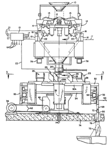
Figure 1 is a front view of the preferred embodiment
of the apparatus of the present invention;
Figure 2 is an enlarged side elevation view taken
along the line 2-2 of Figure l;
Figure 3 is a horizontal section view taken along the
line 3-3 of Figure 1 showing a plurality of alignment systems
mounted on a common rotating support beneath the outlet of the
common batch container of Figure 2;
Figure 4 is an enlarged horizontal section view taken
along the line 4-4 of Figure 3;
Figure 5 is an enlarged view of one of the alignment
systems of Figure 3; and
Figure 6 is an enlarged view of the output end of the
alignment system of Figure 5 showing discharge of an aligned
elongated article into the alignment container.
Detailed Description of Preferred Embodiment
As shown in Figure 1, a preferred embodiment of the
apparatus and method of the present invention includes a supply
hopper 10 containing a ~upply of the elongated articles, such as
french fry potato stripq, or other elongated food products. The
articles are discharged from
-4a-
. `
.,
.'
t
JC:sl 28470 1/27/86 4005H
the supply hopper 10 onto the upper surface of a separator
cone 12 which is vibrated by a vibrating mechanism 13 in
the manner described in U.S. Patent 4,39~,612 cited
above. Upon separation by the separator cone, the
articles are fed into ten separator containers 14 through
associated transfer feeders 15 to form groups of articles
in such separator containersO The transfer feeders 15 are
also vibrated in the manner described in such patent for
conveying such articles~ The groups of articles in the
1~ separator containers 14 are dumped into ten different
weighing containers or scale buckets 16 which are each
associated with ten different electronic weighing scales
18 spaced radially outward therefrom. The electronic
scales 18 each produce electrical signal corresponding to
the weight of the group of articles in the bucket 16 and
transmit such weight signal to an input terminal 17 of a
computer 19. Computer 19 may be a digital microprocessor
which processes the weight signals to produce gate control
signals on outputs 21 for selectively discharging the
~ buckets 16 into a common collector container 20 beneath
such buckets. Thus, the dump gates 22 at the bottom ends
of the scale buckets 16 are selectively opened by the gate
control signals on computer outputs 21 in order to
selectively discharge the groups of articles in such
buckets in different combinations of weights which will
total a predetermined weight to provide the batch of
articles in the common collector container 20 in the
manner of U.S. Patent 4,398,612 cited abo~e.
A batch gate 24 at the bottom of the common
collector container 20 is opened by a batch output signal
~z~
631g8-1020
on a computer output 23 to discharge the batch o~ articles into
one of eight alignment sygtems 25. Each of the alignment
systems includes three vibration conveyor stages including an
input conveyor stage 26, an intermediate conveyor stage 28 and
an output conveyor stage 30. During movement along the
vibrating conveyor stages, the elongated articles are prealigned
~ith their longitudinal axes substantially parallel to their
direction of travel along such conveyor stages. Each of these
conveyor stages is a vibrating conveyor of the type shown in
United States Patent 4,51~,959. The output conveyor stage 30
discharges the articles after they are prealigned by such
conveyor stages into an alignment container 32, in a manner
hereafter described with respect to Figures 5 and 6.
As shown in Figures 2 and 3, the eight conveyor
systems 25 are mounted on a common support frame 34 which is
rotated about an axis of rotation 36 by an electric drive motor
38 connected to a gear train 40 by a coupling chain or belt 42.
As a result, the support frame 34 and the alignmen$ systems 25
mounted thereon rotate in the clockwise direction of arrow 44 in
~0 Figure 3 about the axis of rotation 36 with an intermittent
motion. As a result, the input stage 26A of one selected
alignment system is positioned beneath the batch gate 24 of the
collector container 20 in the load position. After the weighed
batch of articles is dumped from the collector container 20 onto
the input stage 26 of the first conveyor system, the support
frame 34 and such conveyor systems are rotated ~5 degrees about
the axis of rotation 36 until the input
-- 6 --
,
JC:sl 28470 1/27/86 4005~
stage of a second alignment system is positioned under the
batch gate 24 for discharge of another batch onto the
second system. The first alignment system is rotated a
total of 360 degrees while it vibrates the articles on the
conveyor stages 26, 28 and 30 and feeds such articles into
the alignment container 32, until the alignment container
of such first alignment system is in the unload position
32A shown in Fig. 3. At this time the aligned articles
are discharged as a batch from such alignment container
into the bag machine, as hereafter discussed with respect
to Fig. 4.
The elongated articles are transported from the
input conveyor atage 26A through the intermediate conveyor
stage 28A, and the output conveyor stage 30A by vibration
causing such elongated articles to be prealigned with
their longitudinal axis substantially parallel to their
direction of travel when they reach the end of the output
conveyor stage. The prealigned articles are discharged
into the alignment container 32 by the time such alignment
~1~ system has rotated 360 about axis 36. It should be noted
that the frame 36 is provided with 45 degree intermittent
rotation so that each input conveyor stage 26 of the eight
conveyor systems is momentarily stopped in the load
position 26A of Fig. 3 for loading of the batches.
Similarly, such 45 degree intermittent rotation allows the
aligned articles in the alignment container 32 of each
alignment system to be discharged as an aligned batch into
the bagging machine at the unload position 32A of Figr 3.
As shown in Fig. 4, the alignment container 32 is
supported by top and bottom mounting backets 46 and 48 on
.
63198-1020
JC:sl 28470 1/27/86 4005~
spring shock mounts 50 and 52 fastened to a vibrator
member 54 which is vibrated by a vibration motor 56
coupled thereto. As a result, the alignment container 32
is vibrated to further compact and align the elongated
articles after they are dropped from the end of output
conveyor stage 30 into the top of such alignment
container. A discharge gate closes the bottom of the
alignment container including a pair of gate doors 58
pivotally mounted to the bottom ends of the alignment
la container at pivots 60. The gate doors 58 are opened by a
cylinder 62 controlled by an unload signal produced by the
computer 19 of Fig. 1 at an unload output 64. The weighed
and aligned batch of articles is discharged from the
alignement container 32A through the discharge gate 58
into a transfer tube 66, which is coupled by a connector
tube 68 to the bottom of such alignment container. The
transfer tube is attached to the connector tube by a
flexible coupling 70, such as a rubber strip mount, which
enables vibration of the connector tube 68 due to contact
~ith the vibrating alignment container while maintaining
such connector tube 6~ connected to the transfer tube
during discharge.
As shown in Fig. 1, a packaging mechanism having
an input chamber 72 is provided in alignment with the
transfer tube 66 for packaging the weighed aligned batch
of elongated articles when-they are transferred as a batch
from the alignment container through the transfer tube
into such packaging mechanism without disturbing their
alignment. One suitable packaging mechanism is shown in
~a United States Patent 4,514,959. The packaging
'~
'~6~
63198-1020
mechanism 72 may be mounted beneath a base support deck 74
supporting the frame 34 ~or the rotating alignment systems. In
this case, the transfer tube 66 extends through a passageway 76
in such deck as shown in Figure 1. I~ should be noted that the
scale and separator mechanism are mounted on a pair o~ support
beams 78 above the support deck 74 with the batch gate 24 at the
bottom of the collector container 20 in alignment with the input
conveyor stage in load position ?6A, which is displaced from the
axis of rotation 36 of the alignment mechanism ~rame 34, as
shown in Figures 2 and 3.
As shown in Figures 5 and 6~ the alignment conveyor
stages 26, 28 and 30 are vibrating conveyors of the type shown
in United States Patent 4,514,959 which prealign the elongated
axticles 80 so that their longitudinal axes 88 are substantially
parallel to their direction of travel 82 on the output conveyor
stage 30. The output conveyor stage 30 is provided with a
plurality of longitudinal partitions 84 which divide the output
conveyor into a pluxality of parallel channels each having a
width ~' which is less than the length Y of the elongated
~n article, as shown in Figure 6. The output conveyor stage 30
terminates above the top of the alignment container 32 at the
front edge of such alignment container, so that the elongated
articles 80 traveling in the direction 82 parallel to partitions
84 strike the rear wall 86 of such container at an acute angle
of about 45 degrees, as shown in Figure 6. The width Z o~ the
container 32 is equal to X sine e where X is the distance from
the front edge to the rear wall 86 o~ such container along the
'J
JC:sl 28470 1/27/86 4005H
direction 82. The distance X is less than one-half the
length Y of the elonga~ed artic]e. As a resul~, the
elongated article 80 does not fall into the container
until its front end strikes the rear wall 86 of the
container.
Since the elongated articles 80 are prealigned
with their longitudinal axes 88 parallel to their travel
direction 82, such articles strike the rear wall 86 at
angle 0 and slide along the wall into the dashed line
position 80' of Fig. 6 until more than half the length of
such article lies over the opening of the alignment
container. Then the articles fall down into such
alignment container, since their center of gravity is over
the top opening of such alignment container. The
longitudinal axis 88' of the article 80 is thereby moved
into an aligned position generally parallel to the rear
wall 86 of the alignment container after such article
falls into such alignment container. In addition, due to
vihration of the alignment container 32 by the vibrator
~a motor 56, a more complete parallel alignment of the
longitudinal axis 88' of the articles within such
alignment container takes place as well as a compacting of
the articles. The result i5 that the articles are
discharged from the bottom of the alignment container as a
compact, aligned and weighed batch of articles to the
packaging mechanism 72 where such batch is packaged. This
is an improvement over conventional packaging of elongated
articles, such as french fry potatoes, with random
orientation to provide a larger package which requires
much more space during shipment and storage than the
-- 10 --
JC:sl 28470 1/27/86 4005H
packages of the aligned and weighed batches of articles
produced in accordance with the present invention.
It will be obvious to those having ordinary skill
in the art that many chan~es may be made in the above
described preferred embodiment of the present invention.
Therefore, the scope of the present invention should be
determined by the following claims.
~0