Language selection

Search

Patent 1264909 Summary

Third-party information liability

Some of the information on this Web page has been provided by external sources. The Government of Canada is not responsible for the accuracy, reliability or currency of the information supplied by external sources. Users wishing to rely upon this information should consult directly with the source of the information. Content provided by external sources is not subject to official languages, privacy and accessibility requirements.

Claims and Abstract availability

Any discrepancies in the text and image of the Claims and Abstract are due to differing posting times. Text of the Claims and Abstract are posted:

  • At the time the application is open to public inspection;
  • At the time of issue of the patent (grant).
(12) Patent: (11) CA 1264909
(21) Application Number: 519056
(54) English Title: INJECTION MOLDING MACHINE
(54) French Title: MACHINE DE MOULAGE PAR INJECTION
Status: Deemed expired
Bibliographic Data
(52) Canadian Patent Classification (CPC):
  • 18/703
(51) International Patent Classification (IPC):
  • B29C 45/20 (2006.01)
  • B29C 45/32 (2006.01)
(72) Inventors :
  • KAADEN, HANS-HEINRICH (Germany)
(73) Owners :
  • STUBBE GMBH (Germany)
(71) Applicants :
(74) Agent: SWABEY OGILVY RENAULT
(74) Associate agent:
(45) Issued: 1990-01-30
(22) Filed Date: 1986-09-25
Availability of licence: N/A
(25) Language of filing: English

Patent Cooperation Treaty (PCT): No

(30) Application Priority Data:
Application No. Country/Territory Date
P 35 34 255.2 Germany 1985-09-26

Abstracts

English Abstract


ABSTRACT OF THE DISCLOSURE


The invention relates to an injection molding machine for
the manufacture of plastic parts from thermoplastic, thermoset
and/or elastomer material by injection molding or reaction
injection molding. The machine includes a multi-station
locking unit of horizontal or vertical configuration designed
to hold a number of molds and an associated injection unit for
the simultaneous injection of the molds. The apparatus further
includes two outer mold clamping plates, one of which is
arranged on guide elements and movable thereon in the locking
direction, and a center mold-holding part movably arranged on
guide elements between the two mold clamping plates. The
mold-holding part is provided with a heatable melt conduction
system with sprue nozzles and has one half of a mold attached
to each of its two sides. The center mold-holding part is
designed as a mold clamping plate sectioned lengthwise in three
parts relative to the locking direction. The parts of the
sectioned mold clamping plate are kept together by a high-speed
clamping device and have the melt conduction system arranged
between the three parts so that it is possible to connect each
melt conduction system to an injection unit and inject the
associated mold separately or two different molds can be
injected simultaneously.
-7-


Claims

Note: Claims are shown in the official language in which they were submitted.


The embodiments of the invention in which an exclusive
property or privilege is claimed are defined as follows:

1. In an apparatus for the manufacture of
plastic parts from thermoplastic, thermoset and/or
elastomer material, said apparatus having a multi-
station locking unit adapted to hold a number of
molds, an associated injection unit for the
simultaneous injection of the molds, two outer mold
clamping plates, one plate of which is disposed on
guide elements and movable thereon in the locking
direction, a center mold-holding assembly movably
arranged in guide elements between the two mold
clamping plates, the center mold-holding assembly
being provided with a heatable melt conduction system
with sprue nozzles and having a section of a mold
attached to each of its two sides, the center mold-
holding assembly having a mold clamping plate having
the melt conduction system arranged therein and
separate driving cylinders being fastened on the mold
clamping plate, the improvement comprising:
the mold clamping plate being sectioned
crosswise to said locking direction into three parts
with said melt conduction system being arranged in
two parts between said three parts of said mold
clamping plate.

2. The apparatus according to claim 1, wherein
a separate injection unit is associated with each
part of the melt conduction system.

3. The apparatus according to claim 2, wherein
the mold clamping plate sectioned in three parts is
clamped together in a single unit by at least one
high-speed clamping device.


4. The apparatus according to claim 2,
wherein said melt conduction system is designed in
the form of melt conduction rails.


Description

Note: Descriptions are shown in the official language in which they were submitted.


~26490C~

The present invention relates to an
apparatus for the manufacture of plastic parts from
thermoplastic, thermoset and/or elastomer material by
injection molding or reaction injec-tion molding. The
5 apparatus includes a multi-station locking unit of
horizontal or vertical configuration designed to hold
a number of molds and an associated injection unit
for the simultaneous injection of the molds. The
apparatus further includes two outer mold clamping
plates, one of which is arranged on guide elements
and movable thereon in the locking direction, and a
center mold-holding part movably arranged on guide
elements between the two mold clamping plates. The
mold-holding part is provided with a heatable melt
conduction system with sprue nozzles and has one half
of a mold attached to each of its two sides. The
center mold-holding part is designed as a mold
clamping plate sectioned lengthwise relative to the
locking direction for holding larger halves of a
mold. The two parts of the sectioned mold clamping
plate are kept together by a high-speed clamping
device and have the melt conduction system arranged
therebetween. Separate driving cylinders are
fastened on the center mold clamping plate.
The injection molding machine described
above is disclosed in U.S. Patent 4,753,592, Kaaden,
June 28th, 1988, and permits an extremely economical
manufacture of larger parts, in particular automobile
body parts made of plastic by injection molding or
reaction injection molding. By releasing the high-
speed clamping device, the two parts of the center,
sectioned mold clamping plate can be displaced
sideways with one half of the mold attached to each
.

~264~0g


part, thereby completely exposing the melt conduction
system and making the latter accessible on both
sides.
The simultaneous injection of two identical
molds is possible by means of the center, sectioned
mold clamping plate.
The object of the present invention is to
enhance the sectioned, center mold clamping plate so
that a single mold can be injected or two molds of
different shapes can be simultaneously injected.
According to the invention, this object is
accomplished by providing that the mold clamping
plate is sectioned crosswise to the locking direction
into three parts with the melt conduction system
being arranged in two parts between the three parts
of the mold clamping plate.
According to another feature of the present
invention, a separate injection unit can be
associated with each part of the melt conduction
system. Appropriately, the three-part mold clamping
plate is clamped together by one or a number of
high-speed clamping devices to form a single unit.
The melt conduction system may be designed in the
form of melt conduction rails.

lZ649~)9

By dividing the movable center mold clamping plate into
three parts in accordance with the invention, it is possible to
connect each melt conduction system to an injection unit and to
inject the associated mold separately. Furthermore, two
different molds can be injected at the same time by means of
the center mold clamping plate.


Other objects and features of the present invention will
become apparent from the follow~ng detailed description
(considered in connect~on with the accompanylng drawing. It i~
to be understood, however, that the drawing is designed as an
lllustration only and not as a deinition of the limits of the
invention.


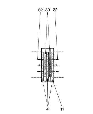
In the single figure of the drawing there is shown a
vertlcal cross-sectional view of a movable center mold clampin~
plate according to the present invention.


/AR clearly seen in the drawing, a movable center mold
clamping plate 4' consists of three parts with melt conduction
system 30 arranged between the three parts. Melt conductlon
system 30 is comprised of melt conduction rails. The mold
clamping plate 4' ls clamped together by means of one or a
number of high~speed clamping devices (not shown), thereby
forming a single unit. Reference numeral 32 denotes the
nozzles and numeral 11 the bearing for the movable center mold

clamping plate.

12~i4909

While only a single embodiment of the present invention ha~
been shown and described, it will be obvlous that many changes
and modifications may be made thereunto wlthout departing from
the spirit and scope of the invention.
Representative Drawing
A single figure which represents the drawing illustrating the invention.
Administrative Status

For a clearer understanding of the status of the application/patent presented on this page, the site Disclaimer , as well as the definitions for Patent , Administrative Status , Maintenance Fee  and Payment History  should be consulted.

Administrative Status

Title Date
Forecasted Issue Date 1990-01-30
(22) Filed 1986-09-25
(45) Issued 1990-01-30
Deemed Expired 1992-08-01

Abandonment History

There is no abandonment history.

Payment History

Fee Type Anniversary Year Due Date Amount Paid Paid Date
Application Fee $0.00 1986-09-25
Registration of a document - section 124 $0.00 1987-01-08
Owners on Record

Note: Records showing the ownership history in alphabetical order.

Current Owners on Record
STUBBE GMBH
Past Owners on Record
KAADEN, HANS-HEINRICH
Past Owners that do not appear in the "Owners on Record" listing will appear in other documentation within the application.
Documents

To view selected files, please enter reCAPTCHA code :


To view images, click a link in the Document Description column. To download the documents, select one or more checkboxes in the first column and then click the "Download Selected in PDF format (Zip Archive)" or the "Download Selected as Single PDF" button.

List of published and non-published patent-specific documents on the CPD .

If you have any difficulty accessing content, you can call the Client Service Centre at 1-866-997-1936 or send them an e-mail at CIPO Client Service Centre.


Document
Description 
Date
(yyyy-mm-dd) 
Number of pages   Size of Image (KB) 
Representative Drawing 2001-04-24 1 6
Drawings 1993-09-15 1 11
Claims 1993-09-15 2 40
Abstract 1993-09-15 1 34
Cover Page 1993-09-15 1 14
Description 1993-09-15 4 106