Language selection

Search

Patent 1265069 Summary

Third-party information liability

Some of the information on this Web page has been provided by external sources. The Government of Canada is not responsible for the accuracy, reliability or currency of the information supplied by external sources. Users wishing to rely upon this information should consult directly with the source of the information. Content provided by external sources is not subject to official languages, privacy and accessibility requirements.

Claims and Abstract availability

Any discrepancies in the text and image of the Claims and Abstract are due to differing posting times. Text of the Claims and Abstract are posted:

  • At the time the application is open to public inspection;
  • At the time of issue of the patent (grant).
(12) Patent: (11) CA 1265069
(21) Application Number: 1265069
(54) English Title: ELEVATOR ESCAPE STRUCTURE
(54) French Title: STRUCTURE D'EVACUATION D'UNE CABINE D'ASCENSEUR EN PANNE
Status: Expired and beyond the Period of Reversal
Bibliographic Data
Abstracts

English Abstract


F4F/4.162
ELEVATOR ESCAPE STRUCTURE
Abstract of the Disclosure
This invention relates to an elevator shaft struc-
ture in a building about an elevator to aid escape from
the elevator upon a power failure; and it includes a
structure defining an elevator shaft for an elevator cab
which provides a rear shaft wall with a stairway extend-
ing outwardly from the rear wall for travel between the
floors and, in the elevator cab, a rear door is provided
for escape from the elevator onto the emergency stairway.


Claims

Note: Claims are shown in the official language in which they were submitted.

F4G/4.162
The embodiments of the invention in which an exclusive
property or privilege is claimed are defined as follows:
1. In a multi story building 12 having at least one
floor at one level and another floor at another level, and
having an elevator shaft with a front elevator lobby wall
with an entrance opening into said shaft at each floor for
ingress and egress,
a pair of side walls each extending from the front
elevator lobby wall to an oppositely disposed end of each
side wall,
an elevator cab sized to move vertically between the
front and side walls in the shaft, and
said cab including lift means operatively connecting
the cab and the building,
the improvement comprising:
a) a rear wall disposed parallel to the front wall
and spaced from the end of the side wall a predetermined
distance,
b) a stair structure fixedly secured to the building
and disposed between the rear wall and the ends of the side
walls,
c) said stair structure being elongated and extend-
ing substantially between one of the pairs of side wall
ends and the one floor and the other pairs of side wall
ends at the other floor,
d) the elevator cab having an elevator rear wall
disposed substantially between the ends of the pair of side
walls and a door opening in the elevator rear wall substan-
tially extending across the entire elevator cab and along a

F4G/4.162
majority of the length of the stair structure,
e) a door mounted in said elevator cab and com-
prising a plurality of segments movable relative to one
another and selectively positionable relative to the door
opening to open at least either of two opposite ends of the
door opening for direct access to the stair structure, and
f) the stair structure angularly oriented between
floors and accessible from the elevator cab through at
least one of the two opposite ends of the door opening
regardless of the level of the elevator cab relative to the
stair structure.
2. The device as set forth in claim 1 wherein said
lift means includes a disconnecting switch means, said
switch means being normally closed and including means to
open a circuit structured to connect a power supply and
said lift means for interruption of power to said lift
means, said switch means remaining open until selectively
closed when power is interrupted to said lift means.
3. The device as set forth in claim 1 wherein said
door comprises a sliding panel construction including a
first, second and third segment spanning said elevator rear
wall and said segments being slidable relative to one
another in covering relation to said door opening, each of
said segments being selectively positionable relative to
the other segments to provide access through said door
opening to said stair structure at different levels between
said floors.

F4G/4.162
4. The device as set forth in claim 1 wherein guide
means are provided along said stairway structure adjacent
said ends of said side walls.

Description

Note: Descriptions are shown in the official language in which they were submitted.


F4F/4.162
S P E C I F I C A T I O N
ELEVATOR ESCAPE STRUCTURE
This invention relates to an escape device for an
elevator, which is equipped with a rear door as well as
the conventional front door; and, more particularly, to
an eleva-tor shaft with a rear wall provided with a stair-
way between the floor of a building as shown and descri-
bed, so that if the elevator is stopped between floors,
for example in a hurricane power failure, or okher type
failure, people in the elevator may exit the elevator
through the rear door and onto the s-tairway to proceed up
or down it to one of the building floors.
In the past, notwithstanding every effort to provide
devices to insure that elevators do not get stuck between
floors, it does occur all too often that people are
trapped, sometimes for extended periods of time which is
very un~nerving and, in some cases, highly dangerous.
To provide an escape, some eleva~or roofs are
provided with escape hatches; however, this is at best an
~ attempt to provide a difficult and cumbersome escape
path. Accordingly, efforts have continued to solve the
elevator problem and efforts in this regard are ~ound in
the prior art, for example in the following U.S. Patents:
373,587; 1,977,706; 3,012,633; and 3,~58,885.
It is an object of this invention to provide an
elevator shaft which provides, between f]oors and e~-
tending into the shaf~ and the rear wall, a stairway
means so that, when an elevator cab is stopped be~een
floors, a rear door of the elevator cab may be opened and

F4F/4.162
people within the elevator may pass -through the rear door
onto the stairway to move up or down to the building
floors proper and escape from the elevator cab.
Accordingly, it is an object of this invention -to
provide an improved safety device for use in elevators
and which is strong and durable, part of the building,
and which is permanent in itæ providing for the escape of
people trapped within an elevator in the building.
In accordance with these and other objects which
will become apparent hereinafter, the instant invention
will now be described with reference to -the accompanying
drawings in which:
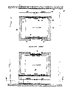
Figure 1 is a plan view of an elevator lobby of a
building constructed in accordance with this invention.
Figure 2 is an elevation view in cross-section
through one of the emergency stairwells and taken on the
plane indicated by the line 2-2 of Figure 1 and looking
in the direction of the arrows.
Figure 3 is a circuit diagram illustrating a master
switch and conventional drive means of the lift or eleva-
tor.
Reerring to the drawings wherein like reference
characters designate like or corresponding parts through-
out the several views, there is shown a multi-story
building having a wall 12 and elevator shafts such as 14
in the building defined by a vertical front wall 16 and
vertical side walls 20 and 22 extending from the front
wall and ending at turned in ends as at 24 and 26. The
elevator shaft 14 is sized for vertical movement of an
elevator cab in the shaft, and it is shown at several

F4F/4.16~
~51)~
locations, see Figure 2, as at 28, 28' and 28".
The floors of the building are represented as at 50,
52, 54 and 56 and a pair of access doors such as 58 and
60 are provided onto each of the floors from the elevator
shaft. It will be seen that there has been provided a
conventional lift drive means 30 which is suitably con-
nected to move the lift or elevator cab vertically in the
shaft. Between the floors, that is between the doors,
for example 57 and 58, a stairway flight such as 42, 4~'
and 42" is provided. It is supported in cantilever
fashion by the building and more par-ticularly the rear
elevator shaft wall. It extends from adjacent one of the
side walls to thP other of the side walls and out into
the elevator shaft from the rear wall in close ~ide-by-
side relation to the ends of the side walls with the
outer edge of the stairway in effect providing a partial
rear wall for the elevator shaft. Within the elevator
cab, in the rear wall 44, a door 46, preferably a by-pass
or sliding door is provided in closing relation to a door
opening 48. This door is opposite the main entrance door
at the front of the cab 76 which opens automatically.
The rear door 46 is operated manually or electrically by
sliding it either to the left or to the righk as required
when the elevator has been stuck between floors, so that
one may open it and step out through opening 48 substan-
tially along the length of the opening between opposite
ends 48' (see Fig. 2) onto the stairway. It will be
noted ~hat the elevator may be in various positions
between a f1oor but that the arrangement of the rear
doors in the center of the rear wall of the elevator cab

F4F/4.162
~5~
provides ~hat a person may escape -therefrom at any level
in which the elevator has stopped.
It is thus seen that -there has been provided a
simple and inexpensive structure by which one may provide
escape for elevators stuck between floors in new con-
structions.
As shown in Figure 3, the drive means 30 includes in
a preferred embodiment the motor and a switching panel 31
to which conductors 33 and 35 supply power and in which
there is provided a master switch 39. In use, the rear
door of the elevator cab may be adapted to open the main
power circui-t so that when the power is off, the switch
39 will be opened so that the elevator cannot move even
if power is restored and people may escape from the
elevator without fear of injury. In the preferred em-
bodiment, the main switch will open if there is a power
failure and cannot be closed except by a positive act.
Also, if power fails an emergency battery powered light
system, not shown, for the cab, shaft and stairway will
be activated.
While the instant invention has been shown and de-
scribed herein in what is conceived to be the most prac-
tical and preferred embodiment, it is recognized that
departures may be made therefrom within the scope of the
invention, which is therefore not to be limited to the
details disclosed herein but is to be accorded the full
scope of the claims so as to embrace any and all egui-
valent apparatus and articles.
,,
1, ; , "

Representative Drawing
A single figure which represents the drawing illustrating the invention.
Administrative Status

2024-08-01:As part of the Next Generation Patents (NGP) transition, the Canadian Patents Database (CPD) now contains a more detailed Event History, which replicates the Event Log of our new back-office solution.

Please note that "Inactive:" events refers to events no longer in use in our new back-office solution.

For a clearer understanding of the status of the application/patent presented on this page, the site Disclaimer , as well as the definitions for Patent , Event History , Maintenance Fee  and Payment History  should be consulted.

Event History

Description Date
Time Limit for Reversal Expired 2005-01-31
Letter Sent 2004-01-30
Inactive: Entity size changed 2002-02-11
Grant by Issuance 1990-01-30

Abandonment History

There is no abandonment history.

Fee History

Fee Type Anniversary Year Due Date Paid Date
MF (category 1, 8th anniv.) - small 1998-01-30 1998-01-27
MF (category 1, 9th anniv.) - small 1999-02-01 1998-12-08
MF (category 1, 10th anniv.) - small 2000-01-31 2000-01-11
MF (category 1, 11th anniv.) - small 2001-01-30 2001-01-26
MF (category 1, 12th anniv.) - standard 2002-01-30 2002-01-30
MF (category 1, 13th anniv.) - standard 2003-01-30 2002-12-19
Owners on Record

Note: Records showing the ownership history in alphabetical order.

Current Owners on Record
SAMUEL GOMEZ
Past Owners on Record
None
Past Owners that do not appear in the "Owners on Record" listing will appear in other documentation within the application.
Documents

To view selected files, please enter reCAPTCHA code :


To view images, click a link in the Document Description column. To download the documents, select one or more checkboxes in the first column and then click the "Download Selected in PDF format (Zip Archive)" or the "Download Selected as Single PDF" button.

List of published and non-published patent-specific documents on the CPD .

If you have any difficulty accessing content, you can call the Client Service Centre at 1-866-997-1936 or send them an e-mail at CIPO Client Service Centre.


Document
Description 
Date
(yyyy-mm-dd) 
Number of pages   Size of Image (KB) 
Drawings 1993-10-07 2 88
Cover Page 1993-10-07 1 16
Abstract 1993-10-07 1 16
Claims 1993-10-07 3 84
Descriptions 1993-10-07 4 158
Representative drawing 2001-10-02 1 23
Maintenance Fee Notice 2004-03-29 1 173
Fees 1998-01-27 1 40
Fees 1998-12-08 1 41
Fees 2002-01-30 1 38
Correspondence 2001-01-26 1 23
Fees 1998-12-08 1 40
Fees 2001-01-26 1 21
Fees 1998-01-27 1 40
Fees 1995-11-28 1 45
Fees 1997-01-29 1 63
Fees 1994-12-07 1 47
Fees 1992-12-09 1 25
Fees 1989-11-08 1 18
Fees 1993-11-15 1 26
Fees 1991-10-29 1 47