Sélection de la langue

Search

Sommaire du brevet 1265069 

Énoncé de désistement de responsabilité concernant l'information provenant de tiers

Une partie des informations de ce site Web a été fournie par des sources externes. Le gouvernement du Canada n'assume aucune responsabilité concernant la précision, l'actualité ou la fiabilité des informations fournies par les sources externes. Les utilisateurs qui désirent employer cette information devraient consulter directement la source des informations. Le contenu fourni par les sources externes n'est pas assujetti aux exigences sur les langues officielles, la protection des renseignements personnels et l'accessibilité.

Disponibilité de l'Abrégé et des Revendications

L'apparition de différences dans le texte et l'image des Revendications et de l'Abrégé dépend du moment auquel le document est publié. Les textes des Revendications et de l'Abrégé sont affichés :

  • lorsque la demande peut être examinée par le public;
  • lorsque le brevet est émis (délivrance).
(12) Brevet: (11) CA 1265069
(21) Numéro de la demande: 1265069
(54) Titre français: STRUCTURE D'EVACUATION D'UNE CABINE D'ASCENSEUR EN PANNE
(54) Titre anglais: ELEVATOR ESCAPE STRUCTURE
Statut: Périmé et au-delà du délai pour l’annulation
Données bibliographiques
Abrégés

Abrégé anglais


F4F/4.162
ELEVATOR ESCAPE STRUCTURE
Abstract of the Disclosure
This invention relates to an elevator shaft struc-
ture in a building about an elevator to aid escape from
the elevator upon a power failure; and it includes a
structure defining an elevator shaft for an elevator cab
which provides a rear shaft wall with a stairway extend-
ing outwardly from the rear wall for travel between the
floors and, in the elevator cab, a rear door is provided
for escape from the elevator onto the emergency stairway.

Revendications

Note : Les revendications sont présentées dans la langue officielle dans laquelle elles ont été soumises.


F4G/4.162
The embodiments of the invention in which an exclusive
property or privilege is claimed are defined as follows:
1. In a multi story building 12 having at least one
floor at one level and another floor at another level, and
having an elevator shaft with a front elevator lobby wall
with an entrance opening into said shaft at each floor for
ingress and egress,
a pair of side walls each extending from the front
elevator lobby wall to an oppositely disposed end of each
side wall,
an elevator cab sized to move vertically between the
front and side walls in the shaft, and
said cab including lift means operatively connecting
the cab and the building,
the improvement comprising:
a) a rear wall disposed parallel to the front wall
and spaced from the end of the side wall a predetermined
distance,
b) a stair structure fixedly secured to the building
and disposed between the rear wall and the ends of the side
walls,
c) said stair structure being elongated and extend-
ing substantially between one of the pairs of side wall
ends and the one floor and the other pairs of side wall
ends at the other floor,
d) the elevator cab having an elevator rear wall
disposed substantially between the ends of the pair of side
walls and a door opening in the elevator rear wall substan-
tially extending across the entire elevator cab and along a

F4G/4.162
majority of the length of the stair structure,
e) a door mounted in said elevator cab and com-
prising a plurality of segments movable relative to one
another and selectively positionable relative to the door
opening to open at least either of two opposite ends of the
door opening for direct access to the stair structure, and
f) the stair structure angularly oriented between
floors and accessible from the elevator cab through at
least one of the two opposite ends of the door opening
regardless of the level of the elevator cab relative to the
stair structure.
2. The device as set forth in claim 1 wherein said
lift means includes a disconnecting switch means, said
switch means being normally closed and including means to
open a circuit structured to connect a power supply and
said lift means for interruption of power to said lift
means, said switch means remaining open until selectively
closed when power is interrupted to said lift means.
3. The device as set forth in claim 1 wherein said
door comprises a sliding panel construction including a
first, second and third segment spanning said elevator rear
wall and said segments being slidable relative to one
another in covering relation to said door opening, each of
said segments being selectively positionable relative to
the other segments to provide access through said door
opening to said stair structure at different levels between
said floors.

F4G/4.162
4. The device as set forth in claim 1 wherein guide
means are provided along said stairway structure adjacent
said ends of said side walls.

Description

Note : Les descriptions sont présentées dans la langue officielle dans laquelle elles ont été soumises.

F4F/4.162
S P E C I F I C A T I O N
ELEVATOR ESCAPE STRUCTURE
This invention relates to an escape device for an
elevator, which is equipped with a rear door as well as
the conventional front door; and, more particularly, to
an eleva-tor shaft with a rear wall provided with a stair-
way between the floor of a building as shown and descri-
bed, so that if the elevator is stopped between floors,
for example in a hurricane power failure, or okher type
failure, people in the elevator may exit the elevator
through the rear door and onto the s-tairway to proceed up
or down it to one of the building floors.
In the past, notwithstanding every effort to provide
devices to insure that elevators do not get stuck between
floors, it does occur all too often that people are
trapped, sometimes for extended periods of time which is
very un~nerving and, in some cases, highly dangerous.
To provide an escape, some eleva~or roofs are
provided with escape hatches; however, this is at best an
~ attempt to provide a difficult and cumbersome escape
path. Accordingly, efforts have continued to solve the
elevator problem and efforts in this regard are ~ound in
the prior art, for example in the following U.S. Patents:
373,587; 1,977,706; 3,012,633; and 3,~58,885.
It is an object of this invention to provide an
elevator shaft which provides, between f]oors and e~-
tending into the shaf~ and the rear wall, a stairway
means so that, when an elevator cab is stopped be~een
floors, a rear door of the elevator cab may be opened and

F4F/4.162
people within the elevator may pass -through the rear door
onto the stairway to move up or down to the building
floors proper and escape from the elevator cab.
Accordingly, it is an object of this invention -to
provide an improved safety device for use in elevators
and which is strong and durable, part of the building,
and which is permanent in itæ providing for the escape of
people trapped within an elevator in the building.
In accordance with these and other objects which
will become apparent hereinafter, the instant invention
will now be described with reference to -the accompanying
drawings in which:
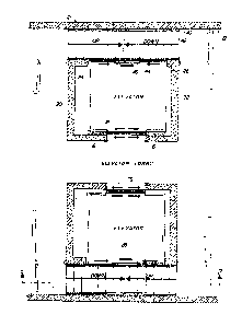
Figure 1 is a plan view of an elevator lobby of a
building constructed in accordance with this invention.
Figure 2 is an elevation view in cross-section
through one of the emergency stairwells and taken on the
plane indicated by the line 2-2 of Figure 1 and looking
in the direction of the arrows.
Figure 3 is a circuit diagram illustrating a master
switch and conventional drive means of the lift or eleva-
tor.
Reerring to the drawings wherein like reference
characters designate like or corresponding parts through-
out the several views, there is shown a multi-story
building having a wall 12 and elevator shafts such as 14
in the building defined by a vertical front wall 16 and
vertical side walls 20 and 22 extending from the front
wall and ending at turned in ends as at 24 and 26. The
elevator shaft 14 is sized for vertical movement of an
elevator cab in the shaft, and it is shown at several

F4F/4.16~
~51)~
locations, see Figure 2, as at 28, 28' and 28".
The floors of the building are represented as at 50,
52, 54 and 56 and a pair of access doors such as 58 and
60 are provided onto each of the floors from the elevator
shaft. It will be seen that there has been provided a
conventional lift drive means 30 which is suitably con-
nected to move the lift or elevator cab vertically in the
shaft. Between the floors, that is between the doors,
for example 57 and 58, a stairway flight such as 42, 4~'
and 42" is provided. It is supported in cantilever
fashion by the building and more par-ticularly the rear
elevator shaft wall. It extends from adjacent one of the
side walls to thP other of the side walls and out into
the elevator shaft from the rear wall in close ~ide-by-
side relation to the ends of the side walls with the
outer edge of the stairway in effect providing a partial
rear wall for the elevator shaft. Within the elevator
cab, in the rear wall 44, a door 46, preferably a by-pass
or sliding door is provided in closing relation to a door
opening 48. This door is opposite the main entrance door
at the front of the cab 76 which opens automatically.
The rear door 46 is operated manually or electrically by
sliding it either to the left or to the righk as required
when the elevator has been stuck between floors, so that
one may open it and step out through opening 48 substan-
tially along the length of the opening between opposite
ends 48' (see Fig. 2) onto the stairway. It will be
noted ~hat the elevator may be in various positions
between a f1oor but that the arrangement of the rear
doors in the center of the rear wall of the elevator cab

F4F/4.162
~5~
provides ~hat a person may escape -therefrom at any level
in which the elevator has stopped.
It is thus seen that -there has been provided a
simple and inexpensive structure by which one may provide
escape for elevators stuck between floors in new con-
structions.
As shown in Figure 3, the drive means 30 includes in
a preferred embodiment the motor and a switching panel 31
to which conductors 33 and 35 supply power and in which
there is provided a master switch 39. In use, the rear
door of the elevator cab may be adapted to open the main
power circui-t so that when the power is off, the switch
39 will be opened so that the elevator cannot move even
if power is restored and people may escape from the
elevator without fear of injury. In the preferred em-
bodiment, the main switch will open if there is a power
failure and cannot be closed except by a positive act.
Also, if power fails an emergency battery powered light
system, not shown, for the cab, shaft and stairway will
be activated.
While the instant invention has been shown and de-
scribed herein in what is conceived to be the most prac-
tical and preferred embodiment, it is recognized that
departures may be made therefrom within the scope of the
invention, which is therefore not to be limited to the
details disclosed herein but is to be accorded the full
scope of the claims so as to embrace any and all egui-
valent apparatus and articles.
,,
1, ; , "

Dessin représentatif
Une figure unique qui représente un dessin illustrant l'invention.
États administratifs

2024-08-01 : Dans le cadre de la transition vers les Brevets de nouvelle génération (BNG), la base de données sur les brevets canadiens (BDBC) contient désormais un Historique d'événement plus détaillé, qui reproduit le Journal des événements de notre nouvelle solution interne.

Veuillez noter que les événements débutant par « Inactive : » se réfèrent à des événements qui ne sont plus utilisés dans notre nouvelle solution interne.

Pour une meilleure compréhension de l'état de la demande ou brevet qui figure sur cette page, la rubrique Mise en garde , et les descriptions de Brevet , Historique d'événement , Taxes périodiques et Historique des paiements devraient être consultées.

Historique d'événement

Description Date
Le délai pour l'annulation est expiré 2005-01-31
Lettre envoyée 2004-01-30
Inactive : Grandeur de l'entité changée 2002-02-11
Accordé par délivrance 1990-01-30

Historique d'abandonnement

Il n'y a pas d'historique d'abandonnement

Historique des taxes

Type de taxes Anniversaire Échéance Date payée
TM (catégorie 1, 8e anniv.) - petite 1998-01-30 1998-01-27
TM (catégorie 1, 9e anniv.) - petite 1999-02-01 1998-12-08
TM (catégorie 1, 10e anniv.) - petite 2000-01-31 2000-01-11
TM (catégorie 1, 11e anniv.) - petite 2001-01-30 2001-01-26
TM (catégorie 1, 12e anniv.) - générale 2002-01-30 2002-01-30
TM (catégorie 1, 13e anniv.) - générale 2003-01-30 2002-12-19
Titulaires au dossier

Les titulaires actuels et antérieures au dossier sont affichés en ordre alphabétique.

Titulaires actuels au dossier
SAMUEL GOMEZ
Titulaires antérieures au dossier
S.O.
Les propriétaires antérieurs qui ne figurent pas dans la liste des « Propriétaires au dossier » apparaîtront dans d'autres documents au dossier.
Documents

Pour visionner les fichiers sélectionnés, entrer le code reCAPTCHA :


Pour visualiser une image, cliquer sur un lien dans la colonne description du document. Pour télécharger l'image (les images), cliquer l'une ou plusieurs cases à cocher dans la première colonne et ensuite cliquer sur le bouton "Télécharger sélection en format PDF (archive Zip)" ou le bouton "Télécharger sélection (en un fichier PDF fusionné)".

Liste des documents de brevet publiés et non publiés sur la BDBC .

Si vous avez des difficultés à accéder au contenu, veuillez communiquer avec le Centre de services à la clientèle au 1-866-997-1936, ou envoyer un courriel au Centre de service à la clientèle de l'OPIC.


Description du
Document 
Date
(aaaa-mm-jj) 
Nombre de pages   Taille de l'image (Ko) 
Dessins 1993-10-07 2 88
Page couverture 1993-10-07 1 16
Abrégé 1993-10-07 1 16
Revendications 1993-10-07 3 84
Description 1993-10-07 4 158
Dessin représentatif 2001-10-02 1 23
Avis concernant la taxe de maintien 2004-03-29 1 173
Taxes 1998-01-27 1 40
Taxes 1998-12-08 1 41
Taxes 2002-01-30 1 38
Correspondance 2001-01-26 1 23
Taxes 1998-12-08 1 40
Taxes 2001-01-26 1 21
Taxes 1998-01-27 1 40
Taxes 1995-11-28 1 45
Taxes 1997-01-29 1 63
Taxes 1994-12-07 1 47
Taxes 1992-12-09 1 25
Taxes 1989-11-08 1 18
Taxes 1993-11-15 1 26
Taxes 1991-10-29 1 47