Note: Descriptions are shown in the official language in which they were submitted.
533~
TORCH FOR FABRICATING
OPTICAI FIBER PREFORM
BACKGROUND OF THE INVENTION
This invention relates to a torch for fabricating an optical
fiber preform in case of manufacturing a porous glass preform for a
communication or optics throu~h a VAD method or an OVD method.
A VAD metbod or an OVD method ~hich mi~es less impurities and
OH group is employed as means for fabricatin~ a porous ~lass preform
for an optical fiber, an image fiber, a light guide or a rod lens~
Each of the above-mentioned methods supplies raw gasJ
combustible gas and combustion supporting gas or these gases and
sealing gas to a torch for fabricating a porous glass preform,
produces soot-state porous glass preform by flame hydrolysis and/or
thermal oxidation, and accumulates the preform in a desire~ shape
such as a rod or tube shape.
I torch used in these methods has a multiwall tube strocture of
triple or more ~all tubes. When the torch is formed, for e~ample,
of a ~uadruple ~all tube structure, the passages from the center to
the outermost periphery of the torch are used as a raw gas injection
passage (first passage: at the center), a sealing gas iniection
passage (second passage), a combustible gas injection passage (thlrd
passage~ and a combustlon sUppOrtine gas injeotlon passa~e ~fourth
passage: the outermost periphery).
The raw gas contains SICl4 of main raw~gas, and GeCl~,~POCl3,
BCla, of doping ra~ materials. The combus~tible gas contains
hydrogen~(Hz), methane, propane, butane or a mi~ture gas of any two
or more gases. The combustion supporting gas contains oxygen (Oz),
and the sealing gas contains Ar and/or other inert gas.
Principles of accumulating the optical fiber preforms in the
VAD and OVD methods are fundamentally the samey but the VAD method
'
~ 533~
accumulates the optical fiber preform on the lower end of a vertical
target drawn ~hile rotating, and the OVD method accumulates the
optical fiber preform on the outer periphery of a mandrel rotating
in a horizontal state.
The porous glass preform thus accumulated and formed through
the above methods is dehydrated and transparently vitrified by the
following heat treatment to become a transparent preform which
contains no air bubble.
In case of the above-mentioned YhD method, the porous glass
preform is gro~n a~ially by the accumulation of the optical fiber
preform. In this case, as the preform is gro~n~ a large own weight
is applied to the preform. Thus, when a long and large porous glass
preform is produced, the preform tends to be damaged by the weight
of itself.
Therefore, it is necessar~ to improve the strength of the
preform to enhance the accumulating density of the optical fiber
preform when fabricating the large-size porous glass preform by
the VA~ method.
In case of the OVD method for accumulating an optical fiber
preform on the outer periphery of a mandrel of horizontal state, no
damaee occurs~in the porous glass preform as observed in the VAD
method~ but as the optical fiber preform is accumulated, the
diameter of the preform increases so that the surface area of the
preform gradually increases. Thus, the quantity of heat of unit
area/unit time of a flame generated from a toroh to the surface of
the preform alters, and the quantity of heat at the end of
accumulating the optical fiber preform becomes considerably smaller
than that at the initial time.
The shrink-fitting degree of the porous glass preform becomes
insuficient to~ard the end of the accumulation due to such a
- 2 -
~ Z16533~
phenomenon so that there is a difference in the density of the
optical fiber preform o~er the radlal direction of the preform
between the central portion and the peripheral portion.
The density of the porous glass preform is perferably 074 to
1.0 g/cm~. If the density of the porous glass preform decreases
belo~ this value due to the insufficient shrink-fitting degree, a
crack occurs in the preform along the longitudinal direction of the
preform at growin~ or cooling time.
To eliminate this drawback, the rotating speed of the preform
is decelerated in response to the growth of the preform or the
quantity of combustion gas is increases.
However, in the former case that the rotating speed of the
preform is decelerated, a cause of an uneven surface is produced on
the surface of the porous glass preform or an improper outer
diameter is produced in the preform.
In the latter case that the quantity of combustion gas is
increased~ this method depends upon an uncertain process of setting
experimentally the increasing amount of the gas and is very
difficult to gradually increase the combustible gas to eliminate the
uneven accumulating density of the optical fiber preform by
preventing the preform from cracking when considering that a flame
generated from a torch is of a converging shape.
:~
As described above, the method of fabricating the porous glass
preform with a conventional torque of multiwall tube structure can
~hardly provide a large-size preform~having unlform optical fiber
preform density ~ithout crack nor improper outer diameter.
SUMMARY OF TH~ INVENTION
Accordin~ly, an obJect of this invention is to provide a torch
for fabricating an optical fiber preform capable of stably
manufacturing a porous glass preformO
- 3 -
.. ~ ,.
. ' ~: ' ``'': '
~i533~
In order to achieve the above and other objects of this
invention, there is provided according to an aspect of this
invention a torch for fabricating an optical fiber Preform
comprising a plurality of ra~ gas injection Passages at the center
of the torch, a plurality of small-diameter combustion supporting
gas injection passages independent of each other and disposed to
surround the raw gas injection passages on the outer periphery of
the ra~ gas injection passage disposed at the center of the torch,
and an annular combustible gas injection passage provided on the
periphery of each of the small-diameter combustion supporting gas
injection passages.
According to another aspect of this invention, there is
provided to achieve the above and other objects of this invention
a torch for fabricatin~ an optical fiber preform comprising a
plurality of ra~ gas injection passages at the center of the torch,
a plurality of small-diameter combustion supporting gas injection
passages independent of each other and disposed to surround the raw
gas ~injection passages on the outer periphery of the raw gas
injection passages disposed at the center of the torch, an annular
combustible gas injection passa~e providFd on the periphery of
each of the small-diameter combustion supporting gas injection
passages, and an annular combustion supporting gas inJection passage
provided on the outer periphery of the annular combustion gas
injection passage.
According to still another aspect of this invention, there is
provided to achieve the above and other objects of the invention a
torch for fabricating an optical fiber preform comprising a
plurality of raw gas iniection passages at the center of the torch,
a first annular sealing gas injection passage provided on the outer
periphery of the ra~ gas injection passage disposed at the~ center
~ 3 3 ~
of the torch 9 a PluralitY of small diameter combustion supporting
gas injection passages independent of each other and disposed to
surround the annular sealing ~as injection passage on the outer
periphery of the firæt annular sealing gas injection passage, an
annular combustible gas injection passage provided on the periphery
of each of the small-diameter combustion supporting gas injection
passages, a second sealing gas injection passage provided on the
outer periphery of the annular combusti~le gas injection passage,
and an annular combustion supporting gas injection passage provided
on the outer periphery of the second sealing gas injection
passage.
The above and other related objects and features of the
invention will be apparent from a reading of the following
description of the disclosure found in the accompanying dra~ings and
the novelty thereof pointed out in the appended claims.
BRIEF DESCRIPTION OF THE DRAWINGS
Fig. 1 is a plan vie~ showing a first embodiment of a torch
according to the present invention;
Fig. 2 is a longitudinal sectional vie~ of the torch of Fig.
; Fig. 3 is a longitudinal sectional vie~ of an essential
portion of a second embodiment of a torch according to the present
inven~ion; : ~
Fig. 4 is a Plan view sho~ing a third embodiment of a torch
acoordine to the inventlon;
Fig. 5 is a schematic vie~ showing a VAD method using the
torch of th~e invention; and
Fig. 6 is a schematic vie~ showing an OVD method using the
torch of the invention.
- 5 -
:
3 3 ~
~ESCRIPTION OF THE PREFERRED EMBODIM~NTS
Embodiments of a torch for fabricating an optical fiber Preform
according to the pres0nt invention will be described in detail ~ith
reference to the accompanying dra~ings.
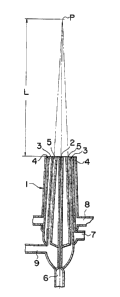
` Figso 1 and 2 show a first embodiment of a torch according to
the present invention. A torch 1 of a multi~all tube structure
sho~n in Figs. 1 and 2 has a raw gas injection passage 2 provided at
the center of the torch 1, an annular combustible gas injection
passa~e 3 provided on the outer periphery of the raw gas injection
passage 2, an annular combustion supporting gas injection passage 4
provided on the outer periphery of the combustible gas inject:ion
passage 3, and a plurality of small-diameter combustion supporting
gas injection passages 5 independent of each other and provided at
an (equal) interval circumferentially in the combustible gas
injection passage 3.
In case of such a torch 1, as apparent from Fig. 1, the small-
diameter combustion supporting gas injection passages 5 disposed in
the co~bustion gas injection passage 3 surround the ra~ gas
injection passage 2 disposed at the center of the torch 1.
Further, the small-diameter combustion supporting gas injection
passages 5 are, as apparent from Fig. 27 directed toward a point P
on the center line of the rau gas înjection passage 2, of so-called
a focus converging type.
A distance L from the end of the torch 1 to the polnt P is
ordinarily set to a range of approx. 30 to 350 mm, and more
particularly to L=approx. 200 mm.
hs shown in Fig. 2, gas inlets 6, 7, 8 and 9 are provided
correspondingly to the gas injection passages 2, 3, ~ and 5 at the
lower portion of the torch 1.
A torch 1 of multiwall tube structure of a secGnd embodiment of
~ 2 ~ S 3 ~ ~
the inYention shown in Fig. 3 is constructed fundamentally the same
as that in Figs. 1 and ~ e~cept a ra~ gas injection passage 2, an
annular combustible gas injection passage 3, an annular combustion
supporting gas injection passage 4 and a small-diameter combustion
supporting gas injection Passage 5 are disposed in parallel with
each other and that the injection passages 3, 5, 2 and 4 ar0
sequentially protruded at the ends in the relative relationship of
the passages.
Further, in the torch 1 of Fig. 3, the ends of the raw gas
injection passage 2 and the small-diameter combustion supporting gas
injection Passage 5 are formed in spherical shape.
It is noted that the constructions o-f the difference (uneven
state) of the projecting states of the ends of the iniection
passages or the spherical shape of the ends of the injection
passages in the second embodiment of the invention may also be
employed in the first embodiment in Figs. 1 and 2 and in the
following third embodiment of the invention as will be described
later ~ithin the spirit and scope of the invention.
Further, it is also noted that in the torch 1 of the above-
mentloned first and second embodiments, the annular co~bustion
supporting~gas iniection passage 4 may be omitted ~ithin the spirit
and scope of the invention.
A torch 1 of multi~all tube structure of a third embodiment of
the inYention sho~n in Fig. 4 is cons~tructed such that a ra~ gas
injection passage 2, a first annular sealing gas injection passage
10, an annular combustible gas injection passage 3, a second annular
sealing gas injection passage 11 and an annular combustion
supportine gas iniection passage 4 are sequentially provided from
the center of the torch 1 to~ard the outer periphery and a plurality
of small-diameter co~bustion supporting gas injection passages 5
-- 7 --
~L~ ~ 5 3 ~ ~
independent of each other are provided at an interval in the
circumferential direction ~ithin the annular combustion gas
injection passage 3.
As further embodiments, a plurality of raw gas injection
passages and/or a plurality of combustible gas injection passages
may be provided.
For example, in these embodiments, ~hen two (or more) adjacent
ra~ gas injection Passages are provided at the center of the torch 1,
other gas injection passages provided in a multiwall tube structure
is formed in an elliptical shape on the outer periphery of the raw
gas injection passage. ~hen the smalI-diameter combustion
supporting gas injection passages are formed in a focus converging
type in this case, two focuses of the ellipse are defined to
correspond to the small-diameter combustion supporting gas injection
passages.
When t~o annular combustible gas 1njection passages are
provided, one may be disposed at the position in t:he previous
embod1m:ents, and the other may be disposed,~for example, on the
outermost periphery of the torch 1.
The tubular or cylindrical material of the torch 1 iF formed of
a quart2 glass or ceramics having high heat resistance, and may also
: : :
be formed at ths end sides o~the gas~ 1njection~paSSages of a quartz
glass or ceramics and at the remsinder of a metal hav1ng excellent
~corroslon rssistance and medicine resistance.
Figs. 5 and 6 schematically sho~ a VAD method and an OVD method
~ - : :
executed by the torch 1 of the invention.
In the VAD method in Fig. 5, a system has a reaction ves~el 21
which contains an exhaust conduit 22, ao electric furnace 23 ~hich
contains a heater (an electric heater) 24 provided at the top of the
vessel 21, a target 25 of quartz and a rotary drawing unit 26 o~ the
- 8 ~
~ 2Ç~533~
target 25. According to the VAD method in this known system, an
optical fiber pre-form produced through the torch 1 is sequentially
acccumulated on the lo~er end of the target 25 to form a porous
glass preform 27, the porous glass preform 27 is transparently
vitrified through the electric furnace 23 to provide a rod-shaped
transparent glass preform 28.
In the OVD method in Fig. 6, this system has a rotating and
reciprocating type drive unit 31, and a mandrel 32 of quartz pipe
supported by the drive unit 31. According to the OYD method in this
kno~n system, an optical fiber preform produced through the torch 1
is sequentially accumulated on the outer periphery of the mandrel 32
to provide a tubular porous glass preform 33.
The raw gas, the combustible gas, the combustion supportlng gas
and the sealing gas used in the above-mentioned VAD and OVD methods
employ those known per se.
The torch 1 of the present invention is used in the above VAD
and OYD methods as described above. In this case, the ra~ gas
injected fro~ the raw gas injetion gas 2 is subjected to a flame
hydrolysis and/or thermal oxidation with the combus-tible gas from
the annular combustible gas injection passage 3 and the combustion
supportin~ gas from the small-diameter combustion supporting gas
injection Passage 5 to become a soot-state optical fiber preform.
In this case, since the small-diameter combustion supporting
injection passage 5 is formed in a nozzle shape, the combustion
supporting gas injected from the small-diameter combustion
supporting gas injection passage 5 flows at a very high speed. As a
result, the combustion reaction of the combustible gas injectad from
the annular combustible gas injection passage 3 disposed around the
small-diameter combustion supportin~ gas iniec-tion passage 5 ~ith
the combustion supporting gas is accelerated to increase the
_. 4 .`
. . '; :' ' ` :~
~2~533~
combustion amount, thereby providing an extremely higher temperature
than a conventional multi~all tube burner. Therefore, the accumu~
lation of the optical fiber preform is accelerated. Since the
surface temperature of the porous glass preform formed by the
accumulation of the optical fiber preform is very high and can be
maintained at a uni~orm value9 the optical fiber preform of the
porous glass preform is uniformly and sufficiently shrink-fitted so
that the porous glass preform of substantially uniform density of
the optical fiber preform can be provided.
More ParticularlY, when the small-diameter combustion sup-
porting gas injection passages 5 are of focus converging type, the
above-mentioned advantage is remarkable.
Since various gases are separately injected, for example, such
that the combustion supporting gas is injected from the small-
diameter combustion supporting gas injection passages 5 and the
combustible gas such as hydrogen is injected from the annular
combustible gas injection passa~e 3 in the torch 1 of the invention,
different from the case that the hydrogen and the oxygen are
injected together in the preliminarily mixed state, a flame is
formed at a position separate at a predetermined distance from the
end of the torch 1. More specifically, since the flowing speed of
the combustion supporting gas is accelerated as described above in
this invention, a flame can be formed at the position separate from
the end of the torch 1. As a consequence, such a problem that the
.
soot formed bY the combustion of the combustible gas and the
combustion supporting gas and the optical fiber preform for~ed by
the combustible gas, the combustion supporting gas and the raw gas
are bonded to the end of the torch to cause the torch to clog is
hardly taken place.
When the ends of the raw back injection passage 2 and the
~ 10 --~
: '' ,,
~533~
small-diameter combustion supporting gas injection passage 6 are
formed of spherical shape, it can preferably prevent the optical
fiber preform from being bonded to the end of the torch 1.
The first annular sealing ~as injection passage 10 has an
effect of preventing the ra~ gas injection passage 2 from being
blocked by the optical fiber preform and the second annular sealing
gas injection passa~e 11 protects against the thermal deformation of
the end of the tubular or cylindrical member for partitioning the
annular combustible gas injection passage 3 and the annular
combustion supporting gas injection passage 4.
Further, the combustion supporting gas injected from the
annular combustion supporting gas injection passage 4 contributes to
the stability of a flame without direct relation to the synthesis of
the optical fiber preform. In other words, the flame is uniformly
formed in the temperature distribution over the center and the
periphery. As a result, it can prevent the surface of the porous
glass preform from becoming uneven, and additionally equalize the
density of the optical fiber preform.
The reason is because the combustion supporting gas injected
from the annular combustion supporting gas injection passage 4
interrupts the contact o-f the atmosphere ~ith the combustible gas
injected from the inside annular combustible gas injection passage
3 to alIow the~ remaining unburnt combustible gas to be completely
burnt by the combustion supporting gas~. In other words, it prevents
the remalning unburnt combustible gas injected -From the inside
annular combustion gas injection passage 3 from being subjected to
an unstable combustion with oxygen in the air so that a disorder in
the periPhery of the flame is induced.
As an experimental example, the OVD method o~ Fig. 6 was
executed under the following conditions with the torch 1 in Figs. 1
- , .
, . . .. .
' ~ :
,
~i5~
and 2.
I. Raw gas injection passage 2 :
SiCl4 (at 50C) = 3Q /min. (~ith Ar of carrier gas)
Combustible gas injection passage 3 :
Hz = 35Q /min. to 45Q /min.
Combustion supporting gas injection passage 4 :
0~ = 5Q /min. to 8Q /min.
Combustion supporting gas injection passage 5 :
2 = 16Q /min.
. Outer diameter of mandrel 32 : 15 mm in diameter
Traverse speed : 100 mm/min.
Traversc zone : 350 mm
Rotating speed of mandrel 32 : 60 r.p.m.
Fabricating time : Appro~. 6.5 hrs.
; The porous elass preform fabricated under the above conditlons
had outer diameter X length = 120 mm X 350 mm., and the optical
fiber preform density over radial direction ~as approx. 0.4 g/c~
being substantially constant and no crack observed.
According to the first embodiment the present invention as
described above, the torch for fabricating the optical fiber preform
in accordance ~ith the invention~ disposes the small-diameter
combust~ion supporting gas injection passages independent of each
other and disposed to surround the raw gas injection passage on the
outer~peripher~ of the raw gas injection passage disposed at the
cent~r of the torch, and provides~the annular combustible gas
injection passage around the small-dia-eter combustion supporting
gas injection passages. Accordinely, the porous glass preform can
be stably fabricated by the specific arrangement o~ the small-
diameter combustion supporting gas injection passages.- 12 ;
,:
. :
~26S33~
According to the second embodiment of the present invention as
described above, the torch for fabricating the optical fiber preform
further disposes in the first embodiment the annular combustion
supporting gas injection passage on the outer periphery of the
annular combustible gas injection passage. Therefore, the torch of
this embodiment can not only provide the above-mentioned advantages,
but stabilize the flame through the annular combustion supporting
gas injection passage over the entire radial direction.
According to the third embodiment of the in~ention as described
above, the torch for fabricat;ng the optical fiber preform further
disposes in the above first and second embodiments the first and the
second annular sealing gas injection passa~es between the predeter-
mined gas injection passages. Consequently, the torch of th.is
embodiment can not only provide the above-mentioned advantages, but
prevent the ra~ gas injection passage from clogging by the optical
fiber preform to protect the end of the tubular or cylindrical
member for partitionin~ the annular combustible gas injection
passage and the annular combustion supporting gas injection passage.
- 13 ~