Note: Descriptions are shown in the official language in which they were submitted.
i3:3~
NAVICULAR SUPPORT TENNIS S~O~
BACgG~OUND OF THE I~VENTION
: Th~ invention is an improve~ent in sports shoes,and in particular tennis shoes, that providesimproved
support of the foot duri~g active sports.
Tennis and oth~r active sports can impart severe
s~resses to the bones, ligaments, and muscLes of the foot,
particuIarly during stopping, turning, and lateral mo~ements
on the court. During such movements, the foo~: tends to
: move in the shoe.~ When this happe~s, t~e:foot muscles ~ :
:an~:muscles in the leg te~d to woxk harder to try to
~: : compensate for the mov~ment. Thls causes fatigue, and
: ankle or knee injuries can occur due to the strain of
overcompe~sating mu~cles. It is desirable that tennis
.
: ~ footwear, as welL as other sports shoes, be designed to
:~support;the foot in the appropriate areas to prevent this
excess~mo~ement. ~
U.S.:patent No. 2,539,761 to Nhitman discloses
~: :
:a sneaker that incluaes flexible retention straps on
::: either side of the foot to prevent the foot from sliding forward
: , - 1 -
~:
.
.:
~ . .
i3;:~2
in the shoe, and to provide side balance. The bottoms
of the straps are secur~d to the sole in positions immediately
to the rear of the heads o~ the f irst an~ fifth meta~arsal
bones of the foot, and extend rearwardly and upwardly
over the instep (arch).
U.S. patent No. ~,768,182 to Powers disclose~
a shoe with soft side wall~ and a pair of reinforcin~
overlays on either side of the shoe. The bottom of the
overlay extends between a point immediately behind the
ball of the foot ~o a point immediately behind the arch,
with a cutout portion there~e~ween. The overlays ex~end
forwardly and upwar~ly from ~heir bottom portio~ and
cover a substantial part of the forward portion of the
foot.
15When the foot moves in the shoe, for example
when stopping or turning, to the extent tha~ these known
reinforcing members con~train movement o~ the foot, they
do so by exerting a force on the arch, in a direction
perpendicular to the longitudinal direction of the foot.
Also, these strap~ are designed prLncipaLly to support
the bones a~d joints o~ly in the forward part of the foot.
: Furthenmore, the de~ree of lateral support such straps
can provide i~ lLmited. It would be desirable to provide
~ improved lateral support to the principal stress-bearing
bones, to limit the movement thereof, and to provide such
support both in the forward and rear portions of the foot.
-2-
.
" ~,
,
. . .
~2~S33~:
-- SUMMARY OF T~E INVENTION
The present invention i~ a sports shoe, in
particuIar a court shoe, and most specifically a tennis
shoe, that provides improved la~eral and longitudinal
support to ~he foot while stopping, starting, and turning,
to decrease fa~igue, increase responsiveness of the leg
muscles, and minLmize foot and leg iniurie
In particular, the present invention is a sports
shoe, with a sole and an upper, that include~ a tension
bearing support member on the inner side of the shoe that
extend~ downwardly and rearward~y over the area of the
navicuIar bone of the foot, and which is connected, in
tension bearing engagement, to the sole and to the rear
of the shae, behind the os calcis bone of the foot, to
provide medio-lateral support between the os calcis and
navicuIar bone~
In one preferred embodiment, the support me~er
is in the form of a rigid stirrup The stirrup has
oppo~ite free ends o~erlying the foot, forward of the
shoe opening for the foot, a pair of opposed~first portions
: that exte~d downwardly and rearwardly on each side of
the upper and which are attached to the sole, and a second
; portion tha~ extend between the first portions, around
: the back of the shoe behind the openin~. A fastening
means is provided for attaching the free ends to one
another in tension, so a~ to draw the support stirrup
: on the inner side of the~shoe against the navicular bone,
thereby to engage and:suppor~ the navicu1ar, talus, and
os calcis bones~ ~
: _3_
, .. . ..
; :
' . , ' ~''~: ' ; ' ' '
,
~5332
- PreferabLy, the upper is made of a rela~ively
pliable material, and the support member is made of rigid
material, e.g. a high moduIus, low elongation plasticO
The stirrup member may be attached to the upper by stitching
along the edges of the stirrup, and preferably the heel
of the shoe is provided with a stiffening member bqtween
the stirrup and the sole so that such members form a unitary
stiff heel portion.
A support member in accordance with the invention
provides medio-lateral stability of the ~ub-talar joint~
It moreo~er prevents valgus and varus (angulation) from
occuring by encapsulating the os calcis and talus bones.
It also tends to prevent pronation ~eversion and abduction),
because the medio and lateral walls of the shoe form a
rigid stirrup that controls abnormal motion of the foot
from side-to-side. Pronation is inhibited in view of
the fact that the support member in accordance with the
invention support~ the aub-talar joint from~behind the
heel, rather than -imparting a downward force on the arch.
For a better understanding of the inve~tion,
re~erence is made to the foLlowing detailed description
of a preferred embodiment, taXe~ in conjunctio~ with the
drawing~ accompanying the application.
RIEF DESCRIPT}ON OF THE DRAWINGS
Fig. 1 is a side view of a left shoe of a first
` ; embodiment of the invention, showing the inner side of
the shoe;
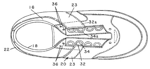
l; Fiy. 2 is a top vie~ of the shoe shown in Fig.
~ ' ~
-4-
.,,
.
, .. :' ~ :~,: ; . '
. .
~2~i33~
~ Fig. 3 is a cu~-away side view of the shoe shown
in ~ig. 1, and lllustrating the anatomical relationship
~etween the bone structure of a foot and the support
member of the invention;
Pig. 4 is a side view of a left shoe of a second
embodiment of the invention, showing the inner side of
the shoe; and
Fig. 5 is a cut-away side vi.ew of the shoe shown
in Fig. 4s illu~trating the anatomical relationship between
lQ the bone struc~ure of a foot and the ~pport member of
the second embodimen~.
DETAII.ED DESCRIPTION OF PREE'ERRED EMBODI~3NTS
Referring to Figs. 1-3, a sports shoe 10 in
accordance with the invention includes a sole 12 and an
upper 16. The. 901e 12 may be formed of polyurethane,
ru~ber or other material. The forward portion of the
sole, corresponding to the ball of the foot, is normally
more flexible than the thicker rear portion, corresp.onding
to the heel. If de ired, the forward portion of the sole
12 may i~clude an insert member 14 of a more wear-resistant
::: material.
`
The upper 16 is preferably formed o~ a relatively
soft, pliable material, such as leather, canvas, or nylon,~
: and may inolude an inside cushiQning liner in a manner
well known~ The upper include~ a foot recei~ing opening
-5-
~ , .
~5332
18, and a pluraLity of lacing eyelets 19 for tying the
shoe around the foot. A rigid stirrup or support member
20 overlie~ the upp~r 16, and includes a pair of ~irst
portions 23, lying on opposite sides of the shoe, and
a second portion 22 that extends between the first portions
23 behind the opening 18, around behind the back of the
shoe.
The first portions 23 of the stirrup member
20 include free upper ends 32, 32a. Each first portion
23 extends downwardly and rearwardly .from its`free upper
end 32 to the rear portion of the sole 12, preferably
joining the sole at a point 24 forward of the calcaneus
bone as described further on. Fig. 1 shows the lower
end of the first portion 23, lying on the inner side of
the shoe and extending from points 24 to 26. This lower
end 24-26 engageq the sole 12 in an area to the rear of
the free uppex end 32 of the first portion. The first
portion lying on the outside part of the shoe may engage
the sole along a complimentary portion lying on the other
2~ : side, but the areas o~ engagement need not be exactly
the same.
: The second portion 22 of the stirrup 20 extends
rearwardly and upwardly from the first portion 23 around
back behind the shoe, and down and forward to the first
2~ portion 23 lying on the outside part cf the upper 16.
As shown in Fig. 3, preferably the rear portion
17 of the shoe upper includes a stiffening member 17a
: that extends from the sole 12 at least to the bottom of
the rear portion 22 of the stirrup 20, such that the
.
-6~
", ~ . ~; ' " ,', . ,~ ' ' '
, ~ '
i33~
~ stirrup rear portion 22 and counter 12a form a unitary
stiff shoe heel portion 17. Also, the stirrup is preferably
at~ached to the upper, for example by stitches 30 along
its outer edges. The upper end 32 of the inside part
of the stirrup includes an eyelet 34, and the upper end
32a of the out~ide part of the stirrup includes a pair
of eyelets 34a. Preferably, the stitching 30 terminates
short of the upper edges, as shawn at 28. The shoe may
be tied by inserting lace~ (not shown~ through the eyelets
19, 34 and 34a of the upper and of the stirrups. Preferably
also, smaller holes 36 are provided ad~acent the ~oot-
receiving opening 18, at the uppex end of the laces. Each
er.d o~ the lace~ may be inserted through one pair of holes
36. When the,lace~ are tied, the holes 36 help prevent
slipping of the lace~ and thereby releasing of the lacing
force. ``
, Fig.. 3 includes a phantom illus~ration of the
bones that lie on the inside portion of the foot 50,
inside a shoe having a support member 20 in accordance
with the in~ention. A lef~ ~oot is shown i~ Fig. 3 and
include the calcaneus or os calcis bone 52, the talus
or astragalus bone 54, the navicular or scaphoid bone
56, the internal:cuniform bone 58, the first metatarsal
: bone 60, and two of the phalanges 62, 64. The tibia bone
25 ~ 66 is also shown in Fig. 3, where it joins the talus bone
54.
: The first portion 23 of the support member 20,
: on the inner side of the foot,: extends over the navicular
bone 56, and has a width roughly equivalent to the area
, , 7
,:,, .
~ , '
3L~ 3~
of the navicular bone 5~ to provide lateral support thereto.
The attachment at points 24, 26 of the first portion Z3
~o the sole 12 acts as an anchor for the stirrup 20, but
as shown, ~he rear portion 22 extends behind the calcaneus
~one 52 such that~ when lateral stress i~ placed on the
foot, the ~tirrup 20 acts to grip the calcaneus and navicular
bones. Thus, support is providPd in a direction between
the navicular bone 56 and the calcaneu~ bone 52, with
the talus bone 54 lying therebetween. The force imparted
involves the sub-talar joint 55 from behind the heel,
in a direc.tion perpendicular to the sub-talar axis, rather
than pulling in the direction of the arch. This structure
provides desirable lateral support for the maiar bones
of the foot.
When a sudden mo~ement is imparted to the foot,
such movement is transmitted to support member 20 which
causes tightening of the laces between eyelets 34. Sideways
movement causes navicular bone 56 and the calcaneus bone
52 to bear against the support member 20 to prevent abnormal
displacement. Force is imparted in a direction perpen~icular
to the sub-talar joint 55.
As a resuIt, a support member 20 in accordance
with the invention pro~ides medio-lateraL stabiLity to
the sub-tala.r joint 55. It inhibits valgus and varus,
i.e. an outward anguIation or an inward angulatio~ of
the foot, by encapsulating the os calcis 52 and talus
54, and inhibits prona~ion, that is, eversion (outward
twisting) and abduction ~inwar~ twistiny) in the tarsal
and metatarsal joints.
: -8-
'` ' ;' ' ~ '~
''"'
. '. ' , ,
~; '; ~ ' ' ~ ' .
~L%~5~3~
~~ The first portion of the stirrup 23 on the
o~tside of the foo~ need not be the shme either in width
or orientatian as that on the inside of the foot. In
the example show~, the first portion is wider on the
outside part of the foot than on the inside. As
discussed above, preferably the first p~rtio~s and second
portion are one piece an~ made of a relatively rigid
plastic ma~erial.
It may be possible to eliminate the outside
1o portion of the support member provided that the rear
portion 2~ that supports the inside first mamber 23 is
con~ected in tension bearin~ relationship to the rear
of the shoe to impart a rearward component of force on
the first member 23, and provided that the upper and 32
can be attached in tension bearin~ engayement with the
outside of the upper, such that force is transmitted in
a direction betwee~ the os calcis 52 and the navicuIar
56 bones.
The sports shae lOa shown in Figs. 4-5 includes
a sole l~a, an upper 16a with a foot-receiving opening
18a, and a ~oe piece 14a~ similar to that shown in Figs.
3.
Th~ shae upper 16a includes an overlay 21a that
extends upwardly from the sole 12a, from a~out midway
:25 of the shoe back behind~the heel portion 17' of the shoe.
The heel portion 17' may include a stiffener or counter
(not shown) similar to ~hat~in Figs. 1-3. ~he overlay
21a may be o~ the same material as the upper, for e~ample
leather or nylon, or may be another:material.
~ ' :
_9_
,.
:
' , .':..... ~' :
.
'. ~
~53312
The suppor~ member 20a, shown for the inside
part of the foot in Figs. 4-5, includes a free upper end
132a, with a means 33a for attaching i~ ~o the other side
of the shoe, in a manner similar to that shown in Figs.
1-3. The reinforcing member 20a includes a first portion
23a that e~tends from the upper and 132a downwardly and
rearwardly, to extend over the navicuIar bone 56. The
lower end 23b of the first portion 23a is attached to
the overlay 21a. Since the overlay 21a is at~ache~ to
the.sole 12a, the upper end 132a of the first portion
23a is thereby in tension.bearing engagemPnt with the
sole 12a.
The second portion 22a of the reinforcin~ member
20a extends upwardly and rearwardly from the lower end
23b of the first portion 23a, and back around t~e rear
portion of the shoe lOa behind the o~ calcis bone 52,
as shawn in Fig. 5. Preferably, the second portion 22a
is stitche~ to the overlay portion 21a, so as to retain
it properly in place~
Althaugh not shown, the portion of the ]uppor~
member 20a on the outside of the shoe look~ generally
the same, i.e. a mirror image of, the inside portion shown
in Fig. 4. A third portion of the support member 20a
~: is dispos~d on the outer side of the sho~ l~a. The Third
portion has a free upper end disposed opposite to the
~ upper end 3Ia, and extend] downwardly and rearwardly from
: its upper end in a manner :similar to portion 23a shown,
to join the opposite side of the second portion 22a. The
upper end of the third por~ion may include an eyelet similar
: 30 to 34a for lacing to eyelet 33a.
.
10--
. . .
. .
:
~ .. . .
.~ .,.
.:
,, :.
~ ~ .
..
: ~ .
~2~332
In the example sh~wn in Fig~. 4-S, the first
portion 23a passes through a guide sLot 31a, but is not
otherwise attached to the upper 16a. The slot 31a act~
to retain the first portion 23a in place, for convenience
in tying ~he shoe. The portion 23a may either ~e rigid,
or may be.slightly resilient, but lacing forces through
the eyelet 34a cause the first portion 23a to bear against
the na~icuIar bone 56 of the foot.
While the support strap 20a does not extend
all the way to the sole it i~ nevertheless attachecl in
tension.bearing relationship to the sole and also behind
the o~ calcis bone of the foot, as is the case in the
embodiment shown in Figs. 1-3. Accordingly, in both
emhodiments of the invention the support stirrup 20 or
20a provides instantaneous and increasing force as motion
tak~es place against the.sides of the foot. The lateral
opposing farce Lmparted by the support member inhibits
angulation of the foot, thereby decrea~in~ momentum and
the amount o work that the correcting muscle structure
: 20 must perform. Because the muscles are no~ overcompensatlng
for foot motion, the support member 20 t 20a in accordance
with the invention decrease. fatigue. It also increases
performance, by reducing the delay in responsiveness of
~ the muscle When changi~g direction, muscles that are
; ~ 25 tensed to overcompensate need to be relaxed and stretched
:~ before other muscIes can move the foot in the desired
direction. Because the muscles will tend to aLready be
relaxed in accordance with the present inven~ion, there
is ~an lmprovement in the responsivenéss of the muscles
~,,
"0:.
.
. .
.
: .: . ,i. . :
... : . .
. ,: : : :
- ., ~: :-
.: ., ; . :. : . .
.:
: ~ . :
' ' . '
~Z~i3~2
and therefare in the time to change direction~. Also,
as discussed above, there is le~s likelihood of injury
to the ankl~ complex and jointc above the sub~talar joints
wh~re the muscles are not attempting to overcompensate
for movement.
The foregoing repre~ent~ a description of a
preferred embodiment of the invention. Variation~ and
modificationc of the structure shown and described herein
will be apparen~ to persons skilled in the art, without
departing from the inventive concepts di~closed herein.
Al1 such modifica~ion~ and variations are intended to
be within the scope of the invention as de~cri~ed in the
following claLms.
-12-
" ,,~,
, . .
.
. :: :
: .: - :
~ ..
,