Note: Descriptions are shown in the official language in which they were submitted.
i3~
BACKGROUND CF THE INVENTION.
This invention concerns high frequency resonators, also known as horns,
mechanical amplitude transfnrmers, concentrators, etc. operating in the
ultrasonic frequency range and used for welding or seaming thermoplastic
workpieces, such as superposed layers of sheet material. More
specifically, this invention refers to the construction of a high
frequency resonator used in conjunction with an apparatus for welding
together layers o~ sheet material instead o~ sewing them. Apparatus used
to vibration weld~ preferably by ultrasonic vibrations, superposed layers
of thermoplastic sheet material in a predetermined pattern are well known
in the art, see for instance U.S. Patent No. 3,733,238 issued to D. D.
Long et al dated May 15, 1973, entitled "Apparatus for Vibration Welding
of Sheet Materialn.
The patent to Long et al explains the need to have an ultrasonic
apparatus constructed to weld the entire width of materials passed
through the apparatus. The problem encountered heretofore was that one
could not construct an array of ultrasonic resonators spanning the entire
width o~ the sheet material without the presence of gaps between the
resona~ors. In order to avoid the gaps, Long et al disclose the use of
two linear arrays of resonators wherein the second row of resonators
lls the gaps of the first row of resonators. An arrangement for
avoiding~the need for two rows of resonators and using a single array of
resonators is shown in V.S. Patent No. 4,246,416 issued to H.S. Goldman
dated March 27, 1979 entitled "Apparatus for Vibration Welding o~
Material". This patent discloses blade-shaped resonators 6~ a suitable
configuration ~or causing two juxtaposed resonators to have interfacing
surfaces. For instance, thls patent shows resonators of trapezoidal and
"T"-shaped cross-section to provide for interfacial relationships between
laterally ~uxtaposed resonator surfaces in order to pre~vent the existence
of gaps when passing sheet material through the apparatu~;.
- 2 --
3~
Resonators of the last mentloned oonstructlon have a ser$ous shortcoming
~n that the sesonators are dynamlcally unbalanced about the lateral
axis. Fo~ces ~enerated by the acceleration oP an unbalanced resonator
mass provide a couple which produ~es ~lexure motlon thereby stimulating
undesired ~lexural resonanoes~ This phenomenon presents a serious
problem in h~gh gain blade-shaped resonato~s which ar`e driven at a high
~echanical amplitude, The undesirable mechanical stress condltion
resulting trom the unbalanced resonator causes ~ailure of the acoustlcal
components Or the apparatus.
~U~ w.
The present ~nvention discloses a resonator construction which overcomes
the above stated shortcomings. A blade-shaped high frequency resonator
ls revealed whlch is prov$ded at its output surtace with lateral~y
extending ears. The ears have.end surfaces which interface wlth similar
end surtaces Or a ~uxtaposed resonator. For instance, the end surraces
are ~ a zLgzag can~i~uration whlch is matched by thP end surtaGes ot a
~uxtaposed resonator, Most impo~tantly, however, the ears are
constructed to cause th~ su~ of the moments about the oentrally dispo~aed
lateral resonator axis to be substantlally zero. Expressed otherwise,
khe ears are eonstructed to cause the mo~ents about the lateral resonator
axis on one side to ~e substantlally equal to the moments on the other
slde D~' the ax~c~ t~reby erfectin~ a balar~e of the mornents,
:
Thus, tha ln~ren~ion provides a new and improved high f requency
re60nator use~ul in an ul~raRonic welding a~paratu~ ~or ~heet
mater ia l .
: ~
The pre~ent invention further pLovides in one a pect a new and
improved blade-~haped rssonator adapted to operate in the
ultrasonic ~requency range having laterally extending ears with
-- 3 --
A
3~
end sur~ace~ const~ucted for providing an inte~facing ~lation6hip
with the end sur~aces of a similarly constructed juxtaposed
resonato~ and the ear~ being constructed ~o provide balanced
mechanical moment~ about the lateral axi6 of the resonator.
The presant invention al80 provide~ in a preferred aspect a new
and impYoved blade-shaped resonator ~or ultrasonic welding having
laterally extending ears at the output ~ur~ace with laterally
protruding e~d sur~aces of zigzag configuration for providing an
interfacing eelation~hip with a fiimilarly constructed resonator in
juxtaposed po6ition, and the ears being con6truc~ed to cau~e the
$um of the moments about the centrally disposed lateral axis of
the ~e~onato~ to be sub6tantially zero.
Other and still ~u~ther advantages of this invention will be more
clearly apparent by ~eEe~once to the following description when
taken in con~un~tion with the accompanying d~awings.
BRIEF DESCRIPTION OF ~HE DRAWINGS.
_____~___
FIGURE 1 ~s an elevational view deplctino an ultrasonlc weldln~
apparatus tor sh~et material comprisirg a roller and an array
:o~ sources or v~bratory energy;
FIGURE 2 is a plan view showing thc cross sectlon of high ~requency
: ~ resonators as proposed $n the prior art;
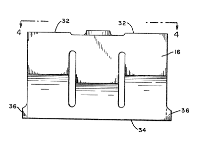
; ~ : FIGURE 3 is a~slde eleva~lonal vlew of the hlgh ~requency resonatorconstru~ted ln acco~dance with the present in~ention;
FIEURE 4 is~a top plan v~ew ot the th@ new and lmproved resonator per
Fi~ure 3;
3~
FIGURE 5 is an elevational end view of the new resonator shown in
Figure 3,
FIGURE 6 is an explanatory illustration, and
FIGURE 7 is a view illustrating the intertacing relationship o~
resonator end surfaces when resonators are disposed in
juxtaposed relation.
DETAILED DESCRIPTION OF THE INVENTION.
Referring now to the figures and Figure 1 in particular, there is shown a
high frequency vibxatory welding or sealing apparatus 10 comprising a
rotatably mounted roller 12 provided along its surface with a pattern o~
raised welding surfaces in the form o~ raised pins 14, see Long et al.
An array o~ juxtaposed high ~requency resonators 16~is disposed to~face
the roller 12 and forms with the roller a nip through~which sheet
material 18 to be welded lS fed. Each resonator 16 is mechanically
coupled to an electroacoustic converter 20 which receives electrical high
frequency ~nergy ~rom a suitable source, not shown, and provides high
frequency mechanical vibrations to the input surface 22 o~ the associated
resonator to cause the~opposltely disposed output sur~ace 24 of the
resonator to~transmit;ampli~ied~high fre~uency v1brations to the sheee
material 18. As a result, sheet material passed through~the nip is~
welded ~n~accordance~with~the pattern 14 on the~roller 12. As will be
noted,~there~is a sirg1e row~of~resonators 16 and~in order to 1eave no
gap, that is~a not-we1ded~portion~in the sheet~material 18 as it ls~fed
through~the nip which is~the~welding station, it has been proposed to~use
resonator cross-sectlons which cause juxtapossd latsral faces o~ the
resonators to be in an interracing relationship. Figure 2 shows the
cross sections proposed in Soldman supra. Figure~2a shows a trap~ezoidal
cross-section ~or the resonator, Figure 2b shows a rectangular
cross-section resonator w1th upper and lower extensions, Figure 2c shows
- S - :
:
6~3~;~
"Tn-shaped cross-sections, and Figure 2d shows parallelogram
cross-sections. In each instance, the resonators are arranged in a
single row or with interfacing lateral end surfaces when viewed in the
direction along which the sheet material passes through the nip be~ween
the roller and resonators.
However, as illustrated in Figure 2, resonators constructed in accordance
with these designs are afflicted with a severe shortcoming n that the
resonators are dynamically unbalanced, which condition causes the
existence o~ highly undesirable flexural modes of vibration, Such
vibrations, due to the high acceleration ~orces and mechanical gain at
which resonators of this type operate, cause such an unbalance to be a
serious problem, leading to unnecessary stress and failure of the
resonator itself as well as ~ailure of the associated converter ZOO The
unbalanced condition iS depicted schematically in Figure 2 where the
lateral resonator axis has been drawn and designated by numeral 26. The
resonator cross-section portion above and below the lateral resonator
axis 26 has been indicated by cross-hatching and it will be noted that -
there exists a significant imbalance which causes the generation of
flexural vibrations,
As used herein "lateral axis" of the resonator shall be de~ined as an
axis dispased normal to the longitudinal axis 27 (Figure 5) ot the
resonator and~disposed centrally with respec~ to the large side surfaces
28 and 30 or 28' and 30' of the resonator, see Figures 2 and 4.
The heretofore existing problem has been overcome by a reso~natnr
construction shown in Figures 3, 4 and 5. The resonator 16 basically is
a blade-shaped resonator as illustrated and described in U.S. Patent No.
4,651,04~ issued to E. A. Harris et al, dated March 17, 1987 entltled
~Resonator Exhabiting Uni~orm Motianal Outputn, see Figure 2 o~ the
patent. The resonator is dimensioned to cause it to be resonant as a
half wavele~gth resonator for high frequency vibrations of predetermined
frequency apolied at the input sur~ace 32 and travelin3 longitudinally
therethrough to the oppositely disposed output surface ~4 which transmits
the vibration to the material in ~orced contact therewith. Under this
condition, the inout surface 32 and output surface 34 are disposed at
antinodal regions of longitudinal vibration. In a typical example, the
resonator is dimensioned to be resonant at a ~requency o~ 20 kHz.
However, the resonator may be dimensioned tD be resonant at any other
suitable high frequency, typically a frequency in the range between 16
kH~ and 100 kHz.
The improvement in the resonator construction disclosed herein resides in
the construction o~ the ears 36 extending laterally from the output
surface 34.
Importantly, the ears are dimensioned to cause the sum of the moments
relative to ~he lateral reso~ator axis 26 to be substantially zero, that
is, the ~um of the mass Lncrements times the distance from the lateral ;
axis 26 is substantially zero. Expressed otherwise, the moments, above
the axis 26 are equal to the moments below th axi`s 26, see Figure 6.
Thus, a balanked dynamic condition is achieved, thereby avoiding the
generation o~ the undesired flexural~ resonances. ~
Figure 7 shows the interfacing relationship of juxtaposed resonators 16,
ths resonators being arranged in a sin31e row.~ The juxtaposed lateral
end surfaces 38 of the ear ~6 of the resonator 16A and those o~the
resonator 16B are disposed in an interfacing relationship~ As sheet
,
material to be welded is passed underneath the resonatnr in the direction
of arrow 40 through the nip between the roller 12 and the resonators 16A
and 16B, all portions o~ the sheet ma~erial are welded, without leaving a
gap.
.'
::~265i36;~ 1
When using an apparatus as shown in Figure 1, namely a roller and an
array of resonators, welding of the sheet materia:L GCCUrS along a line,
substantially at a line coincident with the lateral resonator axis 26.
In order to effect welding without leaving a gap, it is important that
the respective end surface 38 of the resonator intersect the lateral axis
26 of the resonator at an angle o~ less than 90 degrees. The pre~erred
range is an angle between 30 and 60 degrees, see Figure 7. This
requirement essentially causes She lateral end surfaces to exhibit a
zigzag pattern~ Moreover, as shown the resonators are dimensioned to
have a symmetrical pattern for causing each resonator to be in
interfacing relationship with another resonator constructed similarly.
While there has been described and illustrated a preferred embDdimen$ o~
the Lnvention, it will be apparent to those skilled in the a~t that
~ ~ ~ various changes and modifications may be made without departing from the;
J broad princ-ple of this invention whlch shall be limited only by the
~: :
scnpe of the appended claims.
What is claimed is:
; . : : -
:
., . ~