Language selection

Search

Patent 1265491 Summary

Third-party information liability

Some of the information on this Web page has been provided by external sources. The Government of Canada is not responsible for the accuracy, reliability or currency of the information supplied by external sources. Users wishing to rely upon this information should consult directly with the source of the information. Content provided by external sources is not subject to official languages, privacy and accessibility requirements.

Claims and Abstract availability

Any discrepancies in the text and image of the Claims and Abstract are due to differing posting times. Text of the Claims and Abstract are posted:

  • At the time the application is open to public inspection;
  • At the time of issue of the patent (grant).
(12) Patent: (11) CA 1265491
(21) Application Number: 481941
(54) English Title: METALLIC RAILWAY SLEEPERS WITH CORRUGATED ENDS
(54) French Title: TRAVERSES METALLIQUES A BOUTS ONDULES POUR VOIES FERREES
Status: Deemed expired
Bibliographic Data
(52) Canadian Patent Classification (CPC):
  • 238/41
(51) International Patent Classification (IPC):
  • E01B 3/16 (2006.01)
(72) Inventors :
  • HODGSON, WILLIAM H. (United Kingdom)
(73) Owners :
  • HODGSON, WILLIAM H. (Not Available)
  • BRITISH STEEL PLC (United Kingdom)
(71) Applicants :
(74) Agent: ROBIC, ROBIC & ASSOCIES/ASSOCIATES
(74) Associate agent:
(45) Issued: 1990-02-06
(22) Filed Date: 1985-05-21
Availability of licence: N/A
(25) Language of filing: English

Patent Cooperation Treaty (PCT): No

(30) Application Priority Data:
Application No. Country/Territory Date
84 13333 United Kingdom 1984-05-24

Abstracts

English Abstract


METALLIC RAILWAY SLEEPER WITH CORRUGATED ENDS


ABSTRACT OF THE DISCLOSURE:

There is provided a railway sleeper having a
formed inverted rolled steel channel-shaped section the ends
of which have their upper surfaces downwardly inclined and
inwardly tapered over their central region towards the
sleeper extremities so as to progressively define at these
extremities, in end elevation, a serpentine path having
downwardly inclined portions at the side and two further
such portions inwardly thereof. The ends of the channel-
shaped section are press formed and of improved strength and
rigidty. The sleeper is of consistent with and continuous
form along its entire length.


Claims

Note: Claims are shown in the official language in which they were submitted.


The embodiments of the invention in which an
exclusive property or privilege is claimed are defined as
follows:

1. A railway sleeper having an inverted rolled s
teel channel-shaped section the ends of which have their
upper surfaces downwardly inclined and inwardly tapered over
their central region towards the sleeper extremities
whereby to define at said extremities a corrugated contour
to add s trength and rigidity to the sleeper, said ends
being press formed, the sleeper being of consistent width
and continuous form along its entire length.

2. A railway sleeper having a formed inverted
rolled steel channel-shaped section the ends of which have
their upper surfaces downwardly inclined and inwardly
tapered over their central region towards the sleeper
extremities so as to progressively define at said
extremities, in end elevation, a serpentine path having
downwardly inclined portions at the side and two further
such portions inwardly thereof, said ends being press
formed, the sleeper being of consistent width and continuous
form along its entire length.

3. A sleeper according to claim 2, wherein the
width across the bottom of the inverted section is
consistent along its whole length including the bottom of
the said downwardly inclined side portions at the ends, the
underside of the inverted section being flat over its whole
length.

4. A sleeper according to claim 3, wherein the
serpentine shape of each said end is symmetrical, a U-shaped
depression lying centrally thereof.


5. A sleeper according to claim 4, wherein the
section is roll-formed steel, the ends being press-formed.

6. A sleeper according to claim 5, designed so as
to be stackable with other identical sleepers, one nesting
within the other.

7. A roll formed steel railway sleeper having an
inverted channel-shaped section and press formed ends having
their upper surfaces downwardly inclined and inwardly
tapered over their central region towards the sleeper
extremities so as to pregressively define at said
extremities, in end elevation, a serpentine path having
downwardly inclined portions at the side and two further
such portions inwardly thereof defining a U-shaped central
depression, and each sleeper being of consistent width and
continuous form along its entire length.

8. A sleeper according to claim 7, wherein the
width across the bottom of the inverted section is
consistent along its whole length including the bottom of
said downwardly inclined side portions at the ends, the
underside of the inverted section being flat over its whole
length.

9. A sleeper according to claim 8, comprising two
rail base plates secured to its upper surface.


Description

Note: Descriptions are shown in the official language in which they were submitted.


~ltS5~

-- 1 --

This invention rela-tes to railway sleepers, and
more particularly relates -to channel-section rne-tal sleepers
having downwardly inclined 'spade~ ends.
Conventional spade end sleepers which have their
plain upper surfaces downwardly inclined at an angle of
between say 40 and up to 90 -to the horizontal suffer from
the drawback tha-t loads cannot readily be substained closely
adjacent these ends, because they 'dig in' to the ballast in
response to sideways movement, they cannot be readily
replaced for maintenance purposes etc. and with steep angled
ends they do not readily stack.
It is an object of this invention to provide an
improved sleeper which mitigates the above problems.
According to the invention there is provided a
railway sleeper having a formed inverted channel-shaped
section the ends of which have their upper surfaces
downwardly inclined and inwardly tapered over their central
region towards the sleeper extremities whereby to define at
these extremities a corrugated contour to add strength and
rigidity to the sleeper, these ends being press formed, the
sleeper being of consistent width and continuous form along
its entire length.
According to the invention there is further
provided a railway sleeper having a formed inverted channel-
shaped section the ends of which have their upper surfaces
downwardly inclined and inwardly tapered over their central
region towards the sleeper extremities so as to
progressively define at said extremities, in end elevation,
a serpentine path having downwardly inclined portins at the
side and two further such portions inwardly thereof, these
ends being press formed, the sleeper being of consistent
width and continuous form along its entire leng-th.
Preferably, the width across the bottom of the
inverted section is consistent along its whole leng-th
''


- la -

including the bottom of -the downwardly inclined side
portions at the ends, -the underside of the invert~d section
being flat over i-ts whole leng-th. Pre~erabl again, the
serpentine shape o~ each end is symmetrical, a U-shaped
depression lying centrally -thereo~.
The 'dished spade' end contour of the sleeper may
be pressed from a standard rolled steel channel section. By
virtue of the stron~er ends thus produced these portions can
sustain a greater
;


~`


load than the con~entional design hitherto - this means that the
length of the sleeper according to thi~ invention may be much
shorter, e.g. 2C% less than the conventional design for the æame
load bearing capacity, representing a conæiderable coæt æaving.
~he shape facilities stacking, and lateral insertion beneath
the track for track maintenance and replacement etc., and although
the end design i8 such that it affords less restraint against
lateral load thrustæ it is still 5~/0 or flO greater than the
standard concrete or wooden æleeper.


In order that the invention may be ~ully understood one embodiment
thereof will now be described with reference to the ac¢om-panying
drawings in which


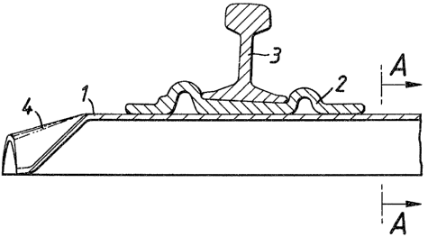
Figure 1 is a longitudinal section on the centre line of a
æleeper according to the invention;
Figure 2 iS a plan view of the sleeper of ~igure 1 (without
the rail);
~igure 3 is a section on A-A in the above Figureæ; and
Figure 4 is an end elevation of Figure 2


Referring now to Figure 1 and 2 in the drawings a steel ~leeper 1
haæ~welded to it a rolled steel base plate 2 whi¢h in the example
shown has an inwardly sloping upper ~urfaoe suoh as to support a
r il 3 in a tilted fa~hion. lhe body of the sleeper is roll formed

and then the end is press formed in a manner suoh that the upper
surfaoe 4 is inolined downwardly and BO shaped as to progressively
define at itB extremity a ~erpentine or sinuous configuration.


~65~
", . ~,~

Thi~ i8 better illustrated in Figure 4 where it can be seen
that it approximates to an undulating path extending over 1~ cycles.
me sides each have upwardly inclined surfaces 5, 6 merging into
a ~-shaped central section havir~ downwardly inclined surfaces 7,8.


Four 'upright' portions are thus manifested by this form of
construction significantly strengthening the 31eeper ends giving
rise to the advantages claimed above.


To give practical example on the above, with a 1435mm track
gauge, the overall sleeper length may be 2,300mm, the a~-rolled
section (~ig.3) with side wall thickness of 6.75mm may have a
weight of 27 kg/metre with the total weight of the sleeper as
pressed in the normal indu6trial sleeper grade steel being 62 kg.


Although thé invention has been described with reference to
the particular embodiment illustrated, it is to be understood that
various modifications may readily be made without departing from
the soope of this invention. For example, the precise ~hape and
size of the ~trengthened 'corrugated' ends may differ from that
shown compatible with the objects as recited above.


.
Representative Drawing
A single figure which represents the drawing illustrating the invention.
Administrative Status

For a clearer understanding of the status of the application/patent presented on this page, the site Disclaimer , as well as the definitions for Patent , Administrative Status , Maintenance Fee  and Payment History  should be consulted.

Administrative Status

Title Date
Forecasted Issue Date 1990-02-06
(22) Filed 1985-05-21
(45) Issued 1990-02-06
Deemed Expired 1992-08-08

Abandonment History

There is no abandonment history.

Payment History

Fee Type Anniversary Year Due Date Amount Paid Paid Date
Application Fee $0.00 1985-05-21
Registration of a document - section 124 $0.00 1985-08-07
Registration of a document - section 124 $0.00 1989-05-11
Owners on Record

Note: Records showing the ownership history in alphabetical order.

Current Owners on Record
HODGSON, WILLIAM H.
BRITISH STEEL PLC
Past Owners on Record
BRITISH STEEL CORPORATION
Past Owners that do not appear in the "Owners on Record" listing will appear in other documentation within the application.
Documents

To view selected files, please enter reCAPTCHA code :


To view images, click a link in the Document Description column. To download the documents, select one or more checkboxes in the first column and then click the "Download Selected in PDF format (Zip Archive)" or the "Download Selected as Single PDF" button.

List of published and non-published patent-specific documents on the CPD .

If you have any difficulty accessing content, you can call the Client Service Centre at 1-866-997-1936 or send them an e-mail at CIPO Client Service Centre.


Document
Description 
Date
(yyyy-mm-dd) 
Number of pages   Size of Image (KB) 
Representative Drawing 2001-11-14 1 9
Drawings 1993-09-15 2 57
Claims 1993-09-15 2 70
Abstract 1993-09-15 1 20
Cover Page 1993-09-15 1 16
Description 1993-09-15 4 132