Language selection

Search

Patent 1265547 Summary

Third-party information liability

Some of the information on this Web page has been provided by external sources. The Government of Canada is not responsible for the accuracy, reliability or currency of the information supplied by external sources. Users wishing to rely upon this information should consult directly with the source of the information. Content provided by external sources is not subject to official languages, privacy and accessibility requirements.

Claims and Abstract availability

Any discrepancies in the text and image of the Claims and Abstract are due to differing posting times. Text of the Claims and Abstract are posted:

  • At the time the application is open to public inspection;
  • At the time of issue of the patent (grant).
(12) Patent: (11) CA 1265547
(21) Application Number: 489217
(54) English Title: RING SEALS
(54) French Title: BAGUE D'ETANCHEITE
Status: Deemed expired
Bibliographic Data
(52) Canadian Patent Classification (CPC):
  • 277/49
  • 277/57
  • 277/66
(51) International Patent Classification (IPC):
  • F16J 15/12 (2006.01)
  • F16J 15/32 (2006.01)
(72) Inventors :
  • NICHOLSON, TERENCE PETER (United Kingdom)
(73) Owners :
  • NICHOLSON, TERENCE PETER (Not Available)
(71) Applicants :
(74) Agent: MARKS & CLERK
(74) Associate agent:
(45) Issued: 1990-02-06
(22) Filed Date: 1985-08-22
Availability of licence: N/A
(25) Language of filing: English

Patent Cooperation Treaty (PCT): No

(30) Application Priority Data:
Application No. Country/Territory Date
8421326 United Kingdom 1984-08-22

Abstracts

English Abstract


ABSTRACT

A ring seal of the kind comprising an annular jacket
of relatively yieldable material with a channel
containing an energising spring to impart resilience
thereto, is characterised in that the channel is of
substantially part-elliptical profile and contains a
partly spaced spring ring of channel shaped radial
profile. The spring ring comprises a pair of metal
rings which have axial slits and are secured
together around their outer periphery prior to insertion
in the jacket channel. Additionally the spring ring may
have a plane circular ring welded thereto in a central
diametric plane and to this latter ring there may be
secured a dual component cylindrical protection ring
having its axis coincident with the axis of the ring
seal.


Claims

Note: Claims are shown in the official language in which they were submitted.


THE EMBODIMENTS OF THE INVENTION IN WHICH AN EXCLUSIVE
PROPERTY OR PRIVILEGE IS CLAIMED ARE DEFINED AS FOLLOWS:

1. A ring seal characterized in that a channel in the
annular jacket is of substantially part-elliptical radial profile
and contains a partly spaced spring ring of partly elliptical
radial profile comprised of a pair of metal rings which have
axial slits and are secured together around their outer periphery
prior to insertion within the jacket.

2. A ring seal as claimed in claim 1 in which the
spring ring has a plane circular ring situated in a central
diametric plane secured thereto.

3. A ring seal as claimed in claim 2 in which there is
secured to the plane circular ring at its radially inner part a
dual component cylindrical protection ring having its axis
coincident with the axis of the ring seal.


Description

Note: Descriptions are shown in the official language in which they were submitted.


1~65547


"IMPROVEMENTS RELATING TO RING SEALS"


This invention relates to ring seals of the kind
comprising an annular jacket of relatively yieldable
material which is of channel shaped radial cross-section
and to which resilience is imparted by an internal
energising spring ring which is located in the channel.
The jacket may be made of material having a low friction
co-efficient such as Teflon (Registered Trade Mark).
The spring may be made of either metal or elastomer in
various configuration~. It may thus be of helically
coiled construction or of channel shaped radial
cross-section. In our ~ patent a~Uk.~u~
no. ~s~9 there is proposed a ring seal of the kind
referred to for static sealing purposes.

Such ring seal6 may be used as static seals, that is
to say for sealing between two static mating face~ or as
dynamic seals that is to say for ~ealing, externally or
internally, reciprocating or rotating shafts in relation
to adjacent tubes, casings or the like.
The present invention is concerned however with
dynamic ring sealing and has been devised with the
object of providing an inproved dynamic ring seal of the
kind referred to which is less liable to failure by
metal spring fatigue or dislodgement of the spring from
the jacket.


~265547

Some tyyical embodiments of the invention are
illustrated in the accompanying drawings and will
hereinafter be described.
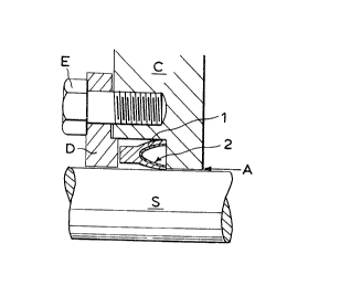
In these drawings:
Figs. l to g inclusive are fragmentary sectional
views which respectively show the Eour different
embodiments in a typical working environment;
Figs. 5. 6 and 7 are radial sections of energising
spring rings which Iespectively form ~art of the
sealing rings illustrated in Figs. l to 3;
Fig. 8 is a diametric section through an energising
spring ring showing its mode of construction; and
Fig. 9 is a side elevation of the energising spring
ring a~ shown in Fig. 8.
~5 In each of Figs. l to ~ inclusive there is shown a
rotating or reciprocating shaft F which projects
rotating end wall C. This end wall has an annular
cavity which accommodates the sealing ring and the
sealing ring is held in place by an annulus D which is
tightened on to the casing wall C by means of a stud E.
In each instance the sealing ring comprises an outer
machined jacket made of relatively yieldable,
low-friction material such as Teflon (Registered Trade
Mark). The jacket has a channel of substant;ally
semi-elliptical radial profile which accommodates an
energising sering which is also of substantially
semi-elliptical radial profile. The spring is made of


~265547


any suitable resilient material such as phosphor bronze,
,~ ~
spring steel, stainless steel or Inconel~or Nimonic high
nickel alloys, depending upon the intended operational
environment. Further, as indicated in each of Figs. 5,
6 and 7 each spring ring comprises an inner ring
component 2a and an outer ring component 2b which are
united by welding 3. Further, as shown in Fig. 8, the
inside wall of the spring is formed with a seIies of
parallel slits 2c which terminate in triangular shaped
openings. The outside wall of the spring is also formed
with similar slits 2d, as shown in Fig. 9, but the slits
2d are wider than the slits 2c because the latter opens
slightly due to exeansion of the ring when it is fitted
whereas the slits 2d have to allow for the reduction in
overall diameter which occurs when the rinq is fitted
into the jacket.
In Fig. l the sealing ring is resisting a static
pressure applied in the direction of the arrow A and the
sealing ring has the simple construction illustrated in
Fig. 5. In Fig. 2 however the sealing ring is resisting
a pumping pressure B and has the form illustrated in
Fig. 6, that is to say it has centrally welded thereto a

plane circular ring 4. This circular ring prevents the
sealing ring as a whole from being drawn backwards and
forwards into this recess when the shaft reciprocates.
The arrangement illustrated in Fig. 3 is
specifically intended to protect the recess in which the


~Z65S47


located f~om forei(~n
flow in the direction îndicated by the arrow M- Thus as

Fig 7 there is attaChe
mpOnent protection ring
i dicated in Fig- 4- and
inst alternatin9 pressU
0 there is fitted back t
in the caSing C twO se
i d in reference to Fig- 2

it is to be unde~Stoo
0nditions there will n

between the oUter sUr
h inner surfaCe of the

h foregoing described e
itself remains bOdily
understood that the sealing ring may be used in or in
i n with a moving compon
tance~ a ~iston-

ed the sealing ring j

r0vide~ at the entranC
lip6 which would p~oje
i ring to prevent all ~oS
latter being outwardly dislodged-
~ing rings could be ele

d with Some loW-friction
pa~tiCUlar envi~nment

~Z~i5547


One of the main advantages of making the spring from
two pieces of metal is that metal of different
thicknesses can be used for the components, thus varying
the characteristics of the sealing ring as a whole. For
instance if the sealing ring is sealing on a stationary
outer element and a rotating centre shaft, the outer
part of the spring may be produced from thicker material
which results not only in greater sealing capability but
also prevents the seal from rotating in its housing, and
vice versa if the element was rotating and the shaft wa6
stationary.

Representative Drawing
A single figure which represents the drawing illustrating the invention.
Administrative Status

For a clearer understanding of the status of the application/patent presented on this page, the site Disclaimer , as well as the definitions for Patent , Administrative Status , Maintenance Fee  and Payment History  should be consulted.

Administrative Status

Title Date
Forecasted Issue Date 1990-02-06
(22) Filed 1985-08-22
(45) Issued 1990-02-06
Deemed Expired 1998-02-06

Abandonment History

There is no abandonment history.

Payment History

Fee Type Anniversary Year Due Date Amount Paid Paid Date
Application Fee $0.00 1985-08-22
Maintenance Fee - Patent - Old Act 2 1992-02-06 $100.00 1992-01-13
Maintenance Fee - Patent - Old Act 3 1993-02-08 $100.00 1992-12-14
Maintenance Fee - Patent - Old Act 4 1994-02-07 $100.00 1994-01-17
Maintenance Fee - Patent - Old Act 5 1995-02-06 $150.00 1995-01-19
Maintenance Fee - Patent - Old Act 6 1996-02-06 $150.00 1996-01-18
Owners on Record

Note: Records showing the ownership history in alphabetical order.

Current Owners on Record
NICHOLSON, TERENCE PETER
Past Owners on Record
None
Past Owners that do not appear in the "Owners on Record" listing will appear in other documentation within the application.
Documents

To view selected files, please enter reCAPTCHA code :


To view images, click a link in the Document Description column. To download the documents, select one or more checkboxes in the first column and then click the "Download Selected in PDF format (Zip Archive)" or the "Download Selected as Single PDF" button.

List of published and non-published patent-specific documents on the CPD .

If you have any difficulty accessing content, you can call the Client Service Centre at 1-866-997-1936 or send them an e-mail at CIPO Client Service Centre.


Document
Description 
Date
(yyyy-mm-dd) 
Number of pages   Size of Image (KB) 
Representative Drawing 2001-07-03 1 6
Drawings 1993-11-23 2 45
Claims 1993-11-23 1 24
Abstract 1993-11-23 1 20
Cover Page 1993-11-23 1 14
Description 1993-11-23 5 145
Fees 1992-01-13 1 62
Fees 1992-12-14 1 60
Fees 1994-01-17 1 64
Fees 1995-01-19 1 69
Fees 1996-01-18 1 71