Note: Descriptions are shown in the official language in which they were submitted.
~2~5~6
MET~OD OF MANUFACTURe ~F AN ~LECTRICAL
TERMINAL ON ~N INJECTION MOLDING NOZZLX
BACKGROUND OF THE INVENTION
1 This invention relates generally to injection
molding and more particularly to a method of making an
injection molding nozzle with an improved terminal for the
integral electric heating element.
Integral electric heating elements have a small
diameter resistance wire which connects to a larger
diameter conductor to provide a terminal to which the
external~electrical lead is connected. While the
resistance wire of the heating element is electrically
~connected to the terminal, it must be electrically
insulated from:the noz~le along its length to avoicl
1 5 ~ ~ ~
:
. . .
~2~59~
1 grounding. This must be accomp~ished w;~ile providing the
terminal with sufficient structural strength to withstand
failure due to torquing when the lead wlre is connected or
disconnected.
Injection molding nozzles having integral
heating elements are well known in the art. The
applicant~s U.S. patent number 4,768,283 discloses a
method which provides a protective nickel coating over the
heating element which is integrally embedded in a spiral
channel. The Canadian patent application serial number
549,517 entitled ~Meth,od of Manufacture of Injection
Molding Nozzle having Grounded Heating Element Brazed into
Pointed Tip~, filed October 16, 1987 by Jobst Uleich
Gellert and U.S. patent number 4,768,94; to Schmidt et al.
15 which issued September 6, 1988 discloses grounding the
heating element at the forward end of the pointed tip of
the nozzle.
A variety of different terminal arrangements are
also known in the art. For instance, the applicant~s U.S.
20 patent numbers 4,403,405 which issued September 13, 1983
and 4,446,360 (divisional~ show a nozzle and method of
maklng lt~having a terminal protected by a connector
sleeve~with sealing provided by a split washer assembly.
Further developments are shown in the applicant~s U.S.
25 patent numbers 4,557,685 and 4,583,284 (divisional) which
:
.
~: . ,, .
.
. , . . : ,. .:
. - . .~ . :
~- .. '
_ 3 ~
1 issued April 22, 1986. More recently, the applicant s
Canadian patent application serial number 549,520 entitled
Method of Manufacture of Injection Molding Nozzle
Electrical Terminal which was filed on October 16, 1987,
discloses a method of making a nozzle with a terminal by
connecting the rear end of the heating element to a stud
and pouring molten insulating material around it. While
all of these methods represented considerable improvements
at the time, they have the disadvantages that a
considerable number of steps are required to make the
nozzle and the terminals do not have sufficient structural
strength to prevent failure due to torque from the
external lead being connected and disconnected.
SUMMARY OF THE INVENTION
Accordlngly, it is an object of the present
invention to at least partially overcome the disadvantages
~ of the prior art by providing an efficient method of
:` making an integral injection molding nozzle which
electrically insulates the términal from the nozzle body
while providing~;sufficient structurll strength to
withstand torque from the external le2d being connected
and disconnected,
~ To thls end, in one of lts aspects, the
invention provides a method of making an integral
:: ~
. ~ ~
:` :
" : :
,. ~ ,
~Z65~6
1 elongated heated injection molding nozzle with a Eorward
end and a rear end to be seated in a well in a cooled mold
with minimal contact bridging an insulative air space
provided between the heated nozzle and the surrounding
cooled mold, the nozzle having a melt bore extending
therethrough from a central inlet at the rear end to
convey pressurized melt received at the inlet towards at
least one gate extending from the well to a cavity in the
mold, the nozzle having a steel main body portion with a
generally cylindrical outer surface extending from a steel
collar portion adjacent the rear end, the method including
the steps of integrally vacuum brazing the nozzle together
with a portion of an electrical heating element brazed in
a spiral channel extending around the cylindrical outer
surface of the main body portion, the heating element
having a resistance wire extending through an electrical
insulating material in an outer casing and a rear end
extending out through a radial opening in the collar
portion to a terminal, with the improvement including
forming a plug having a front face, an outer surface and a
heating element bore extending therethrough and seating
the plug in the radial opening in the collar portion by
inserting the rear end of the heating element into the
bore and sliding the plug to a position where it is seated
in the ra~ial opening with a rear end portion of the
: ' ~'' :,
~. : '
;s~
1 heating element projecting at least a predetermined
minimum distance from the front face of the plug, forming
a terminal body with a heating element bore extending
centrally therethrough from a rear end to a front end, the
terminal body having a front portion with a threaded outer
surface adjacent the front end and a rear portion with an
outer surface adjacent the rear end, stripping the outer
casing and insulating material from the heating element to
expose the resistance wire for a short distance adjacent
the rear end, surrounding the casing of the rear end
portion of the heating element projecting from the front
face of the plug with insulating material and applying a
thin coating of insulating material to the outer surface
of the rear portion of the terminal body, forming a
protective cap having an inner surface which matches the
outer surface of the rear portion of the terminal body and
an outer surface which matches the front surface of the
plug, mountlng the protective cap on the rear portion of
the terminal body in position to protect the coating of
insulating material and pressing the protective cap in
place to prevent relative rotation between the cap and the
terminal body, mounting the terminal body and the
protectlve cap on the nozzle by inserting the rear end of
the heating element into the heating element bore
therethrough and sliding the terminal portion to a
` ~ :
.. . ~
~ .
- 6 -
1 position wherein the outer surface of tne protective cap
abuts against the front face of the plug and securing the
terminal body and the protective cap in that position, and
electrically connecting the exposed resistance wire of the
heating element adjacent the rear end to the front portion
of the terminal body.
Further objects and advantages of the invention
will appear from the following description taken together
with the accompanying drawings.
BRIEF DESCRIPTION OF THE DRAWINGS
Figure 1 is a sectional view of a portion of a
multi-cavity injection molding system showing a nozzle
having a terminal made according to a preferred embodiment
of the invention,
Figures 2 - 7 show the sequence of steps in
making the nozzle with the terminal according to one
embodiment of the invention, and
Figure 8 shows a batch of assembled nozzles to
be inserted in a vacuum furnace to secure the terminal
according to another embodiment of the invention.
: ~ ,
- .
: .
., ~ . .
~26~ 6
DETAILED DESCRIPTION OF THE DRAWINGS
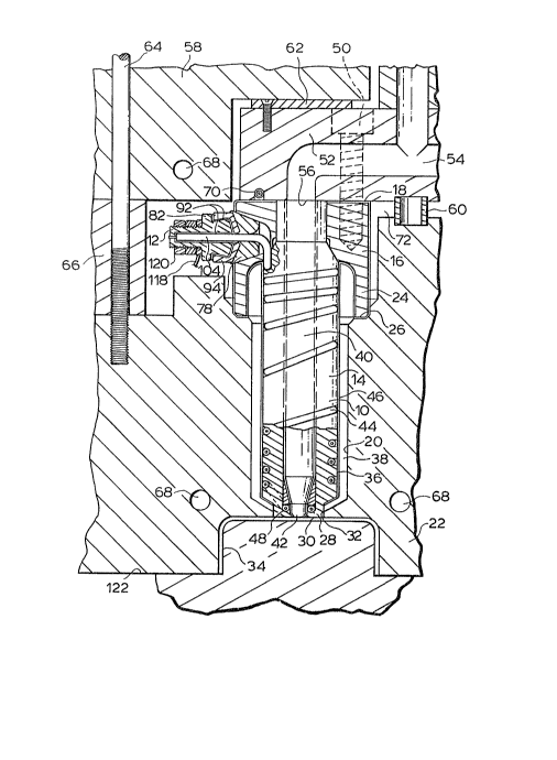
1 Reference is first made to Figure 1 which shows
a portion of a sprue gated injection molding system having
a number of heated nozzles 10 with an electrical terminal
12 made according to a preferred embodiment of the
invention. Each nozzle 10 has a steel main body portion
14 extending from a steel collar portion 16 adjacent the
back end 18. The nozzle 10 is seated in a well 20 in the
cavity plate 22 by a circumferential insulation flange 24
which extends from the collar portion 16 and sits on a
circumferential shoulder 26, The main body portion 14 of
the nozzle has a nose portion 28 adjacent the forward end
30 which is received in an opening 32 through the cavity
plate 22 leading to a cavity 34. Thus, the nozzle 10 is
accurately located in this position in which the
cylindrical outer surface 36 of the main body portion 14
is separated from the surrounding cavity plate 22 by an
insulative air space 38. In this embodiment, the nozzle
10 has a central melt bore 40 which leads to a gate 42
extending through the nose portion 28 to the cavity 34.
The nozzle is heated by an electrically
insulated heating element 44 which is integrally brazed in
a spiral channel in the outer surface 36 of the main body
~portlon ].4 and extends to the terminal 12 which projects
outward~ly or frontwardly from the collar portion 16 as
::
: ~ :
,: . .. ...... .
- 8 ~ 5~6
l described in more detail below. The heating element 4~ in
the channel is covered by a protective nickel coating 46
which is applied as described in the applicant's U.S.
patent number 4,768,283 which issued September 6, 1988.
In this embodiment, the heating element 44 has a ~orward
end portion 48 which encircles the melt bore 40 adjacent
the gate 42 in the nose portion 28 as described in detail
in the applicant's Canadian patent application serial
number 578,973filed September 30, 1988 entitled ~Injection
Molding Nozzle having Nose Portion with Heating Element
encircling the Bore and Method .
The nozzles 10 are secured by bolts 50 to a
common elongated manifold 52 which has a melt passage 54
which branches to a number o~ outlets 56, each of which is
aligned with the melt bore 40 through one of the nozzles
lO. The manifold 52 is located securely in place between
a back plate 58 and the cavity plate 22 by a central
locating ring 60 and a titanium pressure pad 62. The back
plate 58 is held in place by bolts 64 which extend through
a support plate 66 into the cavity plate 220 The back
plate 58 and the cavity plate 22 are cooled by pumping
cooling water through cooling conduits 68. The manifold
52 is heated by an electric heating element 70 which is
cast into it as described in the applicant's U.S~ patent
number;4,68~,622 entitled ~Injection Molding Manifold
,. ~ ,
., '' ~ . :
.
:; :
1 Member and Method of ~anufacture which issued August 25,
1987. The locating ring 60 provides another insulative
air space 72 between the heated manifold 52 and the cavity
plate 22.
The rear end 74 of the heating element 44
extends radially outward through a central heating element
bore 76 through a plug 78 which is secured in a radial
opening 80 through the collar portion 16 of the nozzle
10. The terminal is provided by a terminal body 82 which
has a front portion 84 with a threaded outer surface 86
and a rear portion 88 with an outer surface 90. The outer
surface 90 of the rear portion 88 is covered by a thin
coating 92 of an insulating material such as magnesium
oxide and has a protective cap 94 secured to it. As can
be seen the protective cap 94 has an inner surface 96
which matches the outer surface 90 of the rear portion 88
of the terminal body 82 and an outer surface 98 which
matches the front face 100 of the plug 78 to which it is
affixed, The heating element 44 has a nickel chrome
resistance wire extending centrally through a refractory
powder electrical insulating material such as magnusium
oxide inside a steel casing 102, The heating element 44
has a rear end portion 104 which is received in a heating
element bore 10~ which extends through the ter~inal body
82 fro~ the rear end 108 to the front end 110. The rear
:
, , , : . : . .
. ~
..
.
-- 10 --
126~
1 end portion 104 of the heating element 44 has the outer
casing and the magnesium oxide stripped to expose the
resistance wire 112 for a short dislance adjacent the rear
end 7~. The exposed resistance wire 112 i8 received in a
smaller diameter portion 114 of the bore 10~ through the
terminal body 82 to which it is electrically connected
adjacent the front end 110. The remaininy casing 102 of
the rear end portion 104 of the heating element which is
also covered by a thin coating 92 of the insulating
material is received in a larger diameter portion 116 of
the bore 106 through the terminal body. Thus, the
terminal body 82 is structurally secure to withstand
torque as an external lead 118 is connected to it or
disconnected from it by nuts 120 on the threaded outee
surface 86. Also, while the resistance wire 112 is
: electrically connected to the terminal body 82, it is
electrically insulated by the insulating coatings 92 from
the steel casing 102 and the protective cap 94.
In use, the system is assembled as shown in
Figure 1 and electrlcal power is applied through the lead
118 to the terminal 12 of the heating element 44 of each
nozzle 10 and to the heating element 70 in the manifold 52
to heat the nozzles and the manifold to a predetermined
operating temperature. Pressurized melt from a molding
: 25 machine~(not shown) is introduced into the melt passage 54
: ::
~: ~
:, -.. , : .
.. . .
.. - ,. ~" .,, : . ' : .
12~
l through ~he manifold 52 according to a predetermined cycle
in a conventional manner. The pressurized melt flows
through the melt bore 40 in each nozzle, through the gates
42 and fills the cavities 34. After the cavities 34 are
filled, injection pressure is held momentarily to pack and
then released. After a short cooling period, the mold is
opened along the parting line 122 to eject the molded
products. After ejection the mold is closed and injection
pressure is reapplied to refill the cavities 34, This
cycle is repeated continuously with a frequency dependent
on the size and shape of the cavities and the type of
material being molded.
Other than the terminal 12 which is made
according to the present invention, the remainder of each
nozzle 10 is made as described in detail in the
applicant~s Canadian patent application serial
number 578,973 filed September 30, 1988 referred to
above. Another embodiment of the nozzle can be made by
the method disclosed in the applicant's U.S. patent number
4,76~,283 also referred to above. The nozzle is made by
integrally brazing the collar portion 16 to the main body
portion 140 They are assembled by tack welding them in
place with a portion of the heating element 44 wound in
the spiral channel in the outer surface 36 of the main
body portion 14. Nickel brazing paste is applied to the
`:
B
. . , . -
- : ,
- : . , , ~ ., :
, .,: :
, ~
- 12 -
~S~6
1 joints and the assembly is sprayed with a binder such as
acrylic lacquer and then dipped in agitated metallic
powder such as nickel or an alloy thereof to coat the
surfaces. The~assembly is then heated in a vacuum furnace
to a temperature of approximately 1925~F and the furnace
is evacuated to a relatively high vacuum to remove
substantially all the oxygen. When the coating is heated,
the binder is volatized, but the nickel alloy remains in
place, Before the melting temperature of the nickel alloy
is reached, the vacuum is reduced by partially backfilling
with an inert gas such as argon or nitrogen. When the
nickel alloy melts, it flows by capilliary action to
integrally braze the assembly together and provide the
protective nickel coating 46 on the surfaces. While the
nozzles shown are made by the method described above,
nozzles may also be made by the vacuum brazing or casting
methods described by the applicant in U.~. patent numbers
4,557,685 entitled ~Heated Nozzle for Injection Molding
Apparatus~ which issued December 10, 1985 and 4,583,284
(divisional) entitled ~Method of Manufacture of Injection
Molding Nozzle with Brazed in Heating Element~ and
Canadian patent application serial number 532,677 filed
March 20, 1987 entitled ~Injection Molding Nozzle and
~ethod , whichever brazing method of making the nozzles is
used, the present invention includes the additional steps
:; :
- ::
:
, . . .
;:
., : : . , ,:~
. . .
,
- 13 -
~55~
1 described below to include an integral electrical terminal
12.
Referring now to Figures 2 - 7, the steps
involved in providing the nozzle 10 with the terminal
according to the invention will be described in detail.
The plug 78 (seen in Figure 7) is made of steel with an
outer surface 124 which is tapered to match the inner
surface 126 of the opening 80 through the collar portion
16. The plug 78 is made with the heating element bore 76
which extends centrally therethrough to the front face
100. In this embodiment, the plug 78 is made with a
circumferential rim 128 which extends outwardly adjacent
the front face 100 to facilitate assembly as described
below.
The terminal body 82 is formed of steel with the
ront portion 84, rear portion 88 and central bore 106 as
described above. The protective cap 94 is formed of steel
with an inner surface 96 which matches the outer surface
90 of the rear portion of the terminal body and has a
short central heating element bore which matches the bore
106 of the terminal body 82. The protective cap 94 also
has an outer surface 98 which ~atches the front face 100
of the plug. ~ ~
The steel casing 102 and magnesium oxide
lnsulating powder are stripped to expose the resistance
:: :
~ :
- 14 ~ 5~6
1 wire 112 for a short distance adjacent the rear end 74 of
the heating element ~4~ After the heating element 44 has
been wound in the spiral channel in the outer surface 36
of the main body portion 14 of the nozzle as described in
the applicant~s Canadian patent application serial
number 578,973 filed September 30, 1988, the rear end 74 of
the heating element 44 projects out through the opening 80
through the collar portion 16. The plug 78 is then
mounted by inserting the rear end 74 of the heating
element into the bore 76 t'nrough the plug and sliding the
plug to a position where it is seated in the opening 80
through the collar portion 16 of the nozzle. According to
one embodiment of the invention the plug 78 is securely
welded in this position in which the tapered outer surface
lS 124 of the plug 78 abuts against the matching inner
surface 126 of the opening 80 through the collar portion
16.
In this position a rear end portion 104 of the
heating element 44 protrudes from the front face 100 of
the plug. The steel casing 102 of this rear end portion
104 and the outer surface 90 of the rear portion 88 of the
terminal body 82 are sprayed with the thin coating 92 of
magensium oxide or other suitable insulating material as
shown in Figure 2. While a plasma spray is shown
according to the preferred embodiment, this coating may be
.
.
:
- 15 ~ S~6
1 carried out by dipping in a liquified bath of insulating
material, In an alternate embodiment, the steel casing
102 of the rear end portion 104 of the heating element can
be covered by a sleeve or sleeves of insulating material.
When the coating 92 has hardened, the protective
cap 94 is mounted on the rear portion 88 of the terminal
body as shown in Figures 4 and 5, After the cap 94 is
slid over the outer surface 90 of the rear portion 88 to a
position with the bore 130 aligned with the bore 106 of
the terminal body 82, it is pressed securely into place
tightly against the outer surface 90. As can be seen, in
this embodiment the outer surface 90 is tapered inwardly
towards the front so the inward pressing bends the cap 94
around the outer surface 90 to grip it securely. In this
embodiment this inward pressing is carried out by swaging
the cap into place, but it may be crimped or otherwise
pressed inwardly tightly enough to ensure the cap 94 will
securely hold the terminal body 82 without any rotation or
wobbling, but not so tight as to penetrate the insulating
coating 92 between them.
The assembled cap 94 and body 82 are then
mounted ln the nozzle 10 by inserting the rear end 74 of
the~heating element 44 into the heating element bore 106
and sliding them to a position in which the outer surface
98 of the cap 94 abuts against the front face 100 of the
`:
.
., , : :
- 16 - .~2~5~t~
1 plug 78, As can be seen, in the position the exposed
resistance wire 112 is received in the smaller diameter
portion 114 of the bore 106 and the coated casing 102 of
the rear end portion 104 of the heating element 44 is
received in the larger diameter portion 116 of the bore
106. They are then secured in this position by welding
the cap 94 to the front face 100 of the plug 78 ad~acent
the circumferential rim 128. The exposed resistance wire
112 is then welded at the front end 110 of the terminal
body 82 to form an electrical connection between them.
Thus, the terminal body 82 is securely mounted on the
nozzle to readily withstand torque from the nuts 120 when
connecting and disconnecting the external lead 118. The
terminal body 82 is electrically connected to the
resistance wire 112 at the rear end of the heating
element, but is electrically insulated from the steel
casing 102 and the protective cap 94 by the insulating
coating 9~.
In an alternate embodiment of the invention the
plug 78 and the assémbled cap 94 and terminal body 82 are
first tack welded to hold them in place and then brazed in
a vacuum furnace 132, in the brazing step described above
to be made an integral part o~ the nozzle. This involves
runnlng;beads of ,nickel brazing paste along both sides of
the circumferential rim 128 where the plug 78 joins the
.
,
::
~5~
1 protective cap 94 and the collar portion 16 of the nozzle
10, Some brazing paste is also applied to the bore 106 at
the front end 110 of the terminal body 82. When the
nozzle is heated in the vacuum Eurnace as illustrated in
Figure 8, the paste melts and flows by capilliary action
to integrally connect the exposed resistance wire 112 to
the surrounding terminal body 82 and integrally join the
plug 78, cap and terminal body 82 to the rest of the
nozzle,
While the description of the steps involved in
making an injection molding nozzle 10 with an improved
electrical terminal 12 have been given with respect to
preferred embodiments, it is not to be construed in a
limiting sense. Variations and modifications will occur
lS to those skilled in the art. For instance, it is apparent
that the remainder of the nozzle may be made in a variety
of different ways with a variety of different
configurations. Furthermore, the steps according to the
invention can be carried out in different sequences to
provide manufacturing convenience and efficiency. The
plug 78, cap 94 and body 82 can be made with different
shapes, and diffecent insulating materials can be used.
Reference is made to the appended claims foe a definition
of the~invention.
:`
: ~:
.
"
,, ~ -
:~ :: : ,: . .,