Note: Descriptions are shown in the official language in which they were submitted.
5~
- 1 - 72196-1
This invention relates to valves haviny a disc extending
across the bore of the valve housing for preventing the flow of
fluid through a pipe string in a well bore until the disc is
ruptured.
Valves of this type have utility whenever the valve,
once opened, need not be closed again. For example, such valves
have been used in drill stem test tools to keep the tubing above
the test tools isolated from the fluid in the well bore until such
time as it is desired to expose the formation being tested to the
pressure in the tubing. They can be used to keep tubing pressure
from acting on a pressure operated firiny head for perforating
guns until everything is ready for the guns to fire.
In the past, frangible discs, usually made of cast iron,
have been for these purposes. The discs were broken by dropping
a go-devil or striking the disc in some manner with sufficient
force to cause the hard, brittle, material, from which it was
made to shatter. As a result, there were pieces of the disc in
the pipe string to be carried along with the flowing fluid and
plug down hole chokes and surface e~uipment.
Therefore, it is an object of this invention to pro-
vide a disc valve wherein the central portion of the disc is
22.860
```~ :
~S~ 3;~ ~
sheared ~rom the outer annular portion held by the valve
housing adjacent the wall of the housing progressively from
one side of the bore of the housiny toward the opposite side
of the housing until the remaining unsheared portion will
bend as the central portion of the disc pivots to a position
extending along the side of the housing out of the way of
flowing fluid yet still connec.ted to the annular portion
held by the housing.
It is a further object of this invention to provide a
disc valve that includes a disc of ductile material and a
housing that clamps the outer annular portion of the disc in
the housing with the central portion extending across the
bore of the housing to prevent the flow of fluid and the
passage of instruments through the housing that is opened by
a mandrel that moves longitudinally of the housing to shear
the central portion from the outer annular portion
progressively, as the mandrel moves longitudinally, from one
side of the bore of the housing along the walls of the bore
toward the opposite side of the bore until the remaining
unsheared~material connecting the central portion and the.
annular portion will bend and allow the mandrel to pivot the
central portion to a po.sition against the wall of the bore
of the housing where it is held by the man~rel thereby
opening the bore.
It is a further object of this invention to provide
such a valve for use in a pipe string in a well bore that is
opened by increasing the pressure in the annulus between the
pipe string and the well bore or casing, that allows
~ ,,.
.
.
;
.. . .
~5~'3~
-- 3 --
communication between ~he tubing below the valve and the
annulus while the valve is closed, and that closes the
tubing to the pressure in the annulus before the valve is
opened.
These and other objects, advantages, and features of
this inven~ion will be apparent to those skilled in the art
from a consideration of the specification, in~luding the
attached drawings and appended claims.
. ~
In the drawings, Figure 1 is a vertical sectional view
through the preferred embodiment of the disc valve of this
invention with the valve closed;
Figure 2 is a view similar to Figure 1 showing the
valve after it has been opened; and
Figure 3 is a view taken along line 3--3 of Figure 1.
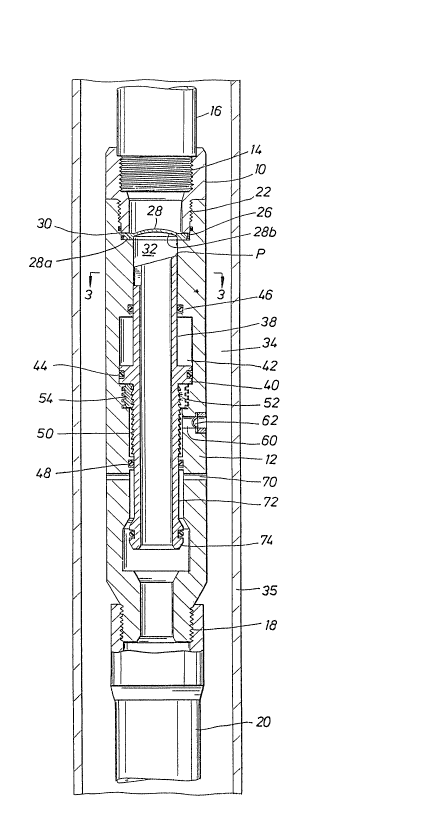
For simplicity, the housing of the disc valve of this
invention is shown in two parts, upper housing section 10
and lower housing section 12. Actually lower housing
section 12 is made up of a number of tubular members
connected together by ~hreaded connections~ Upper housing
section 10 has female threads 14 for connec~ing the housing
to pipe ~string 16. Lower housing section 12 has threads 18
for connecting the housing to pipe string 20 that extends
below the valve.
: Thè two housing sections are connected by threads 22.
These are straight threads so that downwardly facing annular
shoulder 26 on upper housing section 10 will clamp disc 28
between ~it a~nd~upwardly facing shoulder 30 on lower housing
section 12. Outer annular portion 28a of the disc is
~.~J ~ ~
. ' ''~ '' ' ' .
': ' ' , ' . :
5~3~
,,
clamped between the two shoul~ers while central portion 28b
extends across and closes bore 32 of the housing. Outer
annular portion 28a carries seal rin~ 29 to prevent the flow
of fluid around the outside of the disc.
The central portion of the disc is convex in the
direction that the expected differential pressure across the
disc will act. For example, in most cases there will be no
fluid pressure above the disc or only that required for a
water blanket, as in a drill stem test operation resulting
in the pressure of the fluid in annulus 34 between the
housing and casing 35 being higher than the pressure in the
tubing. Therefore, the differential pressure across the
disc is in an upwardly direction.
Tubular mandrel 38 is located below the disc in the
bore of the housing. Piston 40 is attached to the mandrel
and located in cylinder 42 formed by a short section of
increased diameter in lower housing member 12. Piston 40
carries seal ring 44 and cylinder 42 is isolated- from
pressure in the annulus by seal rings 46 and 48. Below
piston 40, downwardly facing buttress type threads 50 on the
mandrel engage upwardly facing buttress threads on split
ring 52. When the mandrel is moved upwardly by fluid acting
on piston 40 the threads will exert a lateral force on split
ring 52 causing it to expand and allow the threads on the
mandrel to ratchet past the split ring as the mandrel moves
upwardly but will prevent downward movement of the mandrel
relative to the split ring. Mating threads 5q on the outer
surface of split ring 52 and the inner surface of the lower
,, :~, . .
:
, ~ :
.
. .
~j59~
-- 5
housing member hold the split ring from moving upwardly with
the mandrel while allowing the ring to expand sufficiently
for the inner threads to ratchet.
The pressure for moving piston 40 and mandrel 38
upwardly to open the valve is supplied to cylinder 42 below
the piston through lateral opening 60 in the sidewall of
lower housing section 12. This passage is closed by rupture
disc 62, which is designed to remain intact when exposed to
the normally expected differential pressure between the
fluid in the annulus and atmospheric pressure in cylinder
42. When it is desired to open -the valve, the pressure in
the annulus is raised at the surface until rupture disc 62
fails. Annulus pressure then acts against the bottom side
of piston 40 and moves the mandrel up and opens the valve.
The mandrel opens the valve by shearing central por-
tion 28b of disc 28 from most of annular portion 28a clamped
between the two housing members. In accordance with this
invention, disc 28 is made of ductile material tha~ can bend
~ ~n~
; ` - without breaking, such as Inconel 600~`
Further, in accor`dance with this invention, to open the
valve, the central ,portion of the disc is sheared from the
~annular portion, but not completely so that the central
portion will remain a~ttached to the annular portion over a
I narrow section that will bend without breaking to allow the
central por~ion to be moved to a position adjacent the side
of the~bore of the housing. To do this the central portion
is sheared from the annular portion progressively from one
; side of the bore to the other until the material connecting
.
:
.. ~. . :. . .
. ~ . .. .
~ 3s3~
the two portions will bend rather than shear under the force
of the mandrel.
To concentrate the shearing stress properly on the disc
to get the progressive shearing of the central portion from
the outer annular portion, the upper end of mandrel 38 lies
in a plane that makes an angle with the longitudinal axis of
the bore so that the initial contact between the end of the
mandrel and the disc occurs between point P on the high side
of the end of the mandrel and all of the orce exerted by
the annular pressure acting on piston 40 will be
concentrated on the disc over a very small area causing it
to fail in shear rapidly. Then as the mandrel moves
upwardly, the point of contact between the disc and the
mandrel will move around the central portion of the disc in
both directions from the point of initial engagement toward
the opposite of the disc. As the disc is sheared from the
outer annular port~on and the two points of contact move
closer to the opposite side from the initial contact, the
disc will tend to begin moving upwardly at some point where
it is easier to relieve the upper force of the mandrel by
bending rather than shearing until the central portion of
the disc will be bent upwar~ly along the inner wall of
housinq section 10, as shown in Figure 2.
At this point, the valve is fully open, no fragments
have been produced to clog up chokes and the like, and the
central portion of the disc has been moved out of the way of
flowing fluids and in a position where it will not interfere
with the passage of instruments and the like. Mandrel 38 is
.-, - - , :
- ` . '~ ~ . .
' :: ` .: . ' ` ` :
5~39;~
-- 7
now held in its upward position, as shown in Figure 2, by
split ring 52 and the upper end of the mandrel will hold
central portion 28 from being moved back toward bore 32 of
the housing by fluid flowing by the disc.
To insure that the central portion of the disc is not
completely severed frorn the outer annular portion, slot 66
is located in the mandrel on the side opposite point P so
that after the central portion of the disc has been sheared
by the mandrel ~o where only the portion between the inner
central portion and the outer annular portion directly above
slot 66 remains, the disc will be forced to bend upwardly
out of the way of the mandrel since there will be nothing to
contact this connecting section and cause it to shear.
In the embodiment shown, tubing string 20 extending
below the valve is connected to annulus 34 through lateral
opening 70 and bore 72 of the housing to keep the pressure
inside pipe string 20 and the annulus equal. Before the
valve has been opened and the mandrel moved to the position
shown in Figure 2, seal 76 carried by lower end 74 of the
mandrel has moved upwardly into engagement with bore 72 to
prevent further communication between the annulus and the
bore of the pipe string~
From the foreqoing it will be seen that this invention
is one well adapted to attain all of the ends and objects
hereinabove set forth, together with other advantages which
are obvious and which are inherent to the apparatus and
structure.
. . .
. .
- : : : :, ., : ,
: ~
Si5~
It will be understood that certain features and
subcombinations are of utility and may be employed without
reference to other features and subcombinations. This is
contemplated by and is within the scope of the claims.
Because many possible embodiments may be made of the
invention without departing from the scope thereof, it is to
be understood that all matter herein set forth or shown in
the accompanying drawings is to be interpreted as
illustrative and not in a limiting sense.
.,
: ~
' ~
,,, ~,,: : ~ ,. . .