Note: Descriptions are shown in the official language in which they were submitted.
~6~
TITLE OF THE INVENTION
POWER-AND-FREE CONVEYOR
BACKGROUND OF THE INVENTION
The present invention relates to a power-and-
free conveyor.
Power-and-free conveyors are already well known
which comprise a power line, a free line coextensive with
the power line thereabove, a multiplicity of pivotally
movable pushers adapted to travel with a drive chain for
the power line, engaging dogs mounted on carrier free
trolleys on the free line, and anticoasting dogs mounted
on the free trolleys and each opposed to the engaging dog.
These conveyors are used for automating flow production.
With the conveyor line system, carriers are switched for
joining or diversion from one line to another article
processing line, or the pushers propelling carriers are
changed over to other pushers. A carrier stopping device
or the like which is separate from the power-and-free
conveyor is conventionally used in such a case for joining
or diverting carriers or for changlng pushers. The system
therefore has the problem of requiring a very high equip-
ment cost and a wide space.
Accordingly, i-t has recently been desired to
provlde a power-and-free conveyor in which pushers can be
~2~
250~8-57
changed over or carriers can be joined together or diverted
without necessitating any special device other than the conveyor.
The conventional conveyor has another problem. Since
the engaging dog and the anticoasting dog are fixed to the free
trolley, the engagement of the pusher with the engaging dog exerts
great impact on the free trolley and consequently to the carrier,
causing trouble to the wor~ on the article in transit, such as a
motor vehicle assembly, and further producing noises.
SUMMARY OF THE INVENTION
The present invention provides a power-and-free conveyor
comprising a power line, a free line coextensive with the power
line, a multiplicity of pivotally movable pushers adapted to
travel with a drive chain provided for the power line, and free
trolleys attached to carriers on the free line, each of the
pushers being generally T-shaped when seen from the direction of
travel of the conveyor and including an attaching member and a
horizontal engaging member provided rearwardly in the direction of
travel of the attaching member, the horizontal engaging member
comprising a center portion having a dog engaging face and
opposite side portions each having an overrunning dog passing
inclined face, said center portion extending toward said free line
further than said side portions, each of the free trolleys having
an engaging dog comprising a pair of opposed vertical engaging
portions, the vertical engaging portions being spaced apart from
each other transversely of the free line at a specified distance
and each having at an end in the direction of travel of the
conveyor a pusher depressing inclined face, each free trolley
-2-
1~66~7 2508~-57
having an anti-co~.sting dog opposed to the engaging dog, the anti-
coasting dog having an outer end extending toward said power line
to a level su:Eficient for the outer end to come into contact with
said center portion of said hori20ntal engaging member outside of
a transfer zone and with the overrunning dog passing inclined face
of either side portion of the horizontal engaging pusher member in
a transfer zone, the horizontal engaging pusher member being
engageable with at least one of the opposed vertical engaging
portions of the engaging dog, whereby interfering engagement
between the pusher and the anti-coasting dog in the transfer zone
is avoided.
With the power-and-free conveyor disclosed herein, one
pusher can be changed over to another, or carriers can be switched
:Erom one line to another for joining or diversion properly without
necessitating any special device, while the conveyor is very
simple in construction and is very low in equipment cost.
Furthermore, the pusher is engageable with the free trolley
engaging dog or the carrier can be stopped without subjecting the
carrier to any impact and without producing noises. The conveyor
therefore assures very quiet efficient flow production, for
example, of motor vehicles~
BRIEF DESCRIPTION OF THE DRAWINGS
Figure 1 is a fragmentary left side elevation on an
enlarged scale showing a power-and-free conveyor;
Figure 2 is a view in section taken along the line II-II
in Figure l;
-3
~26~0~7
25088-57
Figure 3 is an enlarged perspective v:iew showing a
pusher;
Figure 4 is an enlarged view in section taken along the
line IV-IV in Figure 2;
-3a-
~;60~L'7
Fig. 5 is a fragmentary left side elevation on
an enlarged scale showing the conveyor with a carrier at
rest;
Fig. 6 is an enlarged fragmentary bottom view
in section taken along the line VI-VI in Fig. 5;
Fig. 7 is a fragmentary plan view schematically
showing a power line switch portion of the conveyor;
Fig. 8 is a left side elevation of Fig. 7;
Fig. 9 is an enlaryed view in section taken along
the line IX-IX in Fig. 7; and
Fig. 10 is an enlarged fragmentary side elevation
of the conveyor showing a pusher as it is being overrun
by a carrier.
DESCRIPTION OF THE PREFERRED EMBODIMENT
The terms "front," "rear," "right" and "left"
as herein used are based on Fig. 1. "Front" refers to the
left side of Fig. 1, "rear" to the right side thereof,
"right" to the back side of the plane of Fig. 1, and "left"
to the front side of the same.
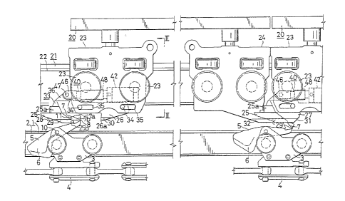
With reference to Figs. 1 to 3, a power-and-free
conveyor, which is of the type to be installed under the
floor, comprises a power line 1 composed of a pair of
opposed power rails 2, a free line 21 composed of a pair
of opposed free rails 22 and coextensive with the power
line 1 thereabove, a multiplicity of pivotally movable
--4--
~26G()~
pushers 5 adapted to travel with a drive chain 4 for the
power line l, and a pair of front and rear free trolleys
23, 24 attached to each carrier 20 on the free line 21.
The front free trolley 23 comprises a main body 23A and a
S slider 33 provided inside the main body 23A and slidable
forward or rearward. The slider 33 is providedon each of its
right and left sides with a pair of outwardly projecting
slide pins 34, 34 inserted in slots 35, 35 extending
longitudinally of the trolley and formed in the opposed
side walls of the main body 23A(. Accordingly, the slider
33 is slidable forward or rearward over a distance
corresponding to the amount of movement of the pins 34, 34
in the slots 35, 35. The slider 33 has at its front end
a downwardly projecting engaging dog 25 and at its rear end
an anticoasting dog 26 opposed to the engaging dog 25.
The slider 33 is connected to the main body 23A
by a shock absorber 40.
Each pusher 5 comprises an attaching member 6
pivo-ted by a pin lO to a power trolley 3 and an engaging
member 7 provided horizontally at the forward end of the
attaching member 6, the pusher 5 being generally T-shaped
when seen from front. The engaging member 7 includes a
center portion 7a having an increased thickness and a dog
engaging face 8 at its rear end, and opposite side portions
7b, 7c having a reduced thickness and an overrunning dog
~2660~L7
passing inclined face 9 which extends fowardly upward from
the rear edge of each side portion.
Each engaging dog 25 comprises a horizontal
connecting portion 25a integral with the front end of the
slider 33 and vertical engaging portions 25b, 25c extending
from -the opposite ends of the portion 25a, the engaging
dog 25 resembling a gate when seen from front. Each of the
vertical engaging portions 25b, 25c has at its front end
a pusher depressing inclined face 28 extending obliquely
forwardly upward.
The vertical engaging portions 25b, 25c of the
engaging dog 25 are formed each at its outer end with an
inclined face 29 for depressing the pusher 5 from one side.
Each of the side portions 7b, 7c of the horizontal engaging
member 7 of the pusher 5 has at its outer end a side
collision preventing inclined face 11 which is adapted to
come into contact with the inclined face 29. These faces
29 and 11 are inclined at an angle of about 30 to about
45 degrees.
The anticoasting dog 26 opposed to and spaced
at a distance from the engaging dog 25 on the slider 33
has its outer end 26a held at a level for this end 26a to
come into contact with the overrunning dog passing inclined
faces 9, 9 of the side portions 7b, 7c of the engaging
pusher member 7. The dog 26 has on each side of its outer
o~
end an inclined face 30 for depressing the pusher 5 side-
ways.
As seen in Fig. 4, the shock absorber 40 comprises
a cylinder 42 pivoted -to the free trolley main body 23A
by a pair of opposite pins 41, 41, a piston 43 slidably
housed in the cylinder 42 and having an orifice 44 extend-
ing through the piston longitudinally of the cylinder for
passing air or like fluid, and a piston rod 45. The piston
rod 45 has one end fixed to the piston 43 within the
cylinder 42 and the other end attached to a connector 46.
Outside the cylinder 42, the connector 46 is attached by
a pin 47 to an upward projection 36 at the front end of
the slider 33. A bellows-shaped tubular protective cover
48 is provided between and interconnects the connector 46
and the front wall of the cylinder 42. The portion of the
piston rod 45 projecting forward from -the cylinder 42 is
covered with the protective cover 48.
An accumulating cam 27 is attached to the rear
free trolley 24 of the carrier 20. The accumulating cam
27 is in the form of a bar, has at its rear end an inclined
face 31 for depressing the pusher 5 when the pusher
approaches from behind and is formed on each side of its
lower end with an inclined face 32 for depressing the pusher 5
sideways.
When the pusher 5, travelling with the drive
--7--
60~'7
chain 4, comes into engagement with the engaging dog 25
on the front trolley 23 of the carrier 20, the piston rod
45 of the shock absorber 40 is advanced forward to move
the piston 43 forward wi-thin the cylinder 42 at the same
time, causing air or like fluid in the space on the front
side of the piston 43 within the cylinder 42 to flow through
the orifice 44 into the space on the rear side of the
piston, whereby the impact due to the engagement of the
pusher 5 with the engaging dog 25 is mitigated.
While the carrier 20 is in travel in usual state,
the horizontal engaging member 7 of the pusher 5 is in
engagement with the opposed vertical engaging portions 25b,
25c of the engaging dog 25 as shown in Fig. 2.
When the carrier 20 is to be stopped at a desired
location on the conveyor line, a carrier stopping device 50
is used as shown in Figs. 5 and 6. The device 50 comprises
a disengaging member 51 generally T-shaped when seen from
below and disposed at one side of the conveyor line
horizontally movably. The member 51 includes a central
disengaging portion 52 and stoppers 54, 54 at opposite sides
of its front end. The disengaging portion 52 has at its
rear end an inclined face 53 for depressing the hori~ontal
engaging member 7 of the pusher 5 to release the pusher 5
from the engaging dog 25 on -the front trolley 23. The
stoppers 54, 54 are adapted -to come in-to contact with the
front ends of the engaging portions 25b, 25c of the
engaging dog 25.
The stopper-equipped disengaging member 51 of
the carrier stopping device 50 is usually disposed at one
side of the conveyor line in a standby position at a
distance therefrom.
When a desired carrier 20 is -to be stopped, the
disengaging member 51 is hori~ontally shifted from the
standby position -to above the conveyor line. When the
front free trolley 23 of the carrier 20 approaches as
propelled by a pusher 5, the inclined face 53 of the
central disengaging portion 52 depresses the pusher 5 out
of engagement with the engaging dog 25. While the pusher
continues to advance as held depressed by the lower surface
of the disengaging portion 52, the front ends of the opposed
vertical engaging portions 25b, 25c of the engaging dog 25
come into contact with and are stopped by the stoppers 54,
54, whereby the slider 33 integral with the engaging dog
25 is retracted. The slider 33 retracts the piston rod
45 of the shock absorber 40 and also the piston 43 within
the cylinder 42 thereof, causing air or like fluid in the
space behind the piston 43 to flow through the orifice 44
into the space on the front side of the piston. This
mitigates the impact due to the contact of the engaging
portions 25b, 25c with the stoppers 54, 54, permitting
_g_
~6~7
the front free trolley 23 and the carrier 20 to stop
slowly. With the carrier 20 thus brought to a halt, the
piston 43 of the shock absorber 40 wi-thin the cylinder 42
is positioned at the rear end thereof, ready for the
subsequent travel of the carrier 20.
When a carrier 20 is to join the preceding carrier
20 at rest, theinclined face 31 at the rear end of barlike
accumulating cam 27 on the rear free trolley 24 of the
preceding carrier 20 at rest depresses the center portion
of the pusher 5 propelling the front free trolley 23 of the
following carrier 20, bringing the pusher 5 out of engage-
ment with the engaging dog 25 of the front free trolley
23. Subsequently, the front end of the dog 25 comes into
contact with the rear end of the rear free trolley 24 of
the preceding carrier 20 a-t rest, whereby the engaging dog
25 and the slider 33 integral therewith are slowly retracted
to permit the following carrier 20 to stop slowly under
the action of its shock absorber 40. After -the following
carrier 20 has been thus stopped, the piston 43 within the
cylinder 42 of the shock absorber 40 is positioned at the
rear end thereof and is ready for -the subsequen-t travel of
the carrier 20.
Figs. 7 to 10 show a specific arrangement wherein
a carrier 20 on one free line 21 is forwarded by pushers
5A, 5B on two different power lines lA, lB.
--10--
~.26~7
The power-and-free conveyor of the type installed
under the floor and shown in Figs. 7 to 9 comprises
first and second power lines lA, lB arranged partly in
parallel, a free line 21 partly coextensive with the two
power lines lA, lB thereabove, many pivotally movable
pushers SA, 5B and adapted to travel with drive chains 4 of
the power lines lA, lB, respectively, and an engaging dog 25
mounted on the free front trolley 23 of each carrier 20 on
the free line 21 and engageable with the pushers 5A, 5s.
Each of the first and second power lines lA, ls
is composed of a pair of opposed steel channel members
serving as power rails 2A or 2B. The free line 21 comprises
a pair of opposed free rails 22 each in the form of a steel
channel member. At a section P where the first and second
power lines lA, lB extend in parallel, the power lines lA,
lB are arranged at opposite sides of the free line 21.
The operation of the conveyor will be described
next.
Before the carrier 20 on the free line 21 reaches
the power line parallel section P, the opposite side
portions 7b, 7c of the horizontal engaging member 7 of a
pusher 5A on the first power line lA are in engagement with
the opposed vertical engaging portions 25b, 25c of the
engaging dog 25 on the carrier 20 as seen in Fig. 2 to
propell the carrier 20. When the carrier 20 approaches
~66(~17
the parallel section P, -the left side portion 7b of the
engaging member 7 of the pusher 5A comes into engagement
with the right vertical engaging portion 25c of the engaging
dog 25 as shown in Fig. 9 since -the first power line lA is
shifted wi-th respect to the free line 21. Pushers 5B on
the second power line lB are free to travel until they
reach the section P.
Beyond the section P, the first power line lA
extends away from the free line 21, so that the pusher 5A
is disengaged from the right engaging portion 25c of the
engaging dog 25 to leave the carrier 20. In the parallel
section P, an advancing pusher 5B on the second power line
lB comes into engagement with the left engaging portion 25b
of the engaging dog 25 on the carrier 20, which is there-
after propelled by the pusher 5B on the second power line
lB. Beyond the section P, the second power line lB extends
immediately below the free line 21, so tha-t the opposite
side portions 7b, 7c of the engaging member 7 of the pusher
5B are brought into engagement with the opposed vertical
engaging portions 25b, 25c of the dog 25 as shown in Fig. 2.
The firs-t power line lA and the second power line
lB may be the same or different in the speed of travel of
the pushers 5A and 5B. The carrier 20 can be forwarded
irrespective of the speed difference between the pushers
5A and 5B.
-12-
~X6~0~L7
More specifically sta-ted, no problem of course
arises when the pushers SA, 5B on the first and second
- power lines lA, lB are driven at equal speeds.
When the pusher 5A on the first power line lA
is slower than the pusher 5B on the second power line lB,
the carrier 20 as brought to the parallel section P by
-the slower pusher 5A can be subsequently forwarded by the
faster pusher 5B without any problem.
Finally, suppose the pusher 5A on the first power
line lA is faster than the pusher 5B on the second power
line lB. When the carrier 20 is brought into the section
P as propelled by the faster pusher 5A, with the slow
pusher 5B already positioned in the section P, the upper
end of the slow pusher 5B is depressed by the inclined
face 28 at the front end of the engaging dog 25 on the
carrier 20,and the lower end 26a of the anticoasting dog
26 further comes into contact with -the overrunning dog
passing inclined surface 9 of the horizontal engaging
member 7 of the pusher 5B to depress the pusher 5B as
seen in Fig. 10. Consequently, the carrier 20 overruns
the pusher 5B. At a location beyond the section P, the
faster pusher 5A on the first power line lA leaves the
carrier 20, so that the slow pusher 5B on the second power
line lB thereafter overtakes the carrier 20 to further
propel the carrier 20. Thus, no problem arises.
~60~L7
Since the slider 33 having the engaging dog 25
and the an-ticoasting dog 26 is connected by the shock
absorber 40 to the main body 23A of the front free trolley
23 of each carrier 20, the pusher 5 is engageable with the
engaging dog 25 with diminished impact without produ_ing
noises by the action of the shock absorber 40.
It is noted that the engaging dog 25, the anti-
coasting dog 26 and the accumulating cam 27 on the carrier
20 have on their opposite sides pusher depressing inclined
faces 29, 30 and 32, respectively, and that each end of
the horizontal engaging member 7 of the pusher 5B has the
side collision preventing inclined face 11. Accordingly,
when the carrier 20 propelled by a pusher 5A on the first
power line lA and a pusher 5s on the second power line lB
enter the parallel section P a-t the same time, the pusher
depressing inclined face comes into contact with the
collision preventing inclined face 11 of the pusher 5B to
depress the pusher 5B. Consequently, no side collision
occurs.
With the power-and-free conveyor of the present
invention, carriers 20 can be switched from one line to
another for joining or diversion in the same manner as
in the above embodiment although not shown.
The shock absorber 40 is not limited to the-illus-
tra-ted structure but may comprise a coiled spring or the like.
-14-
6601~7
Although the present invention has been described
above as embodled as a power-and-free conveyor of the type
to be installed under the floor, the invention is similarly
applicable to overhead power-and-free conveyors by modifying
the arrangement of components and inverting -the relation of
the pusher 5 to the opposed members involving gravity.
Although the illustrated carrier 20 has a pair of
front and rear free trolleys 23, 24, two intermediate free
trolleys may be connected between these trolleys, with an
article support member supported by the intermediate
trolleys, when elongated articles are to be transported.