Note: Descriptions are shown in the official language in which they were submitted.
~Z~6~
The present Inventlon relates to camplng stoves and In
partlcuiar to flame-free, catalytlc stoves.
The conventlonal camping stove of the type deslgned to
flt In a backpack or the llke conslsts of a burner unlt adapted
to screw or clamp onto a can contalnlng ~ supply of fuel such as
propane or butane. Whlle such stoves meet the prime obJectlves
of belng llght-welght and hence easlly portable, they suffer from
the serlous drawback of relylng on an open flame to produce heat.
The flame poses a flre hazard particularly when used In a dry
locatlon. In addltlon, the flame Is subJect to belng extln-
gulshed, or the heat therefrom to belng dlspersed durlng wlndy or
raln condltlons. A further problem wlth such stoves Is that they
permlt only a llmlted degree of throttllng and hence, must burn
at substantlally the same rate In all condltlons.
In vlew of the above, the presen~ Inventlon provldes an
Improved camplng stove whlch Is less sensltlve to weather condl-
tlons than conventlonal, flame type stoves.
The present Inventlon also provldes such a stove whlch
may more readlly be throttled as requlred to Increase or decrease
the rate of combustlon.
The present Inventlon agaln provldes a camplng stove
whlch Is more fuel efflclent than conventlonal stoves and whlch
ylelds less obJectlonable emlsslons than conventlonal stoves.
Accordlng to the ~resent Inventlon therefore there Is
provlded a catalytlc stove comprlslng a fuel/alr mlxlng chamber
for generatlng a fuel/alr mlxture and havln~ an Inlet and an oUt-
let; a dlffuser surroundlng the chamber outlet; a plate overlylng
` the dlffuser, sald plate havlng an Inner face, an exlt face
opposed to and spaced away ~rom sald Inner face and a grld of
openlngs Interconnectlng sald ~aces for passlng the fuel~alr mlx-
ture from the mlxlng chamber; preheatlng means for preheatlng
,'~ ' .
",
.,
' ~
~6;~
sal d Plate; said Inner face belng dlrected toward sald chamber;
and sald exlt face dlrected away from sald chamber, sald plate
; belng provlded wlth a catalytlc coatlng only on sald exlt face
and extendln~ mlnutely Into the openlngs as compared to the over-
all length of the grld For generatlng flameless heat by catalytlc
combustlon of the fuel/air mlxture substantlally at sald exlt
face only wlthout dlrectly heatlng the Inner face due to the
thlckness of the plate. Sultably sald preheatlng means comprlses
a flame holder dlsposed about sald chamber outlet and posltloned
wlthln sald dlffuser. Deslrably sald dlffuser comprlses a trun-
cated, Inverted cone and sald flame holder comprlses a truncated
perforated cone.
In one embodIment of the present Inventlon the stove
~urther comprlses fuel/alr Ignlter means In sald chamber allgned
wlth sald flame holder for causlng Inltlal combustlon of the
fuel/alr mlxture exltlng sald flame holder for preheatlng sald
catalytlc coatlng on sald plate, thereafter combustlon occurrlng
only at sald plate by the catalyst.
In a further embodlment of the present Inventlon the
dlFfuser further comprlses a pan support extendlng about sald
plate grld, sald support Includlng support surfaces extendlng
outwardly beyond the exlt face of sald plate.
Thus, In accordance wlth the present Inventlon the camp
stove comprlses an elongated fuel-alr mlxlng chamber In the form
of an elongated tube. A fuel tank coupllng Is provlded at the
Inlet of the chamber. A dlffuser Is provlded surroundlng the
outlet of the chamber. A plate provlded wlth a grld overlles the
outlet end of the dlffuser. The Plate Is monollthlc metalllc or
ceramlc member wlth between 200 and 400 openlngs per Inch
thereln, the openlngs belng on the order of ,06H x .06~ and .044"
x .044", respectlvely. The plate has an exlt face wlth a cat-
alytlc coatlng thereon extendlng mlnutely Into the Interstlces ofthe grld. The catalytlc coatlng Is formed from the group con-
. ~_ z _
., i
, ..,~
~2~6~
slstlng of platlnum, palladlum, rhodlum and Irldlum.
The present Inventlon wlll be further Illustrated byway of the accompanylng drawlngs, In whlch:-
Flg. 1 Is a slmpll~led slde elevatlonal sectlonal vlewof a catalytlc s~ove In accordance wlth the present Inventlon;
~5
- 2a -
~ ,,
', . ~ !
~LZ66;~
¦ Fig. 2 is a sectional view taken along reference line
2-2 of Fig. 1 in the direction indicated by the arrows;
Fig. 3 is a simplified enlarged side elevational view
j of the stove plate; and,
!l
I Fig. 4 is a fragmentary enlarged schematic plan view of
the plate grid.
¦ Detailed Descri~tion of the Preferred Embodlment:
,1
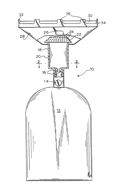
Reference is now made to the drawings and to Fig. l in
particular wherein a stove 10 in accordance with the present
lnvention is depicted. The stove is designed to be used
with a conventionaL fuel can or tank 12 containing liquid
butane or propane. To this end, the top of tank 12 contains
a coupling for connection to a mating coupling provided at
the bottom of the stove. A valve 14 is provided at the
inlet to the stove for regulating the flow of fuel from the
tank into the stove.
The stove includes a mixing chamber in the form of an
elongated tube 18.
An orifice 16 is provided at the inlet to the mixing
tube 18 which comprises the main body of stove 10. The
orifice is fixed and serves to regulate the flow of fuel
from tank 12 when valve 14 is open. The orifice
~ ~ produces
6~ a high velocity jet of fuel ~ ~into tube 18. Ambient
air which enters the tube 18 through an inlet opening 20 is
,, sucked into the tube where i~ is mixed with the gas to form
, -3
- ~,
Il
,1
1266~1X
a combust~ble mixture. The relative sizes of the orifice
and tube determine the resulting ratio of air to fuel
I passiLtg through~the stove.
~¦ At the top end of tube 18 a flame holder 22 in the form
of a perforated truncated cone is provided. The flame
holder 22 serves as a cap for the tube so that the
~¦ perforations 24 extending through the cap provide the only
exit for the fuel/air mixture passing through the tube. As
, shown, the perforations 24 are distributed substantially
uniformly over the flame holder surface.
An ignition port 28 extends through the flame holder
22. A spark igniter, utilizing, for example, a flint or
piezoelectric element may be provided in the ignition port
in the manner common in conventional gas stoves.
A diffuser 28 comprising an inverted, truncated cone
, extends upwardly from the side of tube 18 adjacent to its
¦ upper end. As shown, the ignition port 28 passes through
the diffuser. The bottom of diffuser 28 is sealed to the
outer surface of tube 18 so that the diffuser 28 acts as a
funnel direating the gas/air mixture upwardly and outwardly.
A plate 30 is provided extending across the open top end of
the diffuser 28. A gas1cet 32 seals the edge of plate 30 to
a rim 32 which, in turn, is sealed to or formed integral
with the top edge of the diffuser. Rim 34 is provided with
spaced projections 36 that extend beyond the top face of
plate 30. These projections serve as a support for pots or
pans to be heated on the stove. The plate 30 is shown in
: I
jl ~4~
. .
i'
" '
~2~6~
~ome detail in Figs. 3 and 4. As shown, the plate is a
generally pancake-shaped member which may be formed of a
ceramic or metal. The plate is formed as a monolith with a
relatively large number of small openings extending
therethrough. The number of openings should be on the order
of 200-400 per square inch.
An lmportant aspect of the present invention resides in
~he fact that a catalytic surface is applied as a coating to
the outer (i.e. exit) face of plate 30 extending into the
interstices of the grid to a depth of approximately 1 or 2
.~, mm. This depth bei~such as to complete combustion of the
~/C/~ fuel/air mixture in the presence of the catalyst. The
6~q catalyst is applied only as a surface coating to plate 30.
The catalyst may be platinum, palladium, or other rare metal
such as rhodium or iridium.
In operation, the valve is first opened to permit fuel
to flow from the tank through the orifice into the mixing
tube.
As the gas passes through the tube it entrains air
~/6/ 1 thereby creating a flamable mixture. The spark igniter is
~ ~ then activated or a flame is passed through the ignition
6fl6/~ 1~ port to ignite the gastair mixture at the top of the flame
~,( ; ,j holder. After several seconds the catalyst is heated and
the flame is extinguished by turning off the gas flow. The
iI valve is then reopened to re-establish gas flow and after a
,~ few seconds the~top portion of the plate 30 glows from the
catalytic combustion that is taking place. Food may then be
i cooked or water boiled by placing a pan on the pot/pan
supports 36. Heating takes place by means of radiant
heating an by convection of the heated gases passing
lZ66;~1~
adjacent to the cooking utensil. Since the present stove
operates without a flame, it is less sensitive to wind than
are conventional flame stoves. In addition, the catalytic
stove throttles better than conventional stoves since there
is no need to support a flame.
~¦ Thus, in accordance with the above, the aforementioned
objectives are effectively attained.
. .
. ~ .
: , ,
.
: l :
1 :
'
'
!
i
....