Note: Descriptions are shown in the official language in which they were submitted.
~26~890
CROSS REFERENCE TO RELATED APPLICATIONS
The present invention relates to the inventions
described in the following applications all of which are
assigned to the assignment of the present invention.
Brolin Application Serial No. 527,220 filed on
January 13, 1987 entitled Induction Heating Pressure
Welding.
Brolin Application Serial No. 540,007 filed on June
18, 1987 entitled Induction Heating With Adjustable
Linear Bus Bar.
Brolin et al Application Serial No. 539,997 filed
on June 18, 1987 entitled Inert Atmosphere Control For
Induction Heating Pressure Welding System.
Brolin et al Application Serial No. 540,006 filed
15 June 18, 1987 entitled Dual Induction Heat Pressure
Welding Control Circuit.
BACKGROUND OF THE INVENTION
Field of the Invention
The present invention relates to welding and
more specifically relates to welding metal members
together by induction heating weldable surfaces of each
member to upsetting or welding temperature and
immediately thereafter forcing the surfaces together
with sufficient force to upset the weldable surfaces and
weld them together.
SUMMARY OF THE INVENTION
According to an aspect of the invention, an
apparatus for induction heating and pressure welding
weldable surfaces of two members together comprises:
a frame;
a hydraulic cylinder secured to said frame and
having a piston rod adapted to support a first member
and being movable between a surface heating position and
a surface upsetting position;
clamping means secured to said frame and adapted to
securely clamp second member in fixed position with a
r~
`~
.
lZ66890
weldable surface disposed in alignment with the weldable
surface of said first member;
hood means for directing a laminar flow of
substantially inert gas past said weldable surfaces for
purging air from said surfaces;
means defining an induction heating coil movable
between a first position disposed between and spaced a
short distance from said surfaces for heating said
surfaces to an upsetting temperature, and a second
position out of alignment with said weldable surfaces
for allowing said hydraulic cylinder to immediately
thereafter force said first member against said second
member with sufficient force to upset said heated
surfaces and weld said two surfaces together,
means for directing a high frequency current
through said coil when in said first position to heat
said surfaces to an upsetting temperature;
said clamping means including a bodily adjustable
sub-frame movably supported by said frame, a first
V-block gripper head rigid with said sub-frame, a second
V-block gripper head carried by said sub-frame and
movable relative to said first V-block gripper head for
clamping said second member therebetween, and adjustment
means for moving said sub-frame between a position
wherein said weldable surfaces of said first and second
members are out of alignment with each other to a
position wherein said surfaces are in weldable alignment
with each other;
said sub-frame abutting a portion of said frame
having T-slots therein, a plurality of hydraulic
cylinders secured to said sub-frame, a piston rod in
each cylinder, a T-bar operatively connected to each
piston rod and slidably received in said T-slots,
when said sub-frame is in locked position, each
piston rod being retracted to rigidly connect said
sub-frame to said frame,
'' ~
' ~ '
.
,
126~8go
2a
when said sub-frame is to be adjusted each piston
rod being moved to permit sliding movement of said
T-bars in said slides.
According to a further aspect of the invention, an
apparatus for induction heating and pressure welding
weldable surfaces of two members together comprises:
a frame,
a hydraulic cylinder secured to said frame and
having a piston rod adapted to support a first member
and being movable between a surface heating position and
a surface upsetting position;
clamping means secured to said frame and adapted to
securely clamp second member in fixed position with a
weldable surface disposed in alignment with the weldable5 surface of said first member;
hood means for directing a laminar flow of
substantially inert gas past said weldable surfaces for
purging air from said surfaces;
means defining an induction heating coil movable
between a first position disposed between and spaced a
short distance from said surfaces for heating said
surfaces to an upsetting temperature, and a second
position out of alignment with said weldable surfaces
for allowing said hydraulic cylinder to immediately
thereafter force said first member against said second
member with sufficient force to upset said heated
surfaces and weld said two surfaces together,
means for directing a high frequency current
through said coil when in said first position to heat0 said surfaces to an upsetting temperature;
said hood means including open cell foam rubber
pads therein for allowing said induction heating coil to
be moved into said hood between said weldable surfaces
and out of said hood and for maintaining a substantially
inert atmosphere around said weldable surfaces which is
at a higher pressure than the pressure externally of
i266890
2b
said hood and progressively decreases in pressure from
one end to the other end of said hood.
According to a further aspect of the invention, an
apparatus for induction heating pressure welding two
weldable surfaces of two members together, comprises:
means defining at least one induction coil;
pressure applying means for moving at least one of
the members along a pressure applying path;
means for supporting the two members with said
weldable surfaces spaced from each other;
means for providing a laminar flow of a
substantially inert gas around said weldable surfaces;
means for establishing relative movement between
said members and said induction coil for first
positioning the coil in close proximity between said
weldable surfaces and for thereafter spacing said coil
from the pressure applying path of movement of said
weldable surfaces;
means for directing a high frequency current
through said coil when positioned between said weldable
surfaces to heat said surfaces to an upsetting
temperature;
means for forcing said weldable surfaces together
with sufficient force to upset said heated surfaces for
welding said surfaces together when said coil is spaced
from said surfaces;
said coil means having opposed heating surfaces
disposed between weldable surfaces of different areas,
and means for positioning one of said heating surfaces
of said coil means closer to the weldable surface having
the larger area with the other heating surface being
spaced a lesser distance from the smaller weldable
surface for controlling the temperature rise in each
weldable surface for substantially simultaneously
raising both weldable surfaces to the upsetting
temperature.
~'
1266890
2c
According to another aspect of the invention, a
method of induction heating pressure welding weldable
surfaces of two members together using at least one
induction coil and pressure applying means for moving at
least one of the members along a pressure applying path
comprises the steps of:
supporting the two members with said weldable
surfaces spaced from each other;
providing a laminar flow of a substantially inert
gas around said weldable surfaces;
establishing relative movement between said
members and said induction coil for first positioning
the coil in close proximity between said weldable
surfaces and for thereafter spacing said coil from said
pressure applying path of movement of said weldable
surfaces;
directing a high frequency current through said
coil when between said weldable surfaces to heat said
surfaces to an upsetting temperature;
forcing said weldable surfaces together with
sufficient force to upset said heated surfaces for
welding said surfaces together when said coil is spaced
from said surfaces; and
wherein the weldable surfaces are of different
areas, and wherein the coil has opposed heating
surfaces disposed between the weldable surfaces of
different areas; and including the step of positioning
one of said opposed heating surfaces of said coil closer
to the weldable surface having a larger area than the
surface having a smaller area for controlling the
temperature rise in each weldable surface for
substantially simultaneously raising both weldable
surfaces to the upsetting temperature.
According to another aspect of the invention, an
induction heating pressure welding apparatus, a rotary
bus bar joint comprises:
~A
1;~66890
2d
a two piece conductive bus bar including a tongue
operatively connected to a source of high frequency
current;
first insulator means for electrically insulating
one piece of said bus bar from the other piece;
a two piece conductive arm mounted on said two
piece bus bar for arcuate movement about an axis with
said arm pieces being electrically connected to
associated bus bar pieces;
second insulator means for electrically insulating
one piece of said arm from the other piece;
an induction coil conforming to the shape of the
weldable surfaces to be welded together and having two
ends;
means electrically connecting one end of said coil
to one piece of said arm and electrically connecting the
other end of said coil to said other piece of said arm;
third insulating means for electrically insulating the
ends of said coil and said electrical connecting means
from each other;
means for pivoting said arm and said coil about
said axis; and
means for cooling said bus bar, said tongue, said
arm, said coil and said connecting means.
According to another aspect of the invention, an
induction heating pressure welding apparatus, a rotary
bus bar joint comprises;
a two piece electrically conductive bus bar
operatively connected to a source of high frequency0 current;
a two piece electrically conductive tongue
projecting from one end of said bus bar and having first
holes therein defining a pivot axis;
first electrical insulating means disposed between5 said two pieces of said bus bar and said tongue for
lZ66890
2e
providing two separate circuits, said electrical
insulating means in said tongue lying in a predetermined
plane;
a two piece electrically conductive arm having
second pivot holes in one end portion and each arm
having a separate mounting block on the other end
portion;
tubular connecting means of non-conductive material
inserted through said first and second holes for
pivotally connecting said two piece arm in electrical
conductive engagement with said two piece tongue;
second electrical insulating means disposed in a
plane normal to the plane of said first insulating means
for electrically separating said two pieces of said arm
from each other for providing two separate electrical
circuits;
a tubular electrically conductive induction coil
shaped to conform to the shape of the weldable surfaces
of two members to be welded together and having spaced0 end portions;
a first electrically conductive connecting means
connecting one end portion of said coil to one of said
blocks;
a second electrically conductive connecting means
connecting the other end portion of said coil to the
other block;
a mounting blade of non-conductive material
connected to said two piece arm;
means operatively connected to said arm for moving
said two piece arm and coil in an arcuate path around
said pivot axis; and
means for cooling said bus bar, said tongue, said
arms, said conducting means and said coil.
BRIEF DESCRIPTION OF THE DRAWINGS
Figure 1 is an exploded perspective of major
components of the induction welding apparatus of the
1266~90
2f
present invention, certain parts being broken away and
other parts being shown in section.
Figure lA is a central vertical section of two
members welded together with an inflatable air plug in
one member.
Figure 2 is a front elevation of the induction
welding apparatus, certain parts being cut away.
Figure 3 is a top plan of the induction welding
apparatus, certain parts being cut away.
Figure 4 is a left end view of the apparatus of
Figure 1 with certain parts being cut away.
Figure 5 is an exploded perspective of a rotary bus
bar joint and two induction coils with certain parts
being cut away to illustrate portions of the water
cooling passages within the rotary joint
Figure 6 is a diagram in perspective illustrating
the route and direction of flow of cooling liquid
through the left half of the bus bar, the bus bar joint
and the left induction coil.
Figure 7 is an operational view in side elevation
illustrating the induction coils in solid lines in a
member heating position within an inert atmosphere hood,
and in an inoperative position in phantom lines.
Figure 8 is an operational view in frontal
elevation illustrating the induction coils in member
l266aso
--3--
heating position, the inert atmospheric hood being shown
in phantom lines.
Figure 9 is an operational view illustrating
the two members welded together with the inert atmospheric
hood moved to the left with the piston rod of a hydraulic
cylinder.
Figure 10 is a perspective in central section
illustrating a pair of induction heating coils adapted to
independently heat different size members to an upsetting
temperature and having laminations to aid the heating
process.
Figure 11 is a perspective similar to Figure 10
but illustrating laminated induction coils for heating
cylindrical members to upsetting temperature.
Figure 12 is a perspective similar to Figure 10
but illustrating laminated induction coils for heating
square or rectangular members to a bonding temperature.
DESCRIPTION OF THE PREFERRED EMBODIMENT
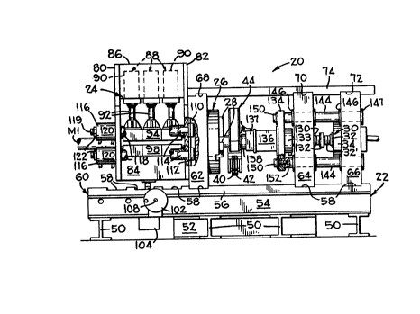
The induction welding apparatus 20 (Figs. 1-4)
of the present invention comprises a heavy frame 22 which
supports an adjustable clamping mechanism 24 capable of
rigidly supporting a first workpiece or member Ml,
illustrated as a tube, which may vary in size between
about 2 1/2 inches to at least 6 inches in diameter. The
member Ml is accurately centered on a fixed longitudinal
axis A with a conventional chuck 26 having movable jaws 28
that are simultaneously adjusted by a screw mechanism and
wrench (not shown). The frame 22 also supports a
bydraulic cylinder 30 having its longitudinal axis
concentric with axis A. The cylinder includes a piston
rod 32 and a threaded extension 32' which extends out of
the left hand end (Fig. 2) of a cylinder case 34 and is
operatively connected to an adapter having a cavity 35
(Figs. 8 and 9) to snugly receive one end of a second
member M2 which is to be induction welded to the first
. '
.
i266890
~4 -
member Ml. The second member M2 is illustrated as a short
tube in all Figures except Figure lA which illustrates a
male lug M2' that is induction welded to the first member
Ml; and a female lug M2~, shown in phantom lines,
connected to the male lug M2' by pin 36. Figure lA
illustrates one use of the induction welding apparatus
which is to weld long (20-40 foot) tubular members to
male and female lugs for quickly, accurately and reliably
manufacturing lattice booms for use on cranes or the
like. An expandable plug 37 is inserted in the member Ml
and is expanded into sealing engagement in the member by
compressed air from valve and conduit 37' to prevent air
in the tube Ml from flowing around the weldable surfaces
Sl,S2 (Fig. 8) during the heating and welding operation.
The frame 22 also indirectly supports a rotary
bus bar joint 38 (Figs. l, 5 and 7) which includes two
induction coils 40,42 which are moved between the ends of
members Ml,M2 (Fig. 8) when the weldable end surfaces Sl
and S2 of the two members are to be heated to an upsetting
temperature and are thereafter immediately rotated away
from the members Ml,M2 as shown in Figure 9 to allow the
cylinder 30 to force the member M2 into engagement with
the member Ml. The heating and upsetting operations take
place within an inert atmosphere hood 44 which is
connected to the piston rod 32 of the cylinder 30 as best
shown in Figure 2. A pair of heat stations containing
transformers 46,48 (Figs. 3 and 4) are also mounted on the
frame 22 for horizontal adjustment. The transformer 46
provides current to the induction heating coils 40, while
the transformer 48 provides current to the coil 42.
More particularly, the frame 22 includes a
plurality of heavy transversely extending I-beams 50 and a
short longitudinally extending I-beam 52 (Figs. l and 4)
that are supported on a concrete floor, which beams
support a pair of longitudinally extending I-beams 54. A
i266890
--5--
horizontal floor plate 56 is provided with a plurality of
transverse grooves 58 therein. The I-beams and plate 56
are bolted together to define a rigid base 60.
As best shown in Figure 2, three thick
transverse walls 62,64 and 66 are fitted into associated
ones of the grooves 58; and also are fitted into grooves
68,70 and 72, respectively, formed in a short cover plate
74. The floor plate 56 and cover plate 74 are connected
to the walls 62,64 and 66 by a plurality of capscrews (not
shown). It will be noted that the wall 62 has a hole 76
(Fig. 1) therein for receiving member Ml and may be
secured to any of the four grooves 58 on the left portion
of the floor plate 56 if the member Ml is excessively long
and requires that the clamping mechanism 24 be moved to
the left. If the mechanism 24 is ~oved to the left, a
longer top plate is provided and is appropriately grooved
for connection to the walls by capscrews.
The clamping mechanism 24 (Figs. 1-4) includes
a pair of spaced walls 80,82 rigidly secured to a sturdy
base 84 and a top wall 86 to which a plurality of
hydraulic clamping cylinders 88 are secured. The
cylinders 8B each include a cylinder case 90 (Figs. 1 and
4) and a piston rod 92. An upper V-block gripper head 94
is secured to each piston rod 92 and has two gripper jaws
96 disposed at 90 to each other which cooperate with a
pair of lower gripper jaws 96 which are also disposed at
90 to each other and are secured to a lower V-block
gripper head 98 that is rigidly secured to the base 84.
It is important that the jaws 94,96 be quite long (about
10 inches) as illustrated and be angled at 90 to each
other to preserve the ovality of the member Ml, if the
member is a tube as illustrated, and also to firmly clamp
the member Ml from movement when subjected to an upsetting
force which may be as high as about 236,000 pounds,
depending upon the size of the members Ml,M2 being welded
2 ~ 90
--6--
together. The clamping mechanism 24 and the strength of
the apparatus 20 is capable of upsetting metal having a
weldable surface area of up to about 30 square inches.
The illustrated clamping mechanism is capable of handling
5 members Ml Up to 6 inches in diameter.
The clamping mechanism 24 (Figs. 1-4) is
adapted to be moved horizontally, as previously mentioned,
by mounting the wall 62 in different ones of the grooves
58 and providing a cover plate 74 of appropriate length.
The entire clamping mechanism 24 is also vertically
adjustable by means of a conventional right angle screw
jack 100 which is manually operated by a handwheel 102.
The jack is mounted on a sub-frame 104 (Fig. 4) having
supporting bars 106 engaging flanges of the I-beams 54.
Longitudinal movement of the clamping mechanism 24 to
different position along the floor plate 56 is allowed
after first removing the hand wheel 102 and its shaft 108.
In order to accommodate vertical movement of
the clamping mechanism 24 and yet maintain the mechanism
firmly against the wall 62 during the upsetting operation,
the wall 62 is provided with a pair of T-slots 110 (Fig.
2) which slidably receive T-bars 112 therein. Each T-bar
112 is connected to one end of a piston rod extension 114
of a hollow center hydraulic cylinder 116. Each piston
rod extension 114 extends through a tube 118 which abuts
the end walls 80,82. Each extension 114 is coupled to an
associated piston rod 119 ~Fig. 1) which extends through
cylinder case 120 with a nut 122 on its protruding end.
When it is desired to adjust the clamping mechanism 24
vertically, hydraulic pressure is supplied to the left end
of each hydraulic cylinder case 120 thus moving the piston
rods 119 and extensions 114 to the right out of clamping
engagement with the wall 62. When it is desired to firmly
clamp the mechamism 24 to the wall 62 hydraulic pressure
is applied to the right side of each cylinder 120 thus
~Z66890
--7--
overcoming the substantial upsetting force applied against
the member Ml during the upsetting operation. Yertical
keyway guides (not shown) may be formed in adjacent
surfaces of the walls 62,82 to receive a key for
accurately guiding the clamping mechanism when moved
vertically.
The hydraulic cylinder 30 (Figs. 1-3) has its
cylinder case 34 mounted in a bore in the wall 66. A
partially threaded extension 32' of the piston rod 32
extends through a hole in the wall 64 which is countersunk
to receive a stop ring 130 that acts as an abutment to be
engaged by a calibrated adjustable stop 132 which limits
the stroke of the piston rod extension 32' when moving in
the upsetting direction which is to the left in Figures
1-3. The ring 130 has two functions; the first function
is to prevent accidental crushing of the fingers of an
operator when the calibrated ring 132 is moved into
engagement with the ring 130, and the second function is
to permit easy replacement of the ring 130 when the ring
is crushed by repeated impacts with the calibrated ring
132. The calibrated ring 132 is threaded on the piston rod
and has calibration marks thereon which permit the
upsetting stroke to be easily and accurately adjusted in
one thousands of an inch increments.
The left end (Fig. 2) of the piston rod
extension is rigidly secured to a transducer 133 which is
secured to a tool fixture platen 134 which has a spacer
box 136 bolted thereto. An inert atmosphere hood
supporting block 137 and an adapter 138 are releasably
connected to the space box 136. The adapter 138 is
provided with the previously mentioned member supporting
cavity 35 (Figs. 8 and 9) The cavity 35 is machined to
conform to the external shape of the member M2 which is to
be welded to the member Ml as previously described. The
adapter 138 is releasably connected to the member M2 by a
~266890
--8--
set screw 140 as best shown in Figure 8 and may be removed
and replaced by other adapters if a different workpiece,
such as members M2' or M2- (Fig. lA) are to be welded to
the member Ml.
The tool fixture platen 136 (Figs. 1-3) is
rigidly secured to four tie rods 144 each of which extends
through bushings 146 fitted in the bores in the walls 64
and 66. Each tie rod 144 has a dust cap 147 closing the
bores in the wall 66, and has a reduced diameter
shouldered portion on the other end which snugly fits
within a bore in the tool platen 134. AS best shown in
Figure 2, cap screws 150 are secured in threaded bores 152
in the tie rods 144 thereby rigidly connecting the fixture
platen 134 to the tie rods 144.
As previously described, the pressure applying
stroke of the piston rod extension 32' may be stopped by
abutment between the ring 130 (Fig. 2) and the calibrated
ring 132.
When welding a large plurality of identical
members together, such as member Ml and M2 (Figs. 8 and 9)
the calibrated ring 132 may be screwed away from the ring
130 so that the rings do not contact during the pressure
upsetting operation. The required compressive force can
be determined and set in a control circuit (not shown)
connected to the transducer 133 for providing the desired
upsetting force on the ends of the members Ml and M2
without further operator assistance or the need of a
physical stroke limiting stop. Thus, the force transducer
133 is relied upon to provide the proper welding pressure
to assure that the heated ends of the members Ml and M2
- are reliably welded together.
Although not illustrated, it will be understood
that the cylinder 30 is connected to a source of hydraulic
fluid through conventional fast acting valving and a
plurality of conventional hydraulic accumulator tanks
1266890
which compress a gas above the hydraulic fluid for
assuring rapid actuation of the ram in the upsetting
direction.
As diagrammatically shown in Figures 1-3 and 7-9,
an inert atmosphere control hood 44 is removably
mounted on the hood supporting block 137. A
substantially inert gas such as argon, helium, nitrogen
or a mixture of about 95~ argon and 5~ hydrogen is
directed past the weldable surfaces S1, S2 of the
members Ml and M2 during the induction heating operation
and the pressure upsetting or welding operation which
occurs rapidly within a matter of seconds. The inert
gas removes oxygen from the surfaces to be welded
thereby preventing poor welds due to oxidation and
resulting scaling of the material from the surfaces
being welded together. The specific details and the
manner of operation of the inert atmosphere control hood
44 are disclosed in Brolin et al Application Serial No.
539,997 filed on June 19, 1987. It will also be
understood that the apparatus 20 is ideally suited for
welding in an oxygen free atmosphere such as in outer
space since the welding process is clean and spatter
free.
The two transformers 46,48 (Figs. 3 and 4), the
rotary bus bar joint 38, and the induction coils 40,42
are adjustably supported on the frame 22 by
conventional lathe type way 162. The way 162 includes a
carriage 164 (Fig. 4) rigidly secured to the frame 22
and to a slide 165 upon which the transformers 46,48 and
bus bars 166,166' (Figs. 5 and 7) of the rotary bus bar
joint 38 are rigidly supported. The way 162 also
includes a feed handwheel 170 (Fig. 3) and a screw
mechanism (not shown) which enables the operator to move
the transformers 46,48 and induction coils 40,42
longitudinally of the induction welding apparatus 20 to
precisely center the induction
~F~
i~66890
-10-
coils 40,42 between the weldable surfaces Sl,S2 of the
members Ml,M2 to be welded together. The transformers
46,48 are capable of operating at 9,600 cycles per second
but are preferably operated at about 6,000 cycles per
second when welding steel tubes together that are between
about 204 inches in diameter. It will be understood that
different materials may require different frequencies.
The rotary bus bar joint 38 is best illustrated
in Figures 5 and 7 with the flow of coolant through the
bus bar joint being illustrated in Figure 6. Since the
right half of the bus bar joint is a mirror image of the
left half, the left half will be described in detail while
the right half will be identified by the same numerals
followed by a prime (').
The bus bar joint 38 includes a left bus bar
166 which includes a pair of copper mounting blocks
182,184 that are rigidly secured to blocks 185,186 of bus
bars 187,188 of the transformer that are separated by
insulation 190. The right bus bar 166' is, of course,
similarly connected to the right transformer 48.
The left bus bar 166 includes a pair of copper
plates 192,194 brazed to the associated mounted blocks
182,184, respectively. The copper plates and blocks
182,184 are separated by an insulation strip 196 all of
which have a 90 bend therein. The insulation strip 196
projects between the copper blocks 182,184 which ar-e
secured in clamping engagement with the insulation strip
196 by insulated capscrews (not shown) connected to the
insulated wall 186 attached to the transformer 46. ThUs,
the two copper plates 192 and 194 define two spaced
electrical conduits capable of carrying a very high
current.
Two rectangular copper tubes 202,204 are brazed
to the outer surfaces of the plate 192 and to the block
182 which have water passages therein for directing
cooling fluid, preferably water, therethrough. Similar
tubes (not shown) but similar to tubes 197',198' on the
right bus bar 166' are brazed to the outer surface of
plate 194 and to the block 184 which has water passages
therein for cooling the plate 194.
~26689~
-11-
The other ends of the copper plates 192,194 and
copper tubes are brazed to associated copper blocks
212,214 which are connected to copper blocks 216,218 by
brass capscrews (not shown). The copper blocks 216,218
are brazed to copper tongues 222,224 all of which are
separated by an insulation strip 225. The blocks and
tongues form extensions of the plates 192,194 and are
subject to frictional wear and preferably have their outer
surfaces silver plated to reduce friction and to improve
conductivity.
The copper blocks 182,184,212,214,216,218; and
the four copper tubes 202,204 (and the equivalents of
right tubes 197',198') have fluid flow passages therein as
best illustrated diagrammatically in the cooling conduit
system 226 of Figure 6. Inlet water enters the cooling
conduit system through conduit 228, flows through passage
230 in the block 182, through the copper tubes 202,204
into blocks 212 and 216 and then combine in a passageway
232 in blocks 216 and 212. A transverse passage 234 in
blocks 212,214 then causes the fluid to flow from block
212, through a passage in the insulation strip 196 and
through passages in the block 214,218, and the outer tubes
197,198 connected to the copper plate 194 for return to
the block 184 and discharged through a conduit 236. The
cooling water dissipates the heat formed in the bus bar
166 to a temperature that is low enough to prevent burns
if touched by the operator.
In order to transmit electrical current and
cooling water to the induction coil 40, and to change the
input and output current paths leading to the coil 40 from
separated vertical paths to separated horizontal paths, a
rotatable arm 240 is formed from two copper sections 242
and 244.
The arm section 242 is non-linear in order to
rotatably sandwich the tongue 222,224 between arm sections
~266a90
-12-
242 and 244. The arm section 242 includes a rectangular
copper cooling tube 246 with the arm section and tube
brazed to each other and to a lower copper block 248
having water passages 250,252 (Figs. 5 and 6) therein with
the passages 252 communicating with an inlet water hose
254.
The arm section 244 is a linear section which
includes a copper coolant tube 256 and an upper copper
block 258 having coolant passages 260,262 communicating
with opposite ends of the tube 256. The arm section 244
copper tube 256 and the upper block 258 are brazed
together. A vertical electrical insulation strip 266 is
disposed between the outer ends of the arm sections
242,244 and a horizontal insulation strip 268 is
disposed between the lower block 248 and upper block 258
to electrically insulate the two arm sections and blocks
from each other. The surfaces of the arm sections 242,244
which rotatably contact the surfaces of the tongues
222,224 are preferably silver plated to minimize
frictional wear and to increase and improve conductivity.
In order to rotatably connect the left arm 240
to the tongues 222,224; and to connect the equivalent
right arm 240' to the tongues 222' and 224'; an induction
coil mounting blade 269 and pivot shaft 270 are rigidly
connected together and are constructed from a non-metallic
material. one side of the shaft 270 rotatably extends
through a flanged and threaded tubular bushing 271. The
bushing has an adjustment nut 272 screwed thereon which
bears against the resilient O-ring 273 of non-conductive
material which may be compressed a sufficient amount to
establish good electrical contact between the tongues
222,224 and the associated arm sections 242,244. The ends
of the pivot shaft 270 extends through holes 274,274' in
lever arms 276,276' and are rigidly connected thereto by
set screws 278,278'. The lever arms 276,276' are securely
i266890
-13
connected to the rotatable arms 240,240' and to the coil
mounting blade 269, by non-conductive bolts 278 which
extend through the holes in the lever arms 276,276',
through the holes in the lower blocks 248,24~' and upper
blocks 258,258', and through holes in the coil mounting
blade 269.
The left coil 40 is formed from copper tubing
which is shaped to conform to the shape and size of the
weldable surface Sl (Fig. 8) to be heated to an upsetting
temperature. One end of the coil is brazed to an upper
tube 282 which has its other end welded to an upper
mounting block 284 having a flow passage 286 therein that
communicates with the passage 262 in the upper block 258
when the block 258 and 284 are bolted together.
Similarly, a lower copper tube 288 is brazed to the other
end of the coil 40 and to a lower copper block 290 which
is bolted to the lower copper block 248. The coolant flow
passage 250 in block 248 communicates with a flow passage
292 in block 290. Thus, coolant flows from inlet hose 254
through conduits in the direction indicated in Figure 6.
More particularly, the coolant flows from hose 254,
through lower conduit 252, through copper tube 246 into
passage 250 in lower block 248, through a passage 2~2 in
block 290, through the lower copper tube 288, through the
coil 40, through the upper tube 282, through the passage
286 in the upper block 284 and into passage 262 in the
upper block 258 which then flows through copper tube 256
and passage 260 in the upper block 258 and is discharged
through a hose 293.
It will be noted that the ends of the coils
40,42; upper tubing 282 and lower copper tubing 288 upper
block 284 and lower block 248 are electrically insulated
from each other by an insulation strip 294. These
components are also insulated from each other by one or
more vertical insulation strips 296. In order to firmly
1266890
14
support the coils 40,42, angle bars 298,298' are welded
to the lever arms 276,276' and project below the
induction coils. A non-metallic insulation plate 299 is
bolted to the bars 298,298' and provide support for the
lower surfaces of the copper tubes 288,288' that are
connected to the coils 40,42.
A fast acting air cylinder 300 (Figs. 4, 5 and 7)
has a piston rod 302 pivotally connected to a rod 304
secured to the lever arms 276,276'; and has its case end
pivotally connected to a bracket 308 (Fig. 4) that is
secured to the previously described longitudinally
movable slide 165 that permits coils 40,42 to be moved
to different positions longitudinally of the induction
welding apparatus 20.
Figure 10 illustrates members Mla and M2a having
weldable surfaces Sla and S2a of different
cross-sectional areas. In order to simultaneously raise
both surfaces Sla and S2a to their upsetting
temperatures, a large coil 40a is disposed adjacent the
large surface Sla while a smaller coil 42a is disposed
adjacent the surface S2a. In order to more effectively
concentrate the induced heat into the surfaces Sla and
S2a, both coils 40a and 42a have U-shaped laminations
310,312 formed thereon, which laminations 310,312 are
preferably constructed of silicon iron of about 0.007
inches thick and control very high magnetic fields. A
non-metallic insulating disc 314 is disposed between the
two coils 40a,42a.
A pair of sensors, preferably optical temperature
sensors 316,318 such as infrared pyrometers, are
provided to detect the temperature of the surfaces Sla
and S2a. The amount of current directed to the coils
40a,42a or the length of time the current is applied, or
both, may be varied so that both surfaces Sla, and S2a
are raised to the upsetting temperature at the same
time. Brolin et al Canadian application S.N. 540,006
~26689~1
filed June 18, 19~7 discloses and claims the preferred
circuitry for controlling the heat applied to the
surface Sla and S2a along with the controlling of many
other functions of the apparatus.
Figure 11 discloses a pair of induction coils 40b
and 42b adapted to heat the end surfaces Slb and S2b of
solid cylindrical members Mlb and M2b to upsetting
temperatures. The end surfaces of the members are
drilled to provide short holes 318,320 therein which
receive some of the upset material during the pressure
applying upsetting operation.
Figure 12 discloses a pair of substantially square
induction coils 40c and 42c adapted to heat the end
surfaces Slc and S2c of square or rectangular members
Mlc and M2c to upsetting temperature.
In operation of the induction welding apparatus 20
(Figs. 1-4) of the present invention, the operator first
determines the type of members Ml and M2 to be induction
heated and pressure welded together. If the members are
of relatively small diameter tubular construction such
as 2 1/2 inch outside diameter tubes having wall
thicknesses of about 0.2 inch, are of the same material
and having weldable surfaces Sl,S2 of the same size,
the operator may select a single coil such as coil 40
along with certain cooling passages to simultaneously
heat both surfaces Sl and S2 of the members Ml and M2 to
be welded together.
Assume, however, that the operator selects the two
coils 40,42 (Figs. 1-4 and 5) to weld members Ml,M2
together. The operator then sets up the machine by
first mounting the two coils to the blocks 248,258 and
248',258' as shown in Figure 5. The operator then
positions member M2 in the cavity 35 (Fig. 8) of the
adapter 138 with the piston rod 32 of the ram 30 fully
retracted. The operator then operates the handwheel 170
(Fig. 3) to adjust the two _ _
~'
1 2 6 ~ 8
-16-
transformers 46,48 and the coils 40,42 longitudinally of
the apparatus 20 to an induction heating position wherein
a small air gap is disposed between the weldable surface
S2 of the member M2 and the adjacent face of the coil 42.
The operator then places the member Ml in the chuck 26 and
in the clamping mechanism 24 and clamps the member Ml
between the jaws 28 of the chuck manually; and thereafter
hydraulically closes jaws 96 by actuating the hydraulic
clamping cylinders 88 with the weldable surface Sl of
member Ml being spaced from the adjacent surface of the
coil 40 by a small air gap when the coils 40,42 are in
their heating position illustrated in Figure 8. With the
member Ml clamped in the clamping mechanism 24, the
operator determines if the longitudinal axis of the member
Ml coincides with the longitudinal axis of the member M2.
If the axes of the members do not coincide, the operator
actuates cylinders 116 to move the piston rods 119 and
their extensions 114 to the right (Figs. 1 and 2) and then
operates the handwheel 102 to raise or lower the member Ml
until it is properly aligned in welding position with the
member M2. The operator then actuates a conventional
valve to cause cylinders 116 to move the piston rods and
rod extensions 114 to the left (Figs. 1 and 2) thereby
firmly clamping the clamped mechanism 24 against the wall
62 and the member Ml between the jaws 94,98.
If the member Ml is tubular and the end
portions of the tube adjacent the surface Sl is not sealed
by another means, an expandable plug 37 (Fig. lA) is
expanded by air pressure from air conduit and valve 37' to
prevent air from flowing around the weldable surfaces
Sl,S2 during the induction heating and pressure upsetting
operations.
After the members Ml and M2 have been mounted
as above described, the inert atmosphere hood 44 (Figs.
35 1-3 and 7-9) is mounted on the hood supporting block 137
126~890
17
in the induction heating position as shown in phantom
lines in Figure 8 and in the upsetting positian as shown
in Figure 9. The hood 44 and its manner of operation is
fully disclosed and claimed in Brolin et al Application
Serial No. 539,997, filed on June 18, 1987.
sriefly, the hood ~4 is manually mounted about and
sealed to the outer surfaces of the members Ml and M2
and includes an upper portion removably connected to a
lower portion so that both portions may be removed from
the members when welded together. When in operative
position a substantially inert gas such as argon,
helium, nitrogen or a 95% mixture of argon and hydrogen
are directed past the weldable surfaces Sl,S2 in a
laminar flow which purges air from the surfaces Sl,S2
and discharges it through diffusers or pads, which are
preferably formed of vinyl or urethane foam, in the
- lower end of the hood. The foam pads are split to
permit the coils 40,42 to move into and out of the hood.
After the induction heating pressure welding
apparatus 20 has been set up as above described, the
operator actuates control circuits which are disclosed
and described in the Brolin et al Application Serial No.
540,006 filed on June 18, 1987 to place the machine in
operation.
With the inert gas flowing past the surfaces Sl and
S2, and with the two coils raised to operative position
shown in Figure 8, an oxygen detector senses the gas in
the hood 44 and energizes the induction coils when the
detector detects an insufficient amount of oxygen in the
hood to adversely affect the weld. The control circuit
maintains the induction coils energized until
temperature sensing means in the control circuit
indicate that the weldable surfaces Sl,S2 have been
raised to the upsetting temperature at which time the
circuit first
~'
~26~;890
18
actuates the air cylinder 300 to move the induction
coils 40,42 from between the members Ml,M2 and then
actuates the hydraulic cylinder 30 thereby forcing
member M2 against member Ml with sufficient force to
upset the heated material adjacent the weldable surfaces
Sl, S2 as shown in Figure g thus completing the weld.
The induction heating and pressure welding steps require
about five seconds. During this time the coolant,
preferably water, is directed through the bus bar and
induction coil assembly as shown in Figures 5 and 6 to
cool the assembly. It will be understood that the
copper tubing 246,256 and 246',256' (Fig. 5) cool the
surfaces of the rotary joint.
After the weld has been completed the set screw 140
(Fig. 8) is released from member M2, the cylinder 30
retracts the box 136 and block 137 (~ig. 9) away from
member M2, is retracted to the Figure 8 position, the
gas supply to the hood 44 is turned off and the hood is
separated and removed from the apparatus 20. The welded
members Ml,M2 are then unclamped from the chuck 26 and
the clamping mechanism 24 and are removed from the
apparatus 20 thus completing one cycle of operation.
Other cycles of operation on the same type members may
take place without again setting up the machine except
for positioning the members Ml and M2 in welding
position and clamping the member Ml in the heating
position. Also, hood 44 is remounted around the
members Ml and M2 and secured to the hood supporting
member 137.
If tubular members Mla and M2a (Fig. 10) having
different weldable surface areas are to be welded
together, the induction coils 40a,42a are substituted
for the coils 40,42 and the operation is repeated.
If metals of different types, for example, steel to
cast iron or brass to copper are to be welded together,
laminated induction coils of the same size or different
sizes similar to the coils 40a and 42a may be
~'
~266890
-19-
used and be simultaneously raised to the required
upsetting temperatures.
Similarly, the Figure 11 induction heads 40b
and 42b may be substituted for the heads 40 and 42 when
solid metal rods 41b and 42b are to be welded together.
Likewise, induction coils of different shapes and sizes
such as the induction coils 40c and 42c (Fig. 12) may be
used to weld members of different sizes, shapes, and
metals together following substantially the same steps as
described above in regard to welding members Nl and M2
together.
From the foregoing description it is apparent
that the induction heating and pressure welding apparatus
of the present invention is capable of welding metals of
different sizes and shapes and of different types together
while in a substantially inert atmosphere by separately
heating the weldable surfaces of two members by
independently controlled induction coils. Immediately
thereafter, the two members are pressed together with
sufficient force to upset the weldable surfaces thus
welding the two members together. The apparatus is
capable of being manually operated, but is preferably
operated in a semi-automatic manner to provide
consistently good welds when making a plurality of
identical welded parts.
Although the best mode contemplated for
carrying out the present invention has been herein shown
and described, it will be apparent that modification and
variation may be made without departing from what is
regarded to be the subject matter of the invention.
AJM:lu