Note: Descriptions are shown in the official language in which they were submitted.
-1 -
OPTICAL FIBER CQUPLER
Background of the Invention
The present invention re;Lates generally to fiber optic
couplers, and more specifically to single mode to
multimode fiber optic directional couplers.
Fiber opti~ directional couplers are used in
communication networks, optical signal processing, and
sensor systems. For example, fiber optic local area
networks ~LANs) utilize fiber optic couplers to couple
light bet~een a fiber bus and plural work stations, each
of which comprises an optical transmitter and receiver~
Most prior art directional couplers are "reciprocal"
devices, that is, they inherently couple the same fraction
of optical power regardless of whether the coupling is
from a first fiber to a second fiber or from the second
fiber to the first fiber. Non-reciprocal coupling
devices, on the other hand, couple significantly different
fractions of optical power between fibers. Such non-
reciprocal coupling devices are more advantageous than
reciprocal coupling devices for many applications, such as
local area networks. For example, in a local area
network, it is desirable to couple only a small fraction
of the data signal optical power from the bus to each
station, so as to permit the bus to accommodate a large
number of stations. On the other hand, it is desirable
that substantially all of the data signal optical power
generated at each station be coupled to the data bus.
Since reciprocal couplers couple ~he same amount of
optical po~er in both directions (i.e., bus to station or
~tation to bus), the use of such reciprocal couplers in
local area networks severely limits the maximum number of
stations. Similar problems exist in other fiber optic
applications, such as multiplexed sensor networks.
The iEoregoing problems have been addressed in the
prior art by utilizing a nonreciprocal, single mode to
multimode iEiber optic directional coupler. The multimode
~.~ li7013
fiber serves as a da~a bus, while the single mode fiber
serves as a network branch, e.g. for a work station.
Optical data generated at the work station is transmitted
through the single mode fiber for coupling to the
multim~de fiber bus. The prior art couplers are typically
formed by removing a portion of the cladding from the side
of a single mode fiber and a multimode fiber, and then
juxtaposing the portions of the fibers where the cladding
has been removed, so that the fibers are in side by side
relationship. However, to ensure effective coupling
- between the single mode and multimode fiber, the coupled
modes must be phase matched so that ~hey have
approximately the same phase velocity. Since the modes of
a multimode fiber have phase velocities spread over a
1~ substantial range, only a limited number of higher order
modes within the multimode fiber are utilized. The
resulting mode distribution in the multimode fiber is,
therefore, not uniform, and is likely to be influenced by
microbends or other fiber perturbations. Accordingly, the
coupling coefficient of such a coupler may be influenced
by the environment.
Summary of the Invention
The present invention comprises a directional coupler
having first and second optical fibers. The preferred
embodiment of the invention also includes a third optical
fiber. Preferably, the first optical fiber is a single
mode optical fiber. The second optical fiber is a
multimode optical fiber having plural mode groups. In the
embodiment disclosed, the second fiber serves as an
optical bus, while the first and third ~ibers provide
input and outp~t branches for coupling light to and from
the second fiber. Advantageously, the coupler of the
present invention does not require any phase matching of
the modes in the fibers.
Coupling between the fibers is accomplished by means
of a reflector, disposed in the core of the multimode
~ 2G7~3
optical fib2r. The reflect:or is sized and oriented such
that only a small fraction of the light propagating in the
multimode fiber is incident thereon. In the preferred
embodiment, the reflector is disposed at the center of the
fiber core. The light incident on the reflector is
reflected towards the output branch fiber and coupled
thereto, for example, through a graded index lens.
Because the reflector is sized and oriented to intercept
only a fraction of the light propagating in the multimode
fiber, a large number of couplers can be located on a
single fiber bus without substantially degrading the
throughput of the bus.
Light propagating in the input branch fiber towards
the multimode fiber is fo~used on the reflector, for
example, by means of the graded index lens. The reflector
is oriented to reflect this focused light in a generally
cone-shaped beam directed longitudinally down the axis of
the multimode fiber. The cone-shaped beam diverges such
that substantially all of the modes within the acceptance
cone of the multimode fiber are excited. Preferably, the
light is distributed among the mode groups, such that the
optical power in each mode group is proportional to the
number of modes in the mode group. This is accomplished-
by equalizing the intensity of the cone shaped beam
throughou~ the area defined by the acceptance cone of the
multimode fiber. The intensity may be equalized by
selecting the numerical aperture of the multimode fiber
such that only that portion of the reflected beam which
has relatively uniform intensity, referred to as the
"constant intensity beam portion" is within the acceptance
cone of the fiber~ The size of the constant intensity
beam portion may be increased by sizing the reflector
relative to the beam incident thereon such that only the
portion of the light from the input branch fiber which is
within the peak of the approximately Gaussian-shaped
energy distribution is reflected.
Description of the Drawings
These and other features of the present invention are
best understood through reference to the drawings in
which:
Figure 1 is a schematic drawing illustrating the cross
section of a typical single mode optical fiber;
Figure 2 is a schematic drawing illustrating the cross
section of a typical multi-~ode optical fiber;
Figure 3 is a graph showing the energy distribution
pattern for the first order mode of an optical fiber;
Figure 4 is a graph showing the energy distribution
pattern for the second order mode of an optical fiber;
Figure 5 is a schematic drawing illustrating a light
ray being guided within the core of a step index multi-
1~ mode optical fiber, and further illustrating the maximumtotal reflection complimentary angle, beyond which light
rays will cease to be guided by the optical fiber;
Figure 6 is a schematic drawing illustrating a
meridional ray and a skew ray propagating down the optical
- 20 fiber of Figure 5;
Figure 7 is a perspective view of a preferred
embodiment of the coupler of the present invention;
Figure 8 is a partial cross sectional view of the.
coupler of the present invention, ~aken along the lines
8-8 of Figure 7, showing a small mirror disposed a~ the
center of the multi-mode bus fiber;
Figure 9 is a partial cross sectional vlew of the
coupler of Figure 7, illustrating the function of the
. mirror in optically coupling light from the input branch
fiber to the multi-mode bus fiber;
Figure lO is a drawing of an exem`plary Airy
diffraction pattern, showing the far field intensity
distribution of the light reflected from the mirror; .
Figure ll is a partial cross-sectional view of the
coupler of Figure 7, illustrating the function of the
_ . . . . ... . ..... .. .. . .. .
~ 6~0'~
mirror in coupling light from the multi-mode bus fiber to
the output branch fiber;
Figure 12 is a schematic drawing illustrating use of
the coupler of the present invention in one of plural work
stations in a fiber optic local area network; and
Figure 13 is a schemati.c drawing illustrating the use
of the coupler of the present invention in an exemplary
sensor system.
Detailed DescriPtion of the Preferred Embodiment
12 A basic understandin& of mode theory of optical fibers
is helpful in order to fully appreclate the inventive
concepts underlying the coupler of the present
invention. Accordingly, before discussing the structural
and functional aspects of the present invention, a brief
discussion of mode theory will be presented.
Optical fibers may be broadly classified into two
groups, namely, single mode optical fibers and multimode
optical fibers. As their names imply, single mode fibers .
propagate light in only a single mode, while multimode
fibers propagate light in multiple modes. In generalj a
mode may be defined as an optical path in the fiber
through which light propagates unchanged, except for
phase. Thus, a single mode fiber may be viewed as having'
' a single optical path therethrough, while a multimode
fiber may be viewed as having plural independent optical
paths therethrough.
The number of modes which may be supported by an
optical fiber is dependent upon the geometry of the fiber,
particularly the core radius. A typical single mode fiber
is illustrated in Figure 1, while a typical multimode
fiber is illustrated in Figure 2. The single''mode fiber
12 has an inner core 14, surrounded by an outer cladding
16. Similarly, the multimode fiber 18 includes an -inner
core 20, surrounded by an outer cladding 22. As
3~ illustrated, the single mode core 14 is smaller than the
multimode core 20. In general, the number of modes
1~ 6~ 0~
- supported by the fiber is a function of the core radius,
the refracti~e indices of the core and the cladding, and
the wavelength of the light propagating through the
fiber. Furthermore, the exact profile of the refractive
index across the core influences the number of modes
supported. Typically, single mode fibers have a core
radius on the order of 5 to 10 microns, while multimode
fibers typically have a core radius on the order of 50 to
100 microns.
1~Each fiber mode has a cross-sectional energy
distribution which is unique relative to the other
modes. For example, the energy distribution for the first
order, or fundamental, mode is s'hown in Figur~ 3. The Y
axis in Figure 3 represents optical energy, while the X
axis represents distance from the center of ~he fiber
core. As illustrated, the energy distribution of the
fundamental mode is approximately Gaussian shaped, such
that most of the optical energy is concentrated at the
center of the fiber. The geometry of a single mode fiber
is such that only this first order or fundamental mode
will propagate therein. However, as the core radius
increases, other parameters being constant, the fiber will
begin to support additional modes, e.g. second order,'
third order, fourth order, etc. The energy distribution
for the second order mode is shown in Figure 4. `As
illustrated, the optical energy in the second order mode
is distributed in two lobes, both of which are displaced
from the center of the fiber core. In general, the energy
distribution tends to be displaced further from the center
of the fiber core as the order of the mode (i.e. mode
number) increases. Thus, light in the lower 'order modes
tends to propagate clo~er to the center of the fiber core
than the higher order modes.
Each of the above described modes (e.g., first order,
3S second order, third order, etc.) tends to propagate light
at a different velocity. As is well known, imperfections
o~
and perturbations of the fiber will tend to couple light
between the modes. Such coupling increases with
decreasing difference in phase velocity between the
modes. The propagation velocities of the above described
modes are sufficiently dissimilar that these modes are
substantially uncoupled. Thus, light launched in a
particular mode tends ~o remain in that mode for long
distances (e.g., on the order of kilometers for presently
available fibers).
Those skilled in the art will understand that each of
~he abov~ discussed modes consists of a group of closely
related mod~s. For e~ample, the first order mode may be
subdivided into a group of two modes which comprise
polarization modes. The second order mode may be
subdivided into a group of four modes. It is important to
understand that all of the modes within a particular group
of modes have approximately the same phase velocity, while
each of the mode groups differ in phase velocity with
respect to the other mode groups. In general, the nu~ber
of modes in each mode group increases ~ith ehe orde~ of
the mode (i.e., mode number). Thus, the second order mode
- includes a mode group having more modes than the mode
group of the ~irst order mode, the third order mode`
includes a mode group having more modes than the mode
group of the second order mode, etc. For purposes of
reference hereinafter, the term "mode group" will be used
to refer to a group of modes having approximately the same
phase velocity, while the term "mode" will be used in a
general sense as referring to any mode which propagates in
the fiber.
Because the modes within a mode group have
approximately the same phase velocity, light tends to
readily couple between the modes within a mode group.
This coupling is caused by slight intrinsic imperfections
present in all presently available optical fibers. It is
generally assumed that ~here are enough intrinsic
~ 2 ~ ~ O~
imperfections in presently available optical fibers to
cause an even distribution of power among the modes in a
group after propagating only a relatively short distance
along the fiber. Thus, liight coupled to only a single
mode within a mode group will quickly couple to the other
modes within that group.
The foregoing discussion of fiber modes was presented
primarily in terms of field theory. Those skilled in the
art will recognize that modes and mode groups may be
alternatively described in terms of a different theory,
called "ray theory". Under ray theory, the light
propagating in any mode may be represented by a set of
light rays. Referring to ~igure 5, the first order or
fundamental mode is represented by a ray (not shown) which
is coincident with the longitudinal axis 28 of the
multimode fiber core 20. Each of the higher order modes
is represented by a set of rays, which is inclined at an
angle relative to the longitudinal axis 28 of the fiber
core 20. In general, the higher the mode group number,
the greater the angle between ~he set of rays and~the
longitudinal axis 28 of the core. For example, the ray 30
of Figure 5 represents one of the rays within a high order
mode which, for purposes of discussion, will be assumed to
be a mode within the tenth order mode group of a multi-
2~ mode fiber having 15 mode groups. As illustrated, the ray30 intercepts the longitudinal axis of the fiber 18 at an
angle ~. The sets of rays (not shown) representing mode
Groups 11-l5 would thus be inclined from the longitudinal
axis 28 at angles greater than ~, while the sets of rays
(not shown) representing mode Groups 1-9 would be inclined
from the longitudinal axis 28 at angles less tXan ~.
From Figure 5, it may be seen that the ray 30 is
totally internally reflected each time it reaches the
interface between the core 20 and cladding 22, such that
the ray 3C) is guided down the length of the fiber 18.
Such intermal reflection occurs for all of the modes which
~ 7 ~
are supported by the fiber 18, except the fundamental mode
which requires no reflection to be guided within the fiber
core, since it propagates along the axis 28.
As shown in Figure 6, the ray 30 discussed in
reference to Figure 5 propagates down the fiber 18 in a
plane which passes through the fiber axis 28 and extends
from the core/cladding ineerface on one side of the fiber
to the core/cladding interface on the other side of the
fiber. For purposes of reference hereinafter, such a ray
which passes through the central longitudinal axis of the
core 20 as it propagates down the fiber 18 will be
referred to as a "meridional ray"~ In addition to
meridional rays, each mode group also includes rays, such
as the ray 31 in Figure 6, which will be referred to as
"skew" rays. Skew rays are distinguished from meridional
rays in that they do not pass through the longitudinal
axis of the core during propagation, However, all of the
- modes within a particular mode group, whe~her skew or
meridional, are inclined relative to the central
longitudinal axis of ~he core by substantially the ~ame
~ angle. Thus, since the exemplary rays 30 and 31 are
~ithin the s-ame mode group, both of the rays, 30, 31 will
be inclined relative to the central longitudinal axis at
the angle ~. In general, the number of skew rays
aqsociated with a particular merîdional ray increases as
the angle 5 increases. Thus, there are ordinarily more
skew rays associated with higher order modes than with
lowe~ order modes.
Those skilled in the art will recognize that ~he angle
between a par~icular ray and the central longitudinal axis
28 of the core (e.g., the angle ~ for the ray`30) defines
the propagation velocity of the mode represented by the
ray. Accordingly, since all of the rays which comprise a
particular mode group are inclined by substantially the
same angle relative to the longitudinal axis (e.g. the
angle ~ in Figure 5), all of the modes within that mode
~7V~
0
group will propagate liglht at substantially the same
velocity. Conversely, the modes associated with rays
which are inclined from the longitudinal axis 28 at
substantially different angles will propagate light at
substantially different velocities, and will be in
different mode groups.
As it is well known, iin a step index optical fiber,
the rays are reflected at the core/cladding interface by
virtue of the fact that the cladding of an optical fiber
has a refractive index which is lower than the refracti~e
index of the core. The number of rays that will be guided
by the fiber is a function of the ratio of the refractive
index of the core to the refractive index of the
cladding. Rays inclined from ehe axis 28 at an angle
greater than or equal to ~c (Figure 5), referred to herein
as the "total reflection complementary angle", will not be
reflected, but will instead radiate through the cladding
and out of the fiber. This angle ~c is defined in terms
of the refractive index difference between the core and
2~ the cladding as follows:
. .
~C = cos 1 t n2 ) (1.)
where n1 is ~he refractive index of the core and'n2 is the
refractive index of the cladding. Those skilled in the
art will understand that the angle ~c is ~losely related
to the numerical aperture of the fiber.
In a step index fiber having a core of radius a, the
number of rays (M) which are inclined from the axis (28)
at an ang].e less then ~c (and thus, the number of modes
(M) supported by the fiber) may be calculated as follows:
~i70~
V2
~ 2 (2
where:
~ 2 -~ 2
and:
~5 ko ~~-~ (4
where ~ is the wavelength of the light in a vacuum.
It should be noted that the quantity (M) defines the
to~al number of modes in all of the mode groups.
Having briefly discussed some of the basic principles
of mode theory, the present invention will now be
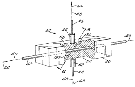
described. As shown in Figures 7 and 8, the coupler 40 of
the present invention comprises a multimode fiber 42
having an inner core 42a and an outer cladding 42b. This
multimode fiber 42 serves as an optical signal "bus" for
the coupler 40. The coupler 40 also includes an input
branch fiber 44, which is preferably a single mode
fiber. The input fiber 44 carries optical signals from a
device, such as a LAN transmitter or a sensor, for
coupling to the fiber bus 42. Additionally, the coupler
may include an output branch fiber 46, which may be either
single mode fiber or multimode mode fiber. However, in
the preferred embodimen~, the output fiber 46 is a single
7 0
-12-
mode fiber. The output fiber 46 carries optical signals
from the fiber bus 42 1:O a device, such as a LAN
receiver. In many sensor systems, however, the output
fiber 46 is not needed.
In the embodiment disclosed, the central longitudinal
axes of the input and output fibers 44, 46 lie along a
common line 48. Additionally, the fibers 44, 46 are
disposed such that the common axis 48 intersects the
central longitudinal axis 49 of the multimode fiber 42 in
direction normal thereto. For stability and rigidity, the
multimode fiber 42 is preferably mounted in support
structure, such as a quartz block 50. As illustrated, the
block 50 has a rectangular cross section. The fiber 42
extends through a central bore in the block 50, which is
disposed along the longitudinal axis of the block 50. The
fiber 42 is bonded wi~hin this bore by means of an
adhesive.
A lens 52, for example, a graded index lens, is
disposed between the output end of the input fiber 44 and
one of the side faces 54 of the block 50. Preferably, the
graded index lens 52 is affixed to the block face 54 and
input fiber 44 by means of an adhesive. Similarly, a
graded index lens 56 is disposed between the input end of
the output fiber 46 and a side face 58 of the block, which
is opposite the side face 54. The lens 56 is similarly
bonded to the block face 58 and fiber 46 by means of an
adhesive.
As shown in Figure 8, a small reflector 60 is disposed
within the core of the multimode optical fiber 42 at the
juncture between the common axis 48 of the fibers 44, 46
and the longitudinal axis 49 of the multimodë fiber 42.
In the preferred embodiment, the reflector 60 is a plane
mirror whlch is shaped as a disk, although it will be
understood that other types of mirror surfaces may be
used. The planar surface of the mirror 60 is disposed at
45 degreesl relative to the central axis of the fiber 42.
7013
The mirror 60 is oriented to receive light propagating
through the multimode fiber 42 in the direction indicated
by the arrow 64 and to reflect such light towards the lens
56 and output fiber 46 for propagation through the output
fiber 46 in the direction indicated by the arrow 66. In
this orientation, the mirror will also be positioned to
receive light propagating through the input fiber 44 in
the direction indicated by the arrow 68, and to reflect
such light for propagation through the multimode fiber 42
in the direction indicated by the arrow 64.
The coupler 40 is a nonreciprocal device, That is,
the fraction of optical power coupled is significantly
differen~ depending upon whether the light is being
coupled ~o the multimode fiber 42 or from the multimode
fiber 42. A relatively high fraction of the light
propagating through the input fiber 44 in the direction 68
will be coupled to the multimode fiber 4~. However, a
relatively low fraction of the light propagating in the
multimode fiber 42 in the direction 64 will be coupled to
the output fiber 46 for propagation in the direction ~6.
The nonreciprocal coupling of the coupler 40 may be more
fully understood through reference to Figures 9 - 11.
Figure 9 is a partial .cross-sectional view which
illustrates optical coupling from the single mode input
2~ fiber 44 to the multimode mode fiber 42. ~ight
propagating through the input fiber 44 in the direction 48
enters the graded index lens 52 as a cone shaped beam 80,
reprçsented by the rays 81. The beam 80 is focused by the
. graded index lens 52 such that the rays 81 converge to a
diameter approximately equal to the diameter of the planar
surface of the mirror 60. Since the surface of the mirror
60 is inclined at an angle of 45 degrees relative to the
central axi.s 49 of the fiber 42, the mirror 60 will
reflect the light beam 80 for propagation down the fiber
42 in the direction 64. The mirror 60 is very small, and
in the preferred embodiment, the mirror is sized to
o~
-14-
intercept only that portion of the optical energy of the
beam 80 which is within the peak of the energy
distribution associated with the single mode fiber 44.
This portion of the optical energy is represented by the
dimension Ep in Figure 3. Because the mirror is small,
the light 80 incident thereon will be reflected as a cone
shaped beam 82, represented by the rays 83. In this
regard, it will be understood that the mirror 60 functions
in a matter analogous to a small aperture (e.g., a
pinhole), such that the reflected light 82 diverges in the
same manner as light passing through a pinhole will
diverge due to diffraction. The Airy diffraction pattern
for the mirror 60 is illustrated schematically in Figure
10 as the pattern 84. For clari~y of illustration, only
the mirror location and the central axis 49 of the fiber
42 are depicted. The arrows radiating from the mirror 60
to the boundaries of the pattern 84 represent the
direction of propagation of various exemplary light rays
within the reflected light beam 82. The length of each
2D arrow represen~s the optical intensity associated with t~e
particular direction of propagation. Thus, the
diffrac~ion pattern 84 indicates the intensity of the
reflected light beam 82 as a function of the direction o
propagation of the light radiating from the mirror
2~ surface. As shown in Figure 10, the intensity of the
reflected light 82 is highest for the light ray which
propagates along the central axi3 49. Those rays which
prop~gate at an angle from the axis 49 decrease in
intensity as the angle increases. As illustrated ! the
reflected light 82 is concentrated principally in an area
defined by a central lobe 86 which extends along the
longitudinal axis 49. In addition9 there are several side
lobes 88 which extend in a generally lateral direction
from the axis 49. The first zero of the diffraction
pattern 84 (i.e. the juncture between the central lobe 86
and the next adjacent side lobe 88) occurs at an angle of
-15-
1.22 ~Id from the longitudinal axis 49. Thus, the central
lobe 84 represents a cone shaped beam of light which
diverges from the fiber axis 49 at an angle of 1.22 ~/d,
where d is the diameter of the mirror 60 and ~ is the
wavelength of the light. The diffraction pattern 84
indicates that this cone shaped beam of light represented
by the central lobe 86 has an intensity which is
relatively constant at locations near the fiber axis 49,
i.e., within an angle r from the axis 49. However, the
1C intensity rapidly drops towards zero as the angle 1.22 ~d
is approached.
Those skilled in the art will recogni2e that only the
portion of the reflected light beam 82 which is within the
"acceptance cone" of the fiber 42 will be guided by the
fiber 42. As is well known, the "acceptance cone" is
defined by the "total reflection complementary angle"
(~c)- Light rays within the acceptance cone ~i.e., those
rays inclined from the central axis 49 by an angle less
than ~c) will be guided by the fiber. Light rays outside
the acceptance cone (i.e., those rays inclined from t~e
central axis 49 by an angle greater than ~c) will no~ be
guided by the fiber. _-
In the present invention, it is preferable that the
reflected light 82 be distributed over all of the mode
groups of the fiber 42. This can readily be accomplished
by insuring that the acceptance cone of the fiber is
smaller than the cone of light represented by the central
lobe 86 of the pattern 84. Stated another way, the total
reflection complementary angle (~c)~ discussed in
reference to Figure 6, should be no greater than the angle
1.22 ~/d, such that the zeros between the lobes 86, 88 are
not subtended by the angle 1.22 ~/d. Thus:
~c ~ 1-22 ~/d
~ 7~
The above relationship may be satisied by properly
selecting the mirror diameter (d), wavelength (~), and
fiber parameters (nl, n2). Note that the angle at which
the first zero occurs varies inversely with the mirror
diameter, and thus, ~ibers having high total reflection
complementary angles ~c) may be accommodated by
decreasing the mirror diameter (d).
Although satisfying the relationship of equation 5
insures tha~ the rei-lected light 82 (Figure 9) will be
introduced into all of the mode groups of the ~iber 42, it
is also preferable to distribute the light among the mode
groups in direct proportion to the number of modes in each
mode group. Since coupling between modes within a mode
group occurs readily over a short distance, such
distribution results in equalizing the intensity among all
of the fiber modes. This distribution of optical power
may be accomplished by insuring that the "total reflection
complementary angle" (~c) is no greater than the angle y,
referred to herein as the "constant intensity cone
angle". As shown in Figure 10, the angle y is that anglé,
measured from the longitudinal axis 49, through which the
intensity of the central lobe 86 is substantially
constant. Stated another way, the angle y is the angle
between the central axis 49 and a point on the central
lobe 86 at which the optical intensity begins to fall
rapidly towards zero. Thus, the angle y subtends a cone
shaped beam of relatively uniform intensity, which is
referred to herein as the "~onstant intensity beam
portion". By insuring that the acceptance cone is no
greater than the constant intensity beam portion, each of
the mode groups will receive li~ht in proportion to the
number of modes in the group so that the modes will be
equalized with respect to intensity. The foregoing may be
expressed mathematically by the following relationship:
~7()1~3
~c ~ r (6)
It should be noted that, if the mirror 60 is located
ae the center of the fiber (i.e. at the axis 49), such as
in the preferred embodiment, only the meridional rays
within each mode group will be excited. However, as
mentioned above, a redistribution of power between the
meridional rays and the skew rays occurs within each mode
group after a short propagation distance through the fiber
42, thereby causing the optical power ~o be equalized
among all modes within a mode group.
t5 It is also possible to improve the power distribu~ion
among modes within a mode group by locating the mirror in
an off-axis position. This cause more skew rays to be
excited, yielding a more even distribution of mode
power.
Although the preerred embodiment utilizes step index
fiber, the present invention may also be implemented
utilizing a graded index fiber. However, in such case, it
is preferable to locate the mirror at the fiber axis,
since of-axis excitation will result in increased
radiation losses, due to the fact that the local "total
reflection complementary angle" (~c) in a graded index
fiber is lower in an off axis position.
~ rom the ioregoing, it will be seen that the coupler
of the present invention is capable of coupling
substantialLy all of the light from the input fiber 44 to
the multimode bus fiber 42. Further, if the mirror size,
wavelength, and fiber para~eters are selected properly,
the coupler 40 distributes the coupled light substantially
evenly over all of the modes of the fiber 42.
Figure 11 is a partial cross-sectional view which
illustrates optical coupling from the multimode fiber 42
~2~7
-1 8
to the output fiber 46~ I.ight propagates through the
multimode fiber 42 in the direction 64 towards the mirror
60. Since the mirror 60 is very small compared to the
core diameter, only a small fraction of the optical power
in the fiber 42 will be incident on the mirror 60. Note
that the light propagating in the direction 64 is incident
on the side of the mirror 60 which is opposite the side
upon which the light beam 80 (Figure 9) is incident.
Thus, in the embodiment disclosed, both sides of the disk
19 shaped mirror have reflective surfaces. The portion of
light propagating in the multimode fiber 42 which is
incident on the mirror 60 i5 reflected therefrom in the
form of a cone-shaped beam 90, represented by the rays
91. The cone-shaped beam 90 propagates in a direction
substantially normal to the fiber axis, and thus, it will
radiate through the cladding without being internally
reflected. After propagating through the cladding, the
beam 90 propagates through the block 50 to the graded
index lens 56. This lens 56 focuses the diverging cone-
shaped beam of light 90 for input to the input end o.f theoutput fiber 46. ..The light 90 then propagates through the
- output fiber-46 in the direction 66.
As previously mentioned, the mirror 60 is extremely.
small, and thus, the fraction of light coupled from the
multimode fiber 42 to the single mode fiber 46 by the
mirror 60 will be small compared to the fraction of light
in the multimode fiber 42 which is not coupled (i.e., the
fraction wh:ich is not incident on the mirror). In optical
systems having a number (n) of the couplers 40 at spaced
intervals along the multimode fiber bus 42 (such as LANs
and sensor networks), the size of the mirror 60 may be
optimized for maximum throughput of the optical power
coupled to the fiber bus 42. As discussed in more detail
hereinafter, the optimized mirror diameter (d) for the
preferred embodiment may be expressed as:
~L~6~YO~;~
_1 9
d s 2a _
~ n-1
As shown in Figure 12, the coupler 40 of the present
invention may be adapted for use in a fiber optic local
area network to provide optic:al communication between the
LAN bus and transmitter/receiver stations located along
the bus. An exemplary LAN station 98 'comprising a
receiver 100 and transmitter 102 is illustrated in Figure
12. The multimode fiber 42 of the coupler 40 serves as
the data bus for the local area network. The fiber bus 42
is coupled to the optical data receiver 100 through the
output fiber 46 of the coupler 40~ while the optical data
transmitter 102 is coupled to the fiber bus 42 through the
input fiber 44 of the coupler 40. The coupler 40 thus
optically couples signals propagating on the bus 42 to the
receiver 100. Similarly, the coupler 40 couples si~nals
generated by the transmitter 102 to the data bus 42. The
fraction of light coupled from the transmitter 102 tP the
bus 42 is large compared to the fraction of light roupled
from the bus 42 to the receiver 100, and thus, the coupler
40 functions as a non-reciprocal coupling device. Because'
only a very low fraction of optical power is coupled to
the receiver 100, a large number of LAN stations 98 may'be
arranged in optical communication along the fiber bus 42.
Another preferred use for the coupler 40 of the
present invention is to multiplex the signals of a sensor
system onto a common return bus. Figure 13 illustrates a
ladder-type sensor system in which the coupler 40 may be
used to particular advantage. This type sensor system is
described in an article by A.R. Nelson and D.H. McMahon
entitled "Passive Multiplexing Techniques for Fiber Optic
Sensor Systems", International Fiber Optical
Communications Journal; Vol. 2, p. 27-30 (March, 1981).
-20-
As illustrated in Figure 13, this sensor system
includes a single mode fiber optic input bus 110, for
receiving an input optical signal. The multimode optical
fiber 42 of the present invention serves as an output
bus. A series of sensors 112(1) to 112(n-1) are optically
connected to receive light irom the input fiber bus 110
through a series of single mode, input branch fibers
113(1) to 113(n-l), respectively. These branch fibers
113(1) to 113(n-l) are coupled to the input bus 110 by
resp~ctive fiber optic directional couplers 114(1) ~o
114(n-1). A sensor 112(n) is optically connected to
receive light directly from the end of the input fiber bus
110.
The sensors 112(1) to 112(n-1) are optically connected
to output light therefrom to respective branch fibers
44(1) to 44(n-1), respectively. These branch fibers 44(1)
to 44(n-1) are connected to input light to fiber optic
directional couplers 40(1) to 40(n-1), respectively, which
are spaced along the output fiber bus 42. The sensor
112(n) is connected to output light therefrom directly ~o
the end of the output fiber bus 42.
The couplers 114 are constructed by juxtaposing the
branch fibers 113 with the input bus 110, such that the
fibers 113 are in side by side relationship with the fiber
110 for evanescent coupling therebetween. Hereinaftèr,
the couplers 114 will be referred to as "lateral
couplers"~ Additional details as to the construction of
such lateral couplers may be found in U.S. Patent No.
4,493,528 entitled "Fiber Optic Directional Coupler".
The couplers 40, on the other hand, are constructed in
accordance wich the present invention, and a~e identical
to ~he coupler 40 of Figure 7, except that the output
fiber 46 and associated lens 56 have been removed. The
branch fibers 44 of Figure 13 correspond to the input
fiber 44 of Figure 7.
-21-
The input light propagating through the input fiber
bus 110 is distributed to each of the sensors 112 by means
of the couplers 114. The light emerging from the sensors
112 then pr~pagates through the branch fibers 44 to the
couplers 40, where this light is coupled to the output bus
42. Use of the couplers 40 of the present invention in
this arrangement is highly advantageous, since it permits
substantially all of the light from sensors 112 to be
coupled to the output bus 42. Those skilled in the art
will understand that if lateral couplers, such as the
couplers 114 were utilized along the output bus, a
significant amount of optical power would be lost through
the "dead end" terminals of the lateral couplers.
Although the above-described sensor system utilizes
two different types of couplers, it will be understood
that such a sensor system could be implemented utilizing
exclusively the couplers of the present invention. In
such case, both the input and output fiber buses would be,,
multimode fibers, while the branch fibers would be single
mode fibers.
The sensor system of Figure 13 has been analyzed in
detail. From this analysis, it has been found that, by
selecting the number of modes of the multimode fiber 42 as
a function of ~he number of sensors 112, the transmissi,on
Eor light output from the sensors 112 through the fiber
bus 42 can be made substantially independent of the number
of sensors.
In the analysis, it was ass~med that ~he multimode bus
fiber was a step index fiber with a radius (a) and a
numerical aperture NA. It was further assumed that the
mirror 60 was located at the fiber axis 49, and that the
spot size oE the focused light from the single mode input
fiber 44 was large compared to the mirror diameter (d), so
that the illumination of the mirror 60 was essentially
constant. As previously mentioned, ~he Airy diffraction
pattern of the light reflected from the mirror has its
first zero at an angle of 1.22 ~/d. It was assumed that
the numerical aperture of the multimode fiber 42 was small
compared to this angle, and therefore, that the radiance
was approximately constant w~ithin ~he acceptance cone of
the fiber 42, such that the mode groups were excited in
proportion to the number of modes within each group. This
condition may be expressed as follows:
1.22 ~/d NA <83
Fur~her, it is well-known that:
k = 2~/~ (9)
-
Thus:
_.
1.22 dkNA/2n (10)
Equation 9 may be rewritten as:
1.22~ dkaNA/2a (11)
Further, it is well-known that:
i7~
-23-
V = kaNA (12)
Therefore,
. 4 V(d/2a) ~13)
The number of modes in a multimode fiber is related to
the V-number by:
M = V2/2 (14)
2a
Thus:
4 (d/2a) ~ 2M (15)
The formula for diffracted intensity for a circular
aperture (in this case the mirror 60) shows that the
fraction of power transmitted from the single mode fiber
to the multimode fiber is:
T = R ( kdNA )2 R ~ d )2M (16)
~5
2 ~
-24-
where R is a constant representing the fraction of
incident power ~ctually intercepted and reflected by the
mirror 60.
The amount of power coupled out of the mult~mode fiber
42 due to the presence of the mirror 60 $s determined by
the area of ~he mirror 60 compared to the area of the core
of the multimode ~iber 42, provited that the power is
evenly distributed among all modes. Therefore, the
fraction of the optical power transmitted through the
1D multimode fiber 42 (i.e., the power throughput from one
side of the mirror 60 to the oth~r) is:
Tmm ~ (17)
~5
In a ladder structure of n sensors such as shown in
Figure 13, the next to last sensor (i.e., sensor number n-
1) will have the lowest transmission, since the light from
this sensor must be coupled through n-2 of the couplers 40
(Figure 13). The fraction of power transmitted from the
sensor n-1 will be:
~5 Tn 1 ~ Tsm Tmm2 ~ ~ t - ~) M [1~ n-2 (18)
By maximizin~ Equation 18 with respect to d/2a, it may
be found that maximum transmission from the sensor number
n-1 i9 achie~ed when the mirror diameter (d) is related to
the fiber radius (a) by:
( 2a) = ~ ~ (19)
'~ ~(i7 0
-25-
Substituting Equation 19 into Equation 16, it may be
found that:
T = ~ (20)
Substituting Equation 19 into Equation 17 yields:
Tmm 1~ ~T (21)
Finally, substituting Equations 20 and 21 into.
Equation 18, it may be found that the transmission from
the sensor number n-1 is related to the total number of
sensors (n) and the number of fiber modes (M) by:
Tn-1 = 7 ~r (1- ~r)n-2 (~2)
.
,~
As the number of sensors (n) becomes large, expression
22 approaches:
Tn_1 - > ~~ n (23)
Since expression 23, by definition, cannot be greater
than unity, this expression is subject to a restriction on
the variable M. From inequality 13 in combination with
expression 19, it may be found that expression 23 is valid
126~
--26 -
only when the following rlestriction is placed on the
number of modes (M):
n (24)
Expression 23 clearly indicates that as the number (n)
of sensors increases, the transmission from the sensor
1~ number n-1 can be maintained at a constant value merely by
increasing the number of fiber modes (M) such that the
ratio M/n ls constant. This suggests ~hat, by utilizing
the coupler 40 of ~he present invention, the fraction of
light propagating from sensor number n-1 to the output end
of the fiber bus 42 can be made independent of the number
of sensors. In practice, however, requirements on the
dispersion of the fiber may set an upper limit ~o the
number of modes.
A similar analysis may be carried ou~ ~or
transmitter/receiver stations on the bus of a local area
network. However, the results of the analysis will be
substantially the same. Further, it should be noted that
Equation 19, which defines a preferred relationship among
the mirror diameter, core radius, and number of modes is
appropriate for use in local area networks, as well as
sensor systems.
In the analysis presented above, it was assumed that
the æpot size of the focused light from the single mode
- input fiber 44 was large compared to the mirror diameter
(d) and that the acceptance angle of the multimode fiber
was small compared to the angular extent of thë main lobe
of the diffraction pattern of the light reflected from the
mirror. These assumptions were made in order to ensure an
even distribution of light power among the modes of the
multimode fiber. However, it will be understood that the
same assumptions result in coupling losses from the input
i701
--27 -
fiber to the multimode fiber bus. In practice, a
compromise may be chosen in which coupling losses would be
reduced at the expense of a somewhat uneven distribution
of power among the modes. The compromise could be
achieved utilizing empirical methods or through
theoretical analysis.
In the preferred method of manufacture of the present
invention, the multimode bus fiber is first inserted in
the bore of the quartz block 50, and cemented therein by
means o~ a suitable adhesive, as mentioned above. The
block 50 is then cut ~t an angle of 45 relative to the
~iber axis 49 to form end faces 120, 12~ (Figure 7). The
end faces 120, 122 are polished, and a small metallic or
dielectric mirror is deposited in the central part of the
core, using conventional evaporation and photolithographic
techniques. The end faces 120, 122 of the t~o block
halves are then bonded together after being adjusted to
minimize loss through the fiber splice. The lenses 52, 56
and single mode fibers 44, 46 are then mounted on the
block 50, as previously discussedO
An alternative way of forming the mirror is to
introduce a -reflecting object, such as a metallic sphere,
during the fiber manufacturing process. For example, if
an inside chemical vapor deposition process is used,
several metal spheres can be introduced in the preform
before it is collapsed. After drawing the fiber, the
regions containing the spheres can be identified and the
fibe~ cut at appropriate lengths. These pieces of fiber
may then be mounted in mounting structures, such as quartz
blocks. This manufacturing process is advantageous in
that the fiber does not have to be cut and the mirror
deposition process is eliminated. Although a spherical
surface would not provide as efficient a reflector as ~he
plane mirror, this technique may nevertheless have
application where coupling losses can be tolerated.