Note: Descriptions are shown in the official language in which they were submitted.
~2~7~ 7
A plastic pipe
This lnvention relates to a plastic pipe having
an outer face provided with mutually spaced ribs
extending essentially at right angles with the pipe
wall.
Pipes made of polyvinyl chloride are widely used
as drain pipes. As to the shape of the outer face of
the pipe wall, there are two types of pipes: smooth
pipes and ribbed pipes. Smooth pipes are easy to
manufacture, but they require quite a lot of raw
material since the ring stiffness and the impact
strength of the pipe can be affected only by increasing
the wall thickness.
Therefore ribbed pipes have been developed in
which the ring stiffness is achieved by means of ribs,
whereby the wall thickness of the pipe can be consider-
ably reduced. As compared with a smooth pipe, a dis-
advantage of a ribbed pipe, however, is a lower impact
strength, because the impact strength is directly
proportional to the wall thickness and inversely pro-
portional to the ring stiffness. A low impact strength
manifests itself in practice in such a manner that when
a rib is exposed to an impact, it is usually inclined
in the sideward direction, and a fracture surface
extending at an angle of about 45 inwards from the
foot of the rib is formed in the pipe wall. If the
impact is sufficiently forceful, this fracture surface
extends up to the inner face of the pipe, whereby a
point of leakage is formed in the pipe. The impact
strength of a ribbed pipe can be improved by adding an
admixture having impact strength improving properties J
e.g. chlorinated polyethene, to the PVC material so
that it is not necessary to increase the wall thick-
ness. To sum up, ribbed pipes require less raw material
il2~7~9~7
than smooth pipes, but the overall saving is insignifi-
cant as the material in ribbed pipes is more expensive
due to the high prize of the admixture.
SE Patent Application 8 303 521-2 discloses an
alternative solution, wherein the ribs are hollow and
resilient. The manufacture of such a pipe, however, is
rather expensive, and the use of the admixture mentioned
above cannot be fully avoided.
The ob~ect of the present invention is to provide
a ribbed pipe the impact strength of which is improved
in a manner more simple and inexpensive than previously.
The pipe according to the invention is charac-terized in
that the pipe wall is provided with elevations joining
both side walls of the ribs, said elevations extending
essentially over the entire length of the ribs, and
that the juncture between the side wall of the rib and
an outer face of the elevation is sharp.
By virtue of the elevations, which join the ribs
along a sharp juncture line, the fracture point of the
ribs is displaced away from the wall of the pipe,
wherefore the fracture seldom reaches the inner face of
the pipe. The sharp juncture ensures that the rib does
fracture at the juncture line. Tests carried out show
that the impact strength of the pipe according to the
invention is twofold as compared with a known pipe of
equal size. The material consumption is essentially
equal to that of known pipes of the same type, because
the material for the elevations can be taken from the
wall of the pipe, which can be thinner than previously.
A major saving is obtained in that it is not necessary
to add any expensive admixture having impact s-trength
improving properties to the PVC material. The impact
strength of the pipe is also improved as the elevation
distributes the impact energy over a wider area than
previously. Furthermore, the elevation provides an
additional reinforcement for the pipe.
~2~7~97
The outer face of the elevation of one preferred
embodiment of the invention is inclined in relation to
the outer face of the pipe so that the distance thereof
from the outer face of the pipe is increased in the
direction away from the rib. As a result thereof, a
notch is formed between the outermost point of the
elevation and the rib, the notch having a sharp angle
at the juncture line. This kind of notch efficiently
ensures that the rib does fracture at the juncture
point, since it is well-known that polyvinyl chloride
is susceptible to the notch effect, i.e. it fractures
at a notch more easily than other plastic pipe
materials. So the invention utilizes this particular
drawback of the PVC material. If desired, it can be
further ensured that the rib will fracture at the
juncture point by adding thereto a suitable filler
material, such as e.g. chalk, 5 to 30 per cent.
According to the invention the juncture point
between the elevation and the rib is sharp and,
according to one preferred embodiment, the radius of
the rounding of the juncture is not more than about
10 per cent of the thickness of the rib.
In view of the operation of the structure
according to the invention, it is essential that the
impact really causes the rib to befractured at the foot
of the rib and not over a wider area. Therefore the
width of the rib must not increase to any greater
degree towards the wall of the pipe, and it is desirable
for the invention that the inclination of the side walls
of the rib with respect to a plane extending trans-
versely to the pipe wall is not more than about 3.
According to the invention it is also essential
that the impact causes the rib to bend sidewards so
that it will not thrust directly inside the pipe. For
this reason, the free end of the rib preferably has a
semi-circular cross-section.
:~2~;'7~7
The plastic pipe according to the invention will
be described more closely below with reference to the
attached drawing, wherein
Figure 1 is a longitudinal section of a pipe
according to the invention,
Figure 2 an enlarged longitudinal section of one
detail of the pipe,
Figure 3 illustrates one detail of a second
embodiment, and
Figure 4 illustrates one detail of a third
embodiment.
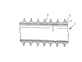
Figure 1 illustrates a ribbed pipe 1 manufactured
of polyvinyl chloride and comprising a pipe wall 2. The
inner face of the wall is smooth, while the outer face
thereof is provided with mutually spaced ribs 3
extending in the direction of the periphery. The ribs 3
are preferably ring-shaped.
Figure 2 illustrates the preferred embodiment of
the invention on an enlarged scale. According to the
invention an elevation 4 is provided on both sides of
each rib 3, which elevation extends over the whole
length of the rib and joins the side wall of the rib at
a sharp juncture line 5.
The elevations 4 are integral with the pipe wall
2 and the ribs 3, being formed simultaneouslv with the
other parts of the pipe. An outer face 6 of the
elevations, which face is adjoined to the side wall 7
of the rib, is inclined with respect to the outer face
of the pipe in such a manner that the distance thereof
from the outer face increases in a direction away from
the rib. By virtue of this inclination, a notch is
provided between the faces 6 and 7, which notch makes
it more likely that the rib will be fractured at the
juncture line 5. The angle between the faces 6 and 7
is, as appears from Figure 2, smaller than 90. A face
.
~3 267(~1o97
8 of the elevation joins the outer face of the pipe
smoothly so that a supporting surface as wide as
possible is provided for the rib 3.
Tests carried out show that a suitable radius
of the rounding of the junctu:re 5 is at the most about
10 per cent of the thickness of the rib 3, in practice
usually between 0.1 and 0.5 mrn, preferably about 0.2 mm.
The greatest height b and width c of the elevations 4
are preferably about half of the thickness a of the rib,
i.e. in practice usually about 2 mm.
In view of the operation of a pipe manufacturing
machine, it is desirable that the thickness a of the
ribs 3 increases towards the wall of the pipe. On the
contrary, it is of advantage in view of the operation
of the pipe according to the invention that the
inclination of the side walls 7 of the rib with respect
to a plane extending transversely to the pipe wall does
not exceed 3. It is also desirable in view of the
operation of the invention that the free end 9 of the
rib has a semi-circular cross-section.
Figure 3 illustrates a second embodiment of the
pipe according to the invention. It differs from the
embodiment of Figure 2 in that the outer face 6 of the
elevation 4 extends from the side wall 7 of the rib to
the outer face of the pipe wall in a roughly planar
form so that the angle between the faces 6 and 7 is
obtuse. In spite of this, the present embodiment, too,
operates in a manner according to the invention, since
the juncture line 5 is sharp, i.e. the radius of the
rounding thereof is very small.
Figure 4 illustrates an intermediate form of the
embodiments described above; the outer face 6 of the
elevation extends therein in parallel with -the pipe
wall 2 so that the angle between the faces 6 and 7 is
90. In this case, too, the juncture between the faces
is sharp.
3L26~ 37
When the pipe according to the invention is
exposed to an impact in the sideward direction, a
usually curved fracture surface is formed in the ribs
3, which receive the impact, the deepest point of the
fracture surface being positioned in level with the
juncture 5, from which the surface extends along a
curved line upwards up to the outer end of the rib.
Because the fracture surface does not usually extend
up to the inner face of the pipe wall, no point of
lea~age is formed in the pipe.