Language selection

Search

Patent 1267105 Summary

Third-party information liability

Some of the information on this Web page has been provided by external sources. The Government of Canada is not responsible for the accuracy, reliability or currency of the information supplied by external sources. Users wishing to rely upon this information should consult directly with the source of the information. Content provided by external sources is not subject to official languages, privacy and accessibility requirements.

Claims and Abstract availability

Any discrepancies in the text and image of the Claims and Abstract are due to differing posting times. Text of the Claims and Abstract are posted:

  • At the time the application is open to public inspection;
  • At the time of issue of the patent (grant).
(12) Patent: (11) CA 1267105
(21) Application Number: 542040
(54) English Title: REAR PLATFORM LIFT
(54) French Title: ELEVATEUR POUR PLATE-FORME ARRIERE
Status: Deemed expired
Bibliographic Data
(52) Canadian Patent Classification (CPC):
  • 201/9
(51) International Patent Classification (IPC):
  • B65G 67/02 (2006.01)
  • B65G 69/24 (2006.01)
(72) Inventors :
  • STURTZ, CHARLES R. (United States of America)
(73) Owners :
  • FMC CORPORATION (United States of America)
(71) Applicants :
(74) Agent: SIM & MCBURNEY
(74) Associate agent:
(45) Issued: 1990-03-27
(22) Filed Date: 1987-07-14
Availability of licence: N/A
(25) Language of filing: English

Patent Cooperation Treaty (PCT): No

(30) Application Priority Data:
Application No. Country/Territory Date
909,813 United States of America 1986-09-22

Abstracts

English Abstract


Abstract of the Disclosure
An aircraft loader has an elevatable deck supported on
scissor-type supports and urged into the elevated position by a
hydraulically actuated lifting structure. The lifting structure
incorporates two supports that move vertically on chain members when the
cylinders are actuated.


Claims

Note: Claims are shown in the official language in which they were submitted.


What is claimed is:
1. In an aircraft loader having an elevatable platform section
an improved hydraulic lifting means comprising:
a first movable transverse support having a pair of support
guide means mounted at outboard ends of said first transverse
support;
a second movable transverse support having a plurality of
hydraulic cylinders mounted thereto including a pair of hydraulic
cylinders, each of said pair mounted for vertical displacement at
outboard ends of said second transverse support, and a single
hydraulic cylinder having a piston rod end mounted for vertical
displacement in the center of said second movable transverse
support, said pair of hydraulic cylinders having piston rod ends
mounted to said first movable transverse support,
first flexible support means carried on said piston rod end
of said single hydraulic cylinder of said second transverse support,
said flexible support means having one end thereof fixedly connected
to said second moveable transverse support and a second end of said
flexible support means fixedly connected to said elevatable platform;
second flexible support means guided by said pair of
support guide means of said first transverse support, said second
flexible support means having one end thereof grounded to said
aircraft loader and having a second end thereof fixedly mounted to
said second moveable transverse support;


guide frame means carried by said aircraft loader for
guiding said transverse supports as they move vertically upon
actuation of said first pair and said single hydraulic cylinder.

2. The invention in accordance with Claim 1 wherein said
support guide means are flanged wheel pulleys mounted for rotation
around a horizontal mounting means on the lower side of the outboard
ends of the first movable transverse support.

3. The invention in accordance with Claim 2 wherein said first
movable transverse support is provided with a bore in the central
portion thereof, said bore provided to accommodate said single
hydraulic cylinder mounted to said second transverse support.

4. The invention in accordance with Claim 3 wherein said pair
of hydraulic cylinders are mounted to said second transverse support
with each of said cylinders fixedly attached to said second
transverse support.

5. The invention in accordance with Claim 4 wherein said
single hydraulic cylinder is fixedly mounted to said second
transverse support.

6. The invention in accordance with Claim 5 wherein said first
flexible support means is a chain.


7. The invention in accordance with Claim 5 wherein said first
flexible support means is a pair of chains each carried on said
piston rod end.

8. The invention in accordance with Claim 1 wherein each of
said hydraulic cylinders has a similar volumetric capacity.

9. The invention in accordance with Claim 1 wherein said
single hydraulic cylinder has a head end area larger than the head
end area of each of said hydraulic cylinders of said pair of
hydraulic cylinders.

10. The invention in accordance with Claim 1 wherein the
combined area of the ends of said pair of hydraulic cylinders is
greater than the head end area of said single hydraulic cylinder.


Description

Note: Descriptions are shown in the official language in which they were submitted.


~67~

Specif~cation
An aircraft loader Is a limited purpose vehicle used to load
cargo containers into aircraft. The loader must be capable of having a
deck elevated from a low level position to a high position whereby a
cargo container can be rolled off the loader deck into the cargo or
baggage hold of the aircraft being loaded.
The airline industry flys a plethora of aircraft designs, styles
and sizes. Each aircraft design requires a slightly d~fferent load
height as wetl as having different characteristics of suspension
deflection as the aircraft is belng loaded. Consequently, an aircraft
loader that can easily be positioned to match the height of the aircraft
being loaded is a desirab1e apparatus. Such aircraft loaders have been
in use for a number of years.
A new requirement, however, is the goal of providing a single
loader that can accommodate the side delivery of cargo conta~ner
requirements of various airlines. Not only are cargo containers of
different widths but they also may have to be turned on the a~rcraft
loader so that the container can be loaded into the aircraft in a ~anner
that is specified by the particular airline.

~ 43~


Earlier aircraft loader designs were hampered in operation and
maneuverability by the necessity of havlng tall upwardly extending masts
about one-third of the way back from the front of the loader. These
masts contained the lift actuating cylinders and attendant hardware and
were impediments to loading containers as they prevented containers
having a length greater than the distance between the masts from being
turned "widthwise" on the loader deck prior to the container being loaded
into the awa~ting aircraft.
The invention herein disclosed obviates the need for such
upwardly extending masts by providing a hoisting unit that remains below
the deck surface when the deck surface is elevated to an aircraft loading
height.
The invention will be readily understood after reading the
following specification in combination with the drawing figures wherein:
Figure 1 is a side elevation view of an aircraft loader with the
load deck raised.
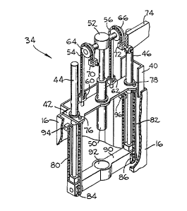
Figure 2 is a detail drawing of the hydraulic l~fting system of
the present Invention.
Figure 3 is a schematic representation of Figure 2.
Figure 4 is a sche~atic representation of Figure 2.
Figure 5 is a schematic representation of Figure 2.
Figurè 1 shows the general envlronment of the invention.
Presented is an aircraft loader generally 10 having ground support wheels
12 and 14 supporting a frame 16. At the front part of the vehicle an

~ 7'~4~


elevatable forward or deck platform 36 is supported for verticai movement
above a drive train compartment generally 22 of the aircraft loader. A
rear elevatable platform or deck 24 -is carried on the frame 16 and
supported on two sets of scissor beams 26 for movement vertically above
the frame 16.
In Figure 1 a cargo conta;ner, also referred to as cargo pallet
or cargo skid, 30 is shown in a position where it is awaiting transport
to the aircraft schematically shown as 32. The aspect of the aircraft
loader that is the inventive contribution is represented by the hydraulic
lift mechanism generally 34.
The hydraulic lift mechanism 34 is carried in the frame 16 of
the aircraft 10ader and is designed to elevate the rear platform 24 and
allow it to be lowered as necessary. It is significant that this lifting
apparatus 34 does not protrude above the rear deck surface when the rear
deck has been raised to meet with the forward deck 36.
While Figure 1 shows the general env-ironment of the lift
mechanisln generdlly 34, Figure 2 presents the details of the structure.
In Figure 2 the frame 16 is partially broken away to show the
lift mechanism but this frame does wrap around the lifting mechanism from
the left side of the figure to the right s;de thereof. Inside the frame
16 an extensible support 40 is carried for vertical movement in the frame
lfi. Although not shown in Figure 2 there is a mirror image extensible
support like 40 on the other (near) side of the lif~ mechanism -- it has
been left out of Figure 2 for reasons of clarity. Fixedly attached to

~ 7'~ ~ 5


both of these extensible supports is a movable transverse support
~referred to as a "second movable transverse support) which ~s a major
component of the lift mechanism.
This second movable transverse support hosts a plurality of
hydraulic rams including a matched pair of outboard hydraulic cylinders
44 and 46 mounted for vertical displacement at the outboard ends of the
second transverse support 42 and a single hydraulic cylinder 50 having a
rod end 52 mounted for vertical displacement in the center of the second
movable transverse support 42. The pair of outboard cylinders have their
cylinder portions f;xedly attached to the second movable transverse
support as does the single hydraulic cylinder 50.
Also fixedly attached to the second movable transverse support
42 are the grounded ends of the two first flexible support means 54 and
56 which are shown to be attached at clevisPs 60 and 62, respect~vely.
These flexible support means 54 and 56 can be chains that are carried on
the rod end 52 of the single hydraulic cylinder. The rod end 52 sho~n in
a preferred embodiment may have axle mo~lnted rollers such as 64 and 66
that accommodate the flexible support means 54 and 56. The second ends
of each flexible support means are attached by retainers 70 and 72 to a
frame component 74 of the rear elevator platform or deck 24.
The second movable transverse support 42 also provides a fixed
anchorage for the second ends 76 and 78 of the second flexible support
means 80 and 82. These second flexible support means 80 and 82 pass
around indiv;dual s(lpport gu;de means 84 and 86 which are flanged wheel

~ 7.~'5


pulleys mounted for rotation around a horizontal mounting means such as
an axle on the lower side of the outboard ends of a first movable
transverse support 90. The flrst movable transverse support 90 provides
a mounting location for the rod ends of the outboard cylinders 44 and 46
carried by the second movable transverse support 42. The second support
90 is also provided with a bore 92 in the central portion thereof to
accommodate the single hydraulic cylinder 50 mounted to the second
transverse support 42.
The first ends of the second flexible support means 94 and 96
are mounted by attachment means to the frame 16 of the aircraft loader
and thus are grounded and not movable.
Figures 3-5 are schematic representat;ons presented to show the
various stages of elevation tha~ are achieved by the lift mechanism as
tlle hydraulic cylinders receive fluid ~rom a pump source not shown ~ut
well known in the art. It should be clearly understood that these are
schematic representations of the general timing that the dev;ce shown ln
Figure 2 will cycle through, ho~ever, Figures 3-5 do not represent a
preferred embodiment of the invention. I~hereas Figure 2 shows the lift
device at almost full stroke, that is, almost fully extended, Figure 3
shows the lift mechanism schematically fully retracted. The firs~ end 94
of the second flexible~support means 80 is shown grounded to frame l6.
The second flexible support means 80 is carried around the support guide
means 84 and then the second end of the second flexible support means 76
is attached to the second movable transverse support 42. The first


--6--
movable transverse support is hidden behind the support guide means 84.
Both outboard matched cy1inders such as 44 are fixedly mounted to the
second movable transverse support 42 as is the single hydraulic cylinder
50.
The first of a pair of the first flexible support means 54 is
shown mounted at device 60 to the second movable transverse support means
42 while the other end is mounted at retainer 70 to the frame component
74.
In operation, starting at Figure 3 and progressing to Figure 5
the single hydraulic cylinder 50 will be pressurized causing its ram to
extend with the axle mounted roller 64 lifting the frame component 74 as
shown in Figure 4. In a preferred embodiment when this single cylinder
50 is fully extended hydraulic fluid flows will be diverted the pair of
outboard hydraulic cylinders 44 (and 46) causing its ram to extend and in
turn lift the first movable transverse support 90 vertically up~lard along
w;th the second movable transverse support 42 which will also be urged
upwardly at the same time. Upon full pressurization of all the cylinders
the frame component 74 and the rear deck bed will be at maximum height
(now shown). As fluid is exhausted from the cylinders the rear deck bed
will be gradually lowered until it is at rest on the frame 16 when
theoretically all the cylinders will be raised of pressure.
An alternative embodiment would have a hydraulic circuit supply
the single cylinder before the pair of outboard cylinders or vice-versa.
Also the hydraulic supply could be such that all cylinders raise and
lower at the same rate.


..


The sizing of the single cylinder SO relative to the aggregate
size of the outboard cylinders 44 and 46 will be one determining factor
in the rate of lift and the timing of cylinder actua~ion.
Thus it can be shown that there has been provided a hydraulic
lift system that enables a deck of an aircraft loader to be fully
elevatab1e without the attendant disadvantages of the prior art. Several
nuances of design may be apparent to a person skilled in the art,
however, such nuances are not to be construed to in any way lessen the
scope of the following claims~dl==e3~-


Representative Drawing
A single figure which represents the drawing illustrating the invention.
Administrative Status

For a clearer understanding of the status of the application/patent presented on this page, the site Disclaimer , as well as the definitions for Patent , Administrative Status , Maintenance Fee  and Payment History  should be consulted.

Administrative Status

Title Date
Forecasted Issue Date 1990-03-27
(22) Filed 1987-07-14
(45) Issued 1990-03-27
Deemed Expired 2000-03-27

Abandonment History

There is no abandonment history.

Payment History

Fee Type Anniversary Year Due Date Amount Paid Paid Date
Application Fee $0.00 1987-07-14
Registration of a document - section 124 $0.00 1987-09-28
Maintenance Fee - Patent - Old Act 2 1992-03-27 $100.00 1992-02-17
Maintenance Fee - Patent - Old Act 3 1993-03-29 $100.00 1993-02-25
Maintenance Fee - Patent - Old Act 4 1994-03-28 $100.00 1994-02-14
Maintenance Fee - Patent - Old Act 5 1995-03-27 $150.00 1995-02-10
Maintenance Fee - Patent - Old Act 6 1996-03-27 $150.00 1996-02-16
Maintenance Fee - Patent - Old Act 7 1997-03-27 $150.00 1997-02-12
Maintenance Fee - Patent - Old Act 8 1998-03-27 $150.00 1998-02-05
Owners on Record

Note: Records showing the ownership history in alphabetical order.

Current Owners on Record
FMC CORPORATION
Past Owners on Record
STURTZ, CHARLES R.
Past Owners that do not appear in the "Owners on Record" listing will appear in other documentation within the application.
Documents

To view selected files, please enter reCAPTCHA code :


To view images, click a link in the Document Description column. To download the documents, select one or more checkboxes in the first column and then click the "Download Selected in PDF format (Zip Archive)" or the "Download Selected as Single PDF" button.

List of published and non-published patent-specific documents on the CPD .

If you have any difficulty accessing content, you can call the Client Service Centre at 1-866-997-1936 or send them an e-mail at CIPO Client Service Centre.


Document
Description 
Date
(yyyy-mm-dd) 
Number of pages   Size of Image (KB) 
Representative Drawing 2001-10-05 1 16
Drawings 1993-09-18 2 60
Claims 1993-09-18 3 75
Abstract 1993-09-18 1 10
Cover Page 1993-09-18 1 19
Description 1993-09-18 7 220
Fees 1997-02-12 1 56
Fees 1996-02-16 1 63
Fees 1995-02-10 1 32
Fees 1994-02-14 1 22
Fees 1993-02-25 1 19
Fees 1992-02-17 1 19