Note: Descriptions are shown in the official language in which they were submitted.
~2~i o ~
PATENT
Docket ff7098-CAN
_ STENER FOR GROUND E~ COVER5
_I~MARY OF THE ~ Q~
This invention relates to a machine for implanting
fastener elements down through a cover on the ground, particular-
ly a fabric cover for grass seedlings on sloping ground.
A common practice i 5 to lay erosion cloth over grass
seedlings, partieularly on sloping ground borderin~ roads and at
highway interchangesA The erosion cloth is a fabric cloth
designed to hold seeds in the ground and to hold in place mu1ch
products that cover seed in the ~round to foster seed germina-
tion and growth of seedling roots through the top layer of soil.
The erosion cloth must be fastened in place in the ground so
that ft will not be displaced from the desired location by rain,
water runoff or wind.
To hold the erosion cloth in place, the usua1 pract~ce
has been to use a hammer which drives hand held staples down
through the erosion cloth an~ into the ground. Typically. not
~ore than about 200 staples per hour can be inserted by a person
using such methods and the user must be on his hands and knees or
bent over to operate the hammer.
~'
.:~
.
, ~ :
The present invention is a foot-operate~ fastener
implanting machine which overcomes these difficul-ties because the
user can stand erect7 or substantially so, while operating -the
implanter and can cover more ground without fatigue.
A principal object of thi 5 invention is to provide a
novel ~oot-operated machine for implanting fastener elements down
through erosion cloth on the ground.
Further objects and advantages of this invention will be
apparent from the following detailed description of two presently
preferred embodiments ~hich are illustra-ted schematically in the
accompanying drawings.
DESCRIPTION OF THE DRAWINGS
Figure I is a side elevation of a fir~t machine
according to this inven-tion;
Figure 2 is a rear elevation of thi 5 machine;
Figure 3 is a front elevation;
F~gure 4 is a bottom plan view7 taken from the line
4~-4 in Figure l;
Figure 5 is a perspective view of one of the fastener
elements used in the machine o~ Figures 1-4;
Figure 6 is an enlarged view taken from the front and
showing the 1ower two-thirds of the machine partly in elevation
and partly broken away to expose working parts;
,~
,,.
. .
~', . ' .
.
~: . ..
:
' ~ , . :
~L2$~
Figure 7 i 5 a vertical section taken along the line
7--7 in Figure 6;
Fi9Ure 8 i5 a view similar to Figure 6 with more par-ts
broken away to e~pQse additional work ing parts of the machine;
Figure 9 i 5 a side view of the lower Part of the
machine with the housin~ broken away to show the fastener
ma~azine;
Fi~ure 10 is a vertical cross-sec-tion taken along the
line 10--10 in Figure 9;
Figure 11 is a 1ongitudinal section taken along the
line 11--11 in Figure 10 at one side of the fastener elements in
the magazine:
Figure 12 i5 a top plan view, with parts broken away
for clari-ty, of a second embodiment of the present invention;
Figure 13 is a side elevation of the Figure 12 machine
with its fastener maga~ine taken apart 9
Figure 14 is a perspective view of a fastener used in
the machine of Figures IZ and 13;
Figure 15 is a side elevation of the maga7ine mechanism
in thi 5 machine;
Figure 16 is a vertical cross-section taken along the
line 16--16 in Figure 15; and
Fi~ure 17 shows a man operating either of the machines.
.
:: : , ~ ' . , :~
': ~: - .
:` ~
~ e~ore explaining the disclosed embodiments of the pre-
sent invention in detai1 it is to be understood that the inven-
tion is not limited in its application to the detail 5 of the
particular arrangements sho~n since the invention is capable of
other embodi~ents. Also, the terminology used herein i5 for the
purpose of de,cription and not of limitation.
DETAILED ~S~EIlQ~
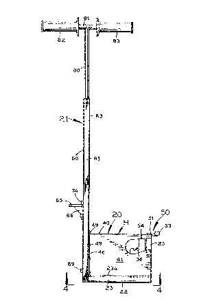
Referring to Figures l and 2. the implantin~ machine
shown there has a magazine assembly 20 at the bottom and a
~ertical column 21 extending up in front of the magazine assembly
and rigidly attached to it.
Referring to Figures 10 and i3, the maga2ine assemb1y
includes a magazine M having a bottom piece presenting a flat
botto~ wall 22 and vertical flanges 23 and 24 extendin~ up from
the bottom w~ll on OppO5 ite sides and terrninating at their upper
ends in respective inturned lips 23a and 24a. At the b~ck end ~f
the magazine (i.e., the end remote from the upstanding colu~n 21)
a ri~id end piece structure 25 ~Figure 13) extends vertically up
from the bottom wall Z2. There i 5 a slight clearance between each
int~rned lip 2~a and 24a o~ the botto~ piece and the adjacent
5 i de of the end piece structure 25.
The maga~ine has a pair o~ flat vertical sid~s 2~ and
27 (Fi ure 10) which extend up from its bottom wall 22 al~ng the
, . .. . . ..
'' '`' ': '' ~ '
.: ~
' :' ". '' ~ ~ '
entire length of the maga~ine from the back end piece structure
25 to its opposite front end. An upstanding front end wal1 28
(Figure 9) extends between and is joined to the sides 26 and 27
of the magazine at its front end. Both sides 26 and 27 have a
substantial clearance inward from the inturned lips 23a and 24a
of the magazine's bottom piece. Toward the front end of the
magazine its sides 26 and 27 rotatably support the horizontal
axle 29 of a pulley 30.
A follower P of generally channe1-shaped cross-section
is slidably mounted on the horizontally disposed top edges of the
sides 26 and 27 of the maga~ine. As shown in Figure 11, this
follower has a horizontal top wall 31, a depending side wall 32
extendin~ down from top wall 31 outside the adjacent side 26 of
the magazine, and a simi1ar opposite side wall (not shown) which
extends down from top wall 31 outside the adjacent side 27 of the
magazine. The side wall 32 of the follower has a vertical back
ed0e 33 extending down from its top wall 31. and a downwardly and
forwardly inclined edge 34 extending from the lower end of its
back ed~e and leadin~ to a downwardly-facing rounded notch 35.
The opposite side wall of the follower is a mirror image of side
wall 32t with a notch similar to notch 35. Toward the back end of
the magazine a cross pin 36 extends between its opposite sides 26
and 27 and projects outward past each of them for reception in
'~: ' ' '' ''
:; ' ~ , .
,
,.... :
..
::
"
-: :- ,
the notch 35 in side wall 32 of the -Fol10wer and the correspond-
ing notch in the opposite side wall of the follower. When these
notches in the fo1lower engage cross pin 36, as shown in phantom
in Figure 11. the follower P is held in its ~ully retracted
position rearward along the magazine.
As shown in Figure 9, a spring-anchoring screw 37
extends down from the top wall 31 of follower P at its back end
midway between its depending opposite sides, such as side 32. A
helically wound tension spring 38 is anchored at its upper end on
screw 37 and extends forward from it between the opposite sides
26 and 27 of the magazine, around the front of the pulley 30,
and from beneath this pulley back to a lower anchor provided by
cross pin 39, which i5 carried by the back end piece structure 25
of the magaz1ne, as indicated in Figure ll. This spring urges the
follower P forward (i.e., to the left in Figures 9 and 11) along
the top of the maga~ine.
The magazine is slidably engageable with a three-sided
rectangular magazine housing H (Figures IZ and 13) having a flat
horizontal top wal1 40 and opposite vertical side walls 41 and
42 extending down from the top wall. The housin~ side wall 41 is
spaced outward from the corresponding side 26 of the magazine,
as shown in Fi~ure lO, and the other housing side wall 42 is
similarly spaced outward from the corresponding side Z7 of the
: ~,
, 6
,. .~, . . .
:
, -,
,:
' ',';:, :
:
"~ ~
- -. : -
maga~ine. The lower end of the housing side wall 41 passes with
a slight clearance inside the inturned lip 23a on the bottom
piece of the maga~ine. Similarly, the lower end of the housing
side wall 42 passes down inside the inturned lip Z4a on the
bottom piece of the magazine. A vertically short, hori 20nta 11y
elongated p1ate 43 of rectangular cross-section is rigidly
attached to the outside of the housing side wall 4I just above
its bottom edge. This plate is s1idably received between the
bottom wall 22 and the inturned lip 23a at the inside of the
upstanding flange 23 on the bottom piece of the magazine.
Similarly, an identical plate 44 on the outside of -the other
housing side wall 42 is slidably received between the bottom
wall 22 and the inturned lip 24a just inside the upstanding
flange Z4 on the bottom piece of 'the maga2ine. With this arrange-
ment, the housin~ and the magazine can be slidably assembled
to~ether (Figure 1~ or slidably separated from one another
~Figure 13) when the user wants unobstructed access to the maga-
zine~ such as for inserting fastener elements in the magazine.
At its front end the magazine housing has a flat
transver~e peripheral flange with a top segment 45 ~Fi~ure IO)
and downwardly extending opposite side segments 46 and 47 which
are joined respectively ;to the top wall 40 and the side walls 41
and 4Z of the housing. The front end flan0e on the houslng is
formed with holes 48 for receiving bolts 49 for attachin~ the
magazine housing H to the back of the vertical column Zl.
'~
--
., '`, `
~,
~7~
At its back end the ma~azine housing H carries a latch
50 (Figures 11 and 12), preferably of spring steel. This latch
has a flat front segment 51 overlying the top wall 40 of the
mayazine housing and attached to it by rivets R, bolts or other
sui-table fasteners. The front segment 51 is joined to a short
downwardly extending segment 52 which7 as shown in Figures 9 and
11, eng3ges the Dack face o~ the back end structure 25 of the
magazine at the top when the magazine is fully inserted in the
magazîne housing. A looped handle segment 53 of the latch extends
rearward from the lower end of its vertical segment 5~.
Whenever the user wants -to remove the magazine from
the magazine housing, he lifts up the handle 53 until the verti-
cal segment 52 of the spring latch is disengaged from the back
end structure 25 of the magazlne and is above it. This releases
the latching engagement between the magazine housing H and the
magazine M. enabling the ma~azine to be slid rearward out of its
housing to the pO5 ition shown in Figure 13.
As shown in Figures I and 13, the magazine housing has
an opening 54 in each side extendin0 forward from i-ts back end.
Each o~ these openings enables the user to reach in and engage
the follower P to release it from the cross pin 36 on the maga-
zine.
" ~
~ . ,: . , .
~: . ' :'''': ,
:
:: ::
~ : ,
,.
Fi~ure 5 shows one of the fastener elements F used in
this machine. This faste~er has a thin but substantially rigid,
elongated vertical leg 55 having a tapered se~ment 56 at its
lower end to facilitate its insertion in the ground. The upper
encl of the vertical leg 55 is joined to one end of a horizontal
top segment 57. A shorter second vertical leg 58 extends down
from the opposite end of the top segment 57~ para1lel to the long
vertical leg 55. The entire fastener element is relatively thin
but substantially rigidv with opposite flat major faces. Many of
these fastener elements can be glued together face-to-face for
ease of handling but the ~lue is not ~trong enough to prevent the
separation of the forward-most Fastener element from the ones
behind it when the machine is operated to drive the Forward-most
~astener element down into the ~round.
To io3d the fas-tener elements in the magazine the
magazine is removed from its housing (Figure 13) and the glued
together assembly of fastener elements is 51 id onto the magazine
from its front end. The follower P at this time is locked in its
retracted position by th~ engagement of its notches 35 with the
cross pin 36 on the magazine. This stretches the tension spring
38. As shown in Figure 10, the spacing between the lon~ and short
Yertical le~s 55 and 58 of each fastener element is just slightly
greater than the spacing between the outer faces of the 5 i des 26
and 27 of the maga2ine~ so that the ~astener e1ements fit snugly
: ".
~ : '' -.. : ~
:; ~ ~ ,, ", ,, '
: -. :
, :, ~,
but slidably over the top of the magazine. The longer vertical
leg 55 of each Fastener extends down almost to the bottom wall 22
of the magazine.
After the magazine has been loaded with fastener
elements it is slid forward (to the left in Figure 13) into its
housing H until the spring latch 50 on the housing snaps down
behind the back end structure 25 of the magazine. as shown in
Figure Il. This locks the maga~ine inside the housing.
The user now can reach in through the housing openin~
54 to lift the fol10wer P up off the cross pin 36, 50 that the
follower now exerts a Forward push on the fastener elements ~due
to the tension spring 38) and the follower can move forward as
successive fastene!- elements are driven in~o the ground.
The vertical column 2I in front of the maga~ine
assembly is oF hollow rectangular cross-section ~Figure 4),
presenting a Flat vertical front wall 60, flat vertical opposite
side walls 61 and 62, and a flat vertical back wall 63 to which
the front end flange 45. 4~, 47 of the magazine housin~ H is
bolted. Inside this flange the back wall 63 of the colu~n has a
rectangular, vertically elon~ated openin~ 64 ~Figures 4 and l1)
which is large enough to pass the fastener elements F from the
ma~azine into the ho110w interior of the verti~al column 2I.
"~
. : :
, :: ,:.: '
, : '' ':',:, , : ,,
'
.:' ' ,~
:
:~ `
.
~7~
At the front of the vertical column 2I, a foot peda1
65 (Figures I and 3) is rigidly attached to the top of a 51 ide
66, which is slidably received in a vertica1ly extending s1Ot 67
in the front wall 60 of the columnO The width of the slot 67 is
~just slightly grea-ter than that of the slide 66 so that the
slide is substantially limited to vertical movement along the
slot. The 5 lide 66 is rigidly welded to or formed integral with
a vertically reciprocable member 68 ~Figure II) disposed in the
hollow interior of column 2I. A plate 69 welded to the front
wall 60 of the column at the lower end of slot 67 and a bottom
piece 70 on the inside of the front wall oF the column provide
downward limit stops for the s1ide 66 and the vertically recipro-
cable member 68 7 respectively.
Several inches above the uPper end of slot 67 in the
front ~all 60 of vertical column 2I, a cross pin 71 (Fiyures 2, 3
and lI) extends between and is rigidiy supported by the front
and back walls 60 and 63 oF the column. A grooved pulley 7~ is
rotatably mounted on this cross pin. A helîcally wound sprin~ 73
extends over the top of pulley 72 (Figure 6) and has its
opposite ends connected to the top piece 68a of reciproc~ble
member 68, as shown in F~gure 7. This spring is under tension
and it biases the unït~ry assembly of reciprocable member 68,
slide 66 and foot pedal 65 upward. In this position the foot
, ~, :
, . ~ :: :
.
, '.
~,
:.:
,~
. ~ ,
pedal 65 abuts a~ains-t a p1ate 74 ~/elded to ~he front wa11 ~0 of
the housing at the upper end of slot 67, 50 that plate 74 acts
as an upper limit stop.
When the user places a foot on top of the foot pedal
65 and pushes down, the unitary assembly of reciprocable member
68, slide 66 and the foot pedal i~ moved down~ overcoming the
upward bi~s exerted by spring 73.
As shown in Figure 4, two guide pieces 75 and 76 of
generally l_-shaped cross-section are rigidly attached to the
inside face of back wall 63 of vertical column 21. These guide
pieces extend cn opposite sides of the opening 64 in back wall
63 for the full height of that opening. In its side toward the
ma~a~ine assembly. guide piece 75 presents a shallow flat recess
77 which is of uniform width and depth for the entire height of
thi 5 gu ide piece. Similarly. the other guide piece 76 has a
recess 78 ~hose bottom face lies in the same vertical plane as
that of the bottom face of recess 77. ~oth recesses 77 and 7B
are open along the nei~hborin~ sides of the ~uide pieces 75 and
76. The vertica1 plane of the bottom faces o~ recesses 77 and 7
i5 spaced from the inside face oF the back wall ~3 of column 21
jU5t 51 ightly more than the thickness of a sin~le fastener ele-
ment F and less than the combined thickness of two of the fas-
tener elements glued together. The coplanar bo-ttom faces of
recesse~ 77 and 78 are exposed to the openiny ~4 in the back wall
"J 12
; ~
. ': '
- . , -
: , ~
;
..
~3 of column ?1. This back wall has a thickness slightly greater
than the thickness of a sin01e fastener element F.
A driver in the form o~ a rigid thin ~lat plate 79 is
rigidly attached by bolts B to the back of the vertically
reciprocable member ~8. This plate slidably engages the inside
face o~ the back wall 63 of vertical column 21 9 as shown in
Figure 7, and its thickness is such that it can pass snu~ly but
slidably down and up alsn~ the recesses 77 Ind 78 in guide
plates 75 and 76, as shown in Figures 4 and ~.
A ~ertical post 80 is ri~idly attached to column ~1 at
the latter's upper end and extends up from it. A horizontal
cross piece 81 on the upper end of post ao receives a pair of
cushioned hand grips 82 and 83.
In operation? spring 73 normally pulls up the ri~id
assembly of driver 79, ver-tically reciprocable member 68. slide
65 and foot pedal 65 to the upwardly retracted position shown in
Figure 9. The spring-actuated follower P in the magazine assembly
pushes the entire ~roup of fastener elements F to the left in
Fi~ure 9. The leading fastener element F abuts against the bottom
~f recesses 77 and 78 in guide plates 75 and 76. respectively~
and it is completely past the front end of the magazine. The
fas-tener element immediately behind the leadin0 one is positioned
in ~he opening 6~ in the back wall of column 217 substantially in
the plane ~f that wall.
,
13
.; , . ~ :
`;
.
: .
:
: :
.~ .
,.
~ ~ $ 3J~ 5
As shown in Figure 1/, the user can grasp the hand
grips ~2 and 83 and put one of his Feet on top of foot pedal 65.
When he pushes down on the foot pedalv the rigid assembly of the
foot pedal 65~ 5 lide 66, vertically reciprocable member 68 and
driver 79 moves down. The driver 79 engages the top of the
leading fastener element F, Forcing it down along the gui de
plate recesses 77 and 78 and driving its tapered lower end 56
first into the ground, followed by the rest of the fastener
element. The downwardly moving driver severs the leading
fastener elemen-t F from its glued connection to the followin~
one .
Figure 11 shQws the position of the parts at the
completion of driving one fastener element F into the ground
through an erosion cover C on the ground.
Th~ user now can remove his foot from the ~oot pedal
or relax its downward pressure on the foot pedal, 50 that the
return spring 73 can pull the foot ped~l 65~ slide 6~, vertically
reciprocable member 6~ and driver 79 up in unison to the
retracted, starting position shown in Figure 9.
As shown in Figure 17, the user can remain erect while
operating the machine, which reduces fatigue. Also, in this
standing position the user can move quickly and easily from one
fastening pO5 i tion on the ero~ion cover to the next. Conse-
qu~ntly, it is possible for the user in a given time period to
, 14
~:
'
: ~
~.~S~95
fasten a much larger area of the erosion cover on the gro~nd
than was po5s i ble by previously used techniques. A typical
worker can imp1 ant at least 5000 fastener elements per hour
using the present invention~ In addition, the machine i 5
entire1y man-powered. It does not require a vehicle either to
transport it from one fastening location to th~ next or to
provide power for the fastening operation.
Figure 14 shows a different fastener element than the
one shown in Fi0ur~ 5. It has an elongated central vertical leg
IOO and a pair of shorter vertical legs IOI and IOZ spaced from
the central leg and located on opposite sides of it. The vertical
legs are interconnecte~ by a cross-piece 103 3t the t~p. Thr~ugh-
~ut its extent this fastener is of thin but substantially riyid
construction, with flat opposite major faces.
Figures 15 and 16 show an implanting machine for use
with the fastener element shown in Figure 14~ Elements Qf this
machine which correspond to those of the maehlne shown in
Figures 1-4 and 5-13 are ~iven the same reference numeral 5 p 1 U5
IOO. so that the detailed description need not be repeated for
all of these elements. The upri~ht column and the vertica1ly
reciprocable implan-ting mechanism in it may be substantiaily the
same as shown in Figures 1-4, 6-8, IO and ll. The magazine
assembly in Figures 15 and 16 is different from the first embo~
diment because thP shape of the fastener element (Figure 14) is
different,
:,
,. .
'
~-
'
~$~
Referring to Figure 16, the magazine has a bottom
piece with a bottom wall 122 and ups-tanding flanges 123 and 124
on opposite sides which terminate at their upper ends in
inturned lips 123a and 124a. The magazine has opposite side
walls 126 and 127 extending vertically up from the bottom wall
122. The side ~alls are spaced apart enough to snugly but slid-
ably receive the elongated central verticai leg 100 of fastener
element~s. A series of these ~astener elements are glued face to-
face in succession~ as shown in Fi~ure 15. and 51 idably mounted
on the maga~ine.
Grooved pulleys 130a and 130h are rotatably moun-ted
on the outside o~ the upstanding side wal 15 126 and 127 of the
maga~ine, as shown in Fi~ure 16. A helic~lly wound tension spring
138a (Fi~ure 15~ extends around the front of pulley 130a. The
lower end of this spring i 5 anchored at 139a to the back ~nd
piece structure 125 of the ma~azine. The upper end of spring 138a
is attached to the follower P', which is slidably mounted on top
of the magazine. On the opposite side of the magazine, an identi-
cal spring 138b (Figure 16) extends around the front of pulley
130b and has its opposite ends connected respectively to the back
end piece structure IZ5 of the magazine and the follower pr.
Sprin3s 13~a and 13~b urge the follower P~ forward along the
maga~ine (i~e~, to the left in Figure 15~.
'
~ ...... ~
~: ' ' '' , ' '` ~ - ~.
'; :.',;, '
~' ' ' ' ::
~ ~4 ~9~
The magazine is slidably insertable into and removable
~rom a magazine housing H' similar to the housing H in the first
embodiment. The opposite sides 141 and 142 oF housing H' are
spaced from the corresponding sides IZ6 and 127 of the magazine
to pass the respective short vertical legs 101 and 102 of each
fastener. The top wall 140 of housing H' is spaced above the
horizontal top edges of the side walls IZ6 and 127 of the maga-
zine far enough to pass the cross-piece 103 at the top of each
fastener.
The operation of -this second embodiment is
essentially the same as the operation of the first embodiment7
already described in detail.
~ . .
.. - . :
.:
`
: . ,
,~