Note: Descriptions are shown in the official language in which they were submitted.
~ 2~J)~ ~ ~
l FOLDABLE PACKER HARROW IMPL,EMENT
Background of the Invention
1. Field of the Invention
The present invention relates to an agri-
cultural implement having a plurality of soil packer
units which are each positioned ahead of a respec-
tive, independent harrow assembly.
2. Description of the Prior Art
Compaction of soil around newly planted
seed has long been known to substantially increase
crop yiel~. In the past, soil compaction has some-
times been provided by a number of relatively heavy
packing wheels mounted on a cultivator, but unfor-
tunately the packing wheels may cause a substantial
amount of stress to be imposed on frame members of
the cultivator, and the wheels may also present
problems duriTlg transpor-t. Certain cultivators have
springs to apply force to the packer wheels, but
uneven depth control of the cultivator may occur
when the weight of the cultivator is less than the
forces imposed on the packer wheels.
In recent times, increased interest has
been directed toward the concept of soil compaction
by means of a series of coil packers coupled to the
trailing ends of harrow assemblies. Examples of
these types of harrow packer units are shown in U.S.
Patent No. 4,418,762 and Canadian Patent Nos.
838,417, 871,991, 1,081,021, 1,099,566, and
1,212,569~ The coil packer creates a herringbone
pattern on the ground which, according to some, is
useful for reducing wind and water erosion.
However, certain problems have been ob-
served in connection with the herringbone pattern
~6~,'3:~
1 left in the soil after use of a harrow packer unit.
In particular, water uptake by the soil is decreased
once the sidewalls of the herringbone packer tracks
become hard and crusted, and evaporation losses are
increased upon formation of puddles in the tracks.
Existing soil moisture may be readily lost due to
capillary action within the crusted, packed soil of
the tracks which is directly exposed to the atmo-
sphere. Also, the wave-like herringbone pattern
increases the total exposed surface area of the
field, which causes a corresponding increase in
total evaporation losses. Moreover, water runoff is
more likely to occur in packed grooves than might
occur, for instance, in loose soil.
Other problems that have been observed
with regard to harrow packer units include the
tendency for the coil packers to reintroduce weeds
into the ground that have previously been uprooted
during airseeding or during harrowing, thereby
encouraging the weeds to continue to grow and com-
pete with the crop. In addition, harrow packer
units tend to leave finely crushed soil on the top
surface of the ground where it is susceptible to
erosion by wind and water.
In some harrow packer units, coil packers
are arranged in staggered disposition relative to
the normal direction oi travel of the implement. In
this manner, the width of each coil packer can be
increased in an attempt to eliminate missed areas of
the ground not subjected to the forces of the coil.
However, during relatively sharp turns, some areas
of the ground may be left untouched due to the large
distance between the coil packers and the axis of
turning movement of the implementO Also, such
~2i~
1 construction increases the cost of the coil packers
in proportion to the increased width of the same.
Another problem associated with harrow
packer units is due to the relatively complex and
expensive mechanism that is often provided for
foldin~ the unit into and out of an orientation for
transport. In these devices, arms supporting the
harrow assemblies are fixed to a transversely ex-
tending structural frame member which is selectively
pivotable about an axis parallel to its longitudinal
axis ~or raising the unit towarcl a folded orienta-
tion. However, the relatively heavy coils are
pivotally coupled by means of an elongated hitch to
the trailing ends of the harrow support arms, and
therefore relatively stiff structural members and
large hydraulic piston and cylinder assemblies are
needed for developing sufficient torque to overcome
the mome~t presented by the packer coils and raising
the arms toward a vertical orientation. In addi-
tion, the coil packers of the folded unit, beingsupported solely on one side of the harrow by the
now overlying pivotal connection, are free to sway
and thus present a somewhat unstable arrangement
during transport of the unit.
Furthermore, unfolding of the aforemen-
tioned harrow packing units requires skill and
closely timed operator coordination since the unit
must be advanced slowly at a creep speed as the
packers are lowered to the ground. Other problems
which are encountered in harrow packer units of this
type include the tendency of the packers and harrow
sections to bind during turns while the unit is in
its folded, transport orientation which may lead to
serious damage to the tines.
-- 3 --
1 Summary oE the Invention
Our present invention overcomes the prob-
lems noted above by provision of a packer harrow
implement having a number of packer units directly
coupled to a transversely extending frame member or
tool bar, with harrow sections carried behind the
packer units by elongated, arched carrier arms
extending over the packer units. Each of the packer
units is connected by means of short, pivotal links
to the frame member for up and down shifting move-
ment in substantial independence of the vertical
movement of the trailing harrow sections.
A number of important benefits are realiz-
ed by use of the present invention. By mounting the
coil packers ahead of the harrow sections, clumps
and clods of soil as well as trash are left on the
top of the ground, thereby functioning as a barrier
to prevent moisture loss through capillary action.
The clumps, clods, and trash reduce wind and water
erosion, and the trash cover enhances moisture
intake into the soil from rain and also facilitates
subsequent retention of the moisture. Weeds pulled
from the soil by the harrow tines are left on the
ground surface to die instead of being reintroduced
into the ground for additional growth as is observed
with conventional apparatus.
Advantageously, the location of the rela-
tively heavy packer units, in close, proximal rela-
tionship to the tool bar or frame member, greatly
reduces the moment developed during pivotal movement
of the frame member about an axis parallel to its
longitudinal axis to raise the packer units and
harrow sections toward an upright orientation for
transport. The moment developed is considerably
3~ less than the moment which occurs during lifting of
1 prior art harrow packer implements havin~ the packer
coils or drums located behind the harrow sections
and at some distance from the pivotal, transverse
structural frame member or tool bar. As such, the
size and strength of the structural members as well
as the hydraulic piston and cylinder assembly of the
present invention can be substantially smaller than
heretofore realized, thereby affording a significant
cost savings.
In preferred embodiments of the invention,
the short links interconnecting the packer units and
the frame members are movable toward a position of
firm, resting contact with the frame member when the
latter is pivoted for raising the packer units and
harrow sections toward their upright, transport
orientation. As a result, the weight of the packer
units when lifted toward a transport orientation
causes the lmits to be retained in secure engagement
with the frame members without oscillating or movin~
laterally as the implement is transported at rela-
tively fast speed. In addition, the elevation of
the packer UllitS when in the transport mode remains
relatively close to the ground so that the center of
gravity of the raised implement is significantly
lower than in prior art structures, thereby enhanc-
ing the stability of the assembly durin~ on or off
the road travel.
Moreover, the implement constructed in
accordance with the invention may be readily folded
or unfolded out of its transport orientation without
interference or tanglin~ between the packer units
and the harrow sections, inasmuch as the harrow
sections are at all times kept Ollt of contact with
the packer units. During unfolding, the implement
need not be advanced at a creep speed as is the case
~l ,2~
1 with foldable harrow packer implements which are
articulated between the harrows and the trailin~
packers. Moreover, since the harrow sections of the
present invention are located at a distance from the
pivotal frame member, the harrow sections may be
easily raised from the ground when pluRged without
interrupting the advancement of the implement or
raising the packer units away from the earth.
Another important aspect of the present
invention relates to the preferred construction of
the packer units which are in the form of a general-
ly helical coil. In particular, end regions of each
packer coil extend in directions somewhat different
than the remaining, major extent of the coil and
terminate at a location closely adjacent a portion
of a neighboring convolution, thereby shorteninR the
overall width of the packer unit, As a result, the
end~to-end clearance between adjacent packer units
may be decreased so that satisfactory soil compac-
tion is provided across the entire width of theimplement without the necessity of, for instance,
staggering the packer units to obtain full coveraRe
as is the case with certain conventional harrow
packer implements.
The coil packers, being located closely
adjacent the transverse tool bars or frame members,
offer excellent clearance in turns~ The coil pack-
ers are thereby also disposed at a relatively short
distance to any axis about which the implement is
turned, thus substantially eliminating the presense
of missed regions of the soil not subjected to
compaction. The packers and harrow sections do not
bind against each other and damage the tines. More-
over, the two coil packers which are located adja-
cent opposite transverse ends of the implement are
1 preferably somewhat shorter than the remainin~ coil
packers, so that the two endmost harrow sections
cover the tracks left by the field tires while the
tires function to provîde soil compaction in regions
outboard of the packer units.
Brief Description of the Drawings
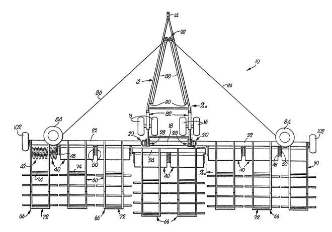
Figure 1 is a plan view of a packer harrow
implement constructed in accordance with the inven-
tion;
Fig. 2 is a fragmentary, enlarged, sideelevational view of the implement taken along line
2-2 of Fig. l;
Fig. 3 is a view somewhat similar to Fig.
2 except that transversely extending tool bars or
frame members of the implement have been pivoted to
raise the packer unit and harrow sections from the
ground;
Fig. 4 is a plan view of the implement
shown in Fig. 1 except that the harrow sections and
packer units have been raised and then folded to an
orientation for transport;
Fig. 5 is an enlarged, fragmentary plan
view of one of the frame members and packer units;
Fig. 6 is a fragmentary, enlarged, side
cross-sectional view of the frame member and packer
unit shown in Fig. 5 along with a portion of an
overlying, arched carrier arm for a trailing harrow
section;
Fig. 7 is an enlarged, fragmentary plan
view in partial section of one of the links for the
coil packer units shown in Figs. 1-6 which is con-
nected to a ball and socket coupling detachably
secured to one of the frame members; and
-- 7
~g.~
1 Fig. 8 is an enlarged, fragmentary, side
elevational view with parts broken away in section
of a pivotal interconnection between a wing frame
member and a main frame member of the implement
depicted in Figs. 1~7.
Detailed DescriE~n~ of~ the Drawings
An agricultural implement, broadly desig-
nated by the numeral 10 in Figs. 1-8, has hitch
structure 12 with a forward end portion 14 that is
depicted in Figs. 1, 3, and 4. The hitch structure
12 is supported by four parallel wheels 16, and the
forward end portion 14 of the hitch structure 12 is
adapted for connection with a towing vehicle (not
shown) that is movable in an advancement direction
over the ground and along a path of travel.
As best illustrated in Figo 1, the imple-
ment 10 has a main frame member 18 which is connect-
ed on each end by pivotal couplings 20 to an inboard
end of a respective wing frame 22. A center frame
member 24 is fixed to the main frame member 18 by
means of bars 26 that can be observed by reference
to Figs. 2 and 3.
Referring to Figs. 1-3 and 8, a pair of
bracket assemblies 28 are securely connected to
opposite end portions of the main frame member 18
and are each coupled by means of a pivot 30 (Figs. 2
and 3) to a trailing end of the hitch structure 12.
An outermost portion of each bracket assembly 28 is
pivotally secured to one end of a hydraulically
powered piston and cylinder assembly 32, the remain-
ing, forward ends of which are pivotally coupled to
upstanding legs 34 (Figs. 2 and 3) fixed to side
members oE the hitch structure 12.
~Z~'.'3~
l By comparison of Fi~s. 2 and 3, it can be
seen that simultaneous retraction of the pistons of
piston and cylinder assemblies 32 lifts the main
frame member 18 as well as wing frame members 22 and
center frame member 24 for swinging movement about a
horizontal axis coincident with pivots 30. Once the
frame members 18, 22, 24 have been shifted from
their use orientation shown in Fig. 2 to their
transport orientation illustrated in Fig. 3, a pin
connection (not shown) may be inserted through an
aperture 36 in the bracket assemblies 28 as well as
a corresponding aperture in an upstanding leg 38
affixed to structure l2 in order to releasably lock
the members 18, 22, and 24 in their transport orien-
lS tation.
Implement 10 further includes a number ofsoil packer units 40 which are disposed directly
behind a respective one of the frame members 22, 24.
Preferably, each of the packer units 40 is comprised
of a generally helically shaped coil packer 42 as is
shown in Figs. 1 and 5, although other types of
packer units such as crowfoot packers may also be
employed.
Each of the coils 42 is fixed on opposite
ends to bar-like supports 4~ (see, in this regard,
Figs. 5 and 6) which, in turn, are securely connect-
ed to a shaft 46 disposed along the central, lon~i-
tudinal axis of coil 42. End sections of the shaft
46 are received in respective bearings 48 that are
connected to trailin~ ends of short links 50, the
forward ends of which are fixed to a swivel or ball
and socket connector 52.
The ball and socket connector 52 is better
shown in Fig. 7, where it can be observed that a pin
3S 54 extends through a central bore in the connector
1 52 as well as aligned holes in opposecl legs of a
U-shaped bracket 56 that is fixed to a side of one
of the square-in-cross section wing frame members
22, although a similar arrangement is employed for
coupling the connectors 52 of the central coils 42
to the center frame member 24. The pin 54 is re-
leasably retained in place by means of a hairclip
58, so that the packer units 40 may be readily
detached from the implement 10 when desired.
A number of spaced, parallel carrier arms
60 are securely coupled to frame members 22, 24 and
extend rearwardly relative to the advancement direc-
tion of the hitch structure l2 in parallel relation
to the path of travel of the implement lO over the
ground. Each of the arms 60 has a raised or arched
section 62 that curves over and around the coils 42
therebeneath. A relatively short, elongated leg 64
is fixed to each of the arms 60 directly behind the
arched section ~62 in generally transverse relation
to the direction of extension o-f arms 60.
Each adJacen-t pair of the carrier arms 60
supports a leveling device for smoothing the soil.
In the particular embodiment illustrated in the
drawings, each leveling device is in the form of a
harrow section 66 coupled to the carrier arms 60 by
means of flexible strap means or chains 68, 70.
Chains 68 interconnect a mid-region of each harrow
section 66 and an end portion of each carrier arm
60, while chains 70 interconnect a forward region of
each harrow section 66 and lower regions of le~s 64.
Viewing Figs. l-3, each of the harrow
assemblies or sections 66 includes a rectan~ular
framework 72 having a transversely extending front
element 74 (FiR. l). Four parallel, spaced carrier
3~ pipes 76 are fixed to the underside of framework 72,
- 1 0 -
~Lf2~
l and each pipe 76 carries a number of slender, ~ield-
able spring tines 78 (Figs. 2 and 3).
I~hen the implement 10 is in its use ori-
entation as shown in Figs. 1 and 2, and 5-8, the
chains 68 are slack and the front chains 70 are
operable to pull the sections 66 in a forwardly
direction. However, as the frame members 22, 24 are
shifted about pivot 30 by means of piston and cylin-
der assemblies 32 to the transport orientation as
shown in Fig. 3, chains 68 function to limit the
extent of the downwardly shifting movement of the
harrow sections 66 and retain the same in proximal
relation to arms 60.
A better understanding of the couplings 20
interconnecting the wing frame members 22 and the
main frame member 18 may be obtained by reference to
Fig. 8. As shown, the coupli.ng 20 includes a pivot-
al connection 80 which allows independent, up and
down swin~ing movement of the respective wing frame
22 relative to the main frame member 18 when the
implement 10 is in its field or use orientation as
is shown in Fig. 1. Also, once the piston and
cylinder assemblies 32 have been retracted to pivot
the frame members 18, 22, 24 to their transport
orientation as is shown in Fig. 3, the two wing
frame members 22 are swingable about the now verti-
cally oriented pivotal connection 80 in a rearwardly
direction and toward the configuration as shown in
Fig~ 4 so that the implement 10 presents a relative-
ly narrow profile for transport. In this orienta-
tion, a second pivotal connection 82 of couplin~ 20,
disposed in offset, perpendicular relation to pivot-
al connection 80, enables up and down swingin~
movement of the win~ frame members 22 relative to
3~ the main frame member 18 and the hitch structure 12
~2~
l as a pair of transport wheels 8~ roll over the
ground.
As illustrated in Fig. l, a pair of wire
cables 86 are fixed to the front end of respective,
elongated bars 88 that are each coupled to a corres-
ponding side of the hitch structure l2 by means of a
pivotal joint 90. The remaining end of each cable
86 is connected to one of the wing frame members 22
in order to retain the la-tter in alignment with the
main frame member l8 as the implement lO is advanced
over the ground in its use orientation. A latch 92,
mounted on the forward end portion 14 of hitch
structure l2, is releasable to enable the bars 88 to
swing about respective Joints 90 for allowin~ the
wing frame members 22 to be shifted rearwardly
toward their folded, transport orientation shown in
Fig. 4. Each of the bars 88 is biased downwardly
toward their orientation as shown in Fig. l by means
of a spring (not illustrated) so that the cables 86
do not become entangled with remaining cornponents of
the implernent lO during folding or unfolding of the
latter.
It can now be appreciated that during use
of the implement lO, the short, pivotal links 50
directly interconnecting the coil packers 42 and the
frame members 22, 24 are shiftable up and down in
substantial independence of the movement of the
carrier arms 60. Moreover, the ball and socket
connectors 62 function to enable the orientation of
the packer coils 42, and particularly the central
axis of the coils 42, to tilt in either direction
slightly from horizontal in order to follow the
contours of the ground without affecting the posi-
tion or orientation of the respective trailin~
harrow section 66. The arched section 62 of the
1 carrier arms 60 provides sufficient clearance for
avoiding contact with the coils 42 therebelow as the
latter ride in complete freedom over large stones or
other obstacles in the field without damage to the
body of the coils 42.
Each of the coils 42 rolls smoothly over
the ~round during advancement of the implement lO to
roll and pack the soil and thereby enable the harrow
sections 66 to travel along a smoother path. In
addition, the trailing harrow section 66 smoothes
and levels the ground, pulls up weeds and leaves the
trash and coarse particles on the ground surface to
thereby reduce wind and water erosion and enhance
soil moisture retention, while also leaving the
weeds on top of the ground to die.
Upon completion of the work operation~ the
piston and cylinder assemblies 32 are retracted to
simultaneously raise the frame members 22, 24 and
the associated~packer units 40 and harrow sections
66 toward their upright, transport orientation as
shown in Fig. 3. At the same time, a portion 94
(Fig. 6) of each of the packer unit links 50 moves
toward a position of firm, resting contact with a
stop means or wall surface 96 (Fig. 7) which is
formed as part of the associated bracket 56. There-
fore, the relatively heavy coil packers 42, which
may, for example, weigh as much as a l50 pounds per
lineal foot, are securely supported by the respect-
ive frame member 22, 24 when lifted to a transport
orientation and do not shift or bounce during rela-
tively high speed road transport of implement 10.
Furthermore, it can now be understood that
the disposition of the packer coils 42, in forward
relation to the harrow sections 66, is highly advan-
tageous in that the mass of the packer coils 42 is
~2~
l retained at all times in close, proximal relation tothe supporting frame members 22, 24. Thus, the size
of the piston and cylinder assemblies 32 and
strength and stiEfness of the structural members
such as members 22, 24 is smaller than what would be
otherwise he necessary. The swinginR movement of
the links 50 toward the position shown in Fig. 3 in
contact with the wall surfaces 96 lowers the center
of Rravity of the implement lO somewhat in disposi-
tion closer to the Rround as well as the pivotalconnection 30 and the supporting wheels 16.
Finally, reference is made to Fig. 5 for a
more detailed understandin~ of the coil packers 42
of the present invention. Specifically, the coil
packer 42 is comprised of a body having a major,
central region 98 with convolutions extendin~ in a
direction inclined relative to reference planes
perpendicular to the lonRitudinal axis of packer 42
(which is coincident with the longitudinal axis of
shaft 46). The body also includes two opposed end
re~ions lO0 integrally connected to the central
region 98 and extending in respective, parallel
reference planes that are perpendicular to the
longitudinal axis of shaft 46. In this manner, each
of the coil packers 42 terminates at a location
closely adjacent one of the convolutions of the
major, central region 98, to thereby effectively
tuck the free ends of the coil packers 42 inwardly
and reduce the overall length of the same.
As a consequence, each of the coil packers
42 can be positioned in closely spaced, end-to-end
disposition relative to the remaininR coil packers
42 without leavinY~ a substantial area of uncompacted
soil as the implement 10 is advanced over the
Rround- Furthermore, the two endmost coil packers
~2~','3:~
l 42, located at the outboard end of each wing frame
member 22, are advantageously somewhat shorter than
the remaining coil packers 42 so that the trailing
harrow sections 66 are of a width sufficient to
cover the tracks left by field wheels 102 rotatably
mounted on the outboard ends of wing frame members
22. Moreover, by practice of the present invention,
the field wheels 102 are not damaged when the imple-
ment is folded to its transport orientation, in
comparison to certain of the conventional implements
where harrow sections and packer coils are in con-
tact with the field wheels during transport of the
implement.
IE desired, the implement 10 may be used
for smoothing the ground without compaction thereof
by removal of the hair clips 58 and pins 54 in order
to detach the packer units 40 from frame members 22,
24. As an alternative, one may wish to compact the
soil without use of the harrow sections 66 which can
easily be accomplished by disconnectin~ chains 6~,
70.
Although the foregoing represents a de-
tailed description of a currently preferred embodi-
ment of our invention, it is to understood in this
regard that various modiEications or additional may
be effected to the structure shown in the drawings
without departing from the gist and essence of our
contribution to the art. Accordingly, the invention
should be deemed limited only by a fair scope of the
claims which follow along with their mechanical
equivalents thereof.