Note: Descriptions are shown in the official language in which they were submitted.
3L~; 7~ L
F-4159
STIMULATION OF EARTH FORMATIONS SURROUNDING A
DEVIATED WELLBORE BY SEQUENTIAL HYDRAULIC FRACTURING
This invention relates to the hydraulic fracturing of an earth
formation and more particularly to a method of sequential hydraulic
fracturing of an earth formation surrounding a wellbore that is
substantially deviated from the vertical.
In the completion of wells drilled into the earth, a string of
casing is normally run into the well and a cement slurry is flowed
into the annulus between the casing string and the wall of the
well. The cement slurry is allowed to set and fonm a cement sheath
which bonds the string of casing to the wall of the well.
Perforations are provided through the casing and cement sheath
adjacent the subsurface formation. Fluids, such as oil or gas, are
produced through these perforations into the we11.
Hydraulic fracturing is widely practiced to increase the
production rate from such wells. Fracturing treatments are usually
performed soon after the formation interval to be produced is
completed, that is, soon after fluid communication between the ~ell
and the reservoir interval is established. ~ells are also sometimes
fractured for the purpose of stimulating production after
significant depletion of the reservoir.
Hydraulic fracturing techniques involve injecting a fracturing
fluid down a well and into contact with the subterranean formation
to be fractured. Sufficiently high pressure is applied to the
fracturing fluid to initiate and propagate a fracture into the
subterranean fonmation. Proppant materials are generally entrained
in the fracturing fluid and are deposited in the fracture to
maintain the fracture open.
Several such hydraulic fracturing methods are disclosed in U.S.
Patent Nos. 3,965,982, 4,0b7,389; 4,378,845; 4,515,214; and
4,549,608 for example. It is generally accepted that the local
in-situ stresses in the formation at the time of the hydraulic
3~
1~>~7~6:~L
F-4159 -2-
fracturing generally favor the formation of vertical fractures at
depths greater than about 2000 to 3000 feet.
In accordance with the present invention, oil and gas production
from a naturally fractured earth formation surrounding a deviated
wellbore is stimulated by sequential hydraulic fracturing.
Fracturing fluid is initially supplied to the formation at a first
depth within the deviated wellbore to propagate a f~rst vertical
fracture as favored by the original in-situ stresses of the
formation in a dlrection that is perpendicular to the least
principal in-situ stress, the formation of such vertical fracture
altering the local in-situ stresses~ Fracturing fluid is thereafter
supplied to the formation at a second depth within the deviated
wellbore, whi7e maintaining pressure in the first vertical fracture,
to propagate a second vertical fracture in a direction that is
parallel to the least principal in-situ stress as favored by the
a1tering of the local in-situ stresses by the formation of the first
vertical fracture, such that this second vertical fracture
intersects the naturally occurring fractures in the formation which
are perpendicular to the direction of the least principal in-situ
stress so as to link such naturally occurring fractures to the
wellbore and thereby stimulate the production of oil and gas from
the formation.
In a more specific aspect of the invention, casing is set in the
deviated wellbore and tubing is hung within thè casing to a depth at
which hydraulic fracturing is to be initiated, an annulus being
formed between the tubing and ~he casing. A packer is placed in the
annulus at a depth where the local in-situ stresses o~ the formation
favor the propagation of a vertical fracture. Upper perforations
are generated in the casing immemdiately above the packer. Lo~er
perforations are generated in the casing near the bottom end of the
tubing. Fracturing fluid is first supplied under pressure through
the annulus and out the upper perforations into the formation to
propagate the first vertical fracture through the formation in a
direction perpendicular to the least principal in-situ stress. The
it7;3
F-~59 -3-
propagation of this fracture alters the local in-situ stresses in
the formation. Fracturing fluid is then supplied under pressure
through the tubing and out the lower perforations into the formation
to propagate the second vertical fracture through the formation in a
direction parallel to the least principal in-situ stress as now
favored by the altered local in-situ stressesO
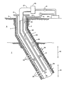
In the drawings, FIG. 1 illustrates apparatus associated with a
deviated wellbore penetrating an earth fonmation to be hydraulically
fractured in accordance with the present invention.
FIG. 2 is a pictorial representation of the vertical hydraulic
fractures formed in the earth formation surrounding a deviated
wellbore by use of the apparatus of FIG. 1.
The present Invention provides for a method for stimulating the
production of oil or gas from earth formations surrounding a
deviated wellbore by creating a vertical hydraulic fracture that
links naturally occurring formation fractures to the wellboreO
The direction of naturally occurring fractures is generally
dictated by tne in-situ stresses which existed at the time the
fracture system was developed. As in the case of hydraulic
fractures, these natural fractures form perpendicular to the least
principal in-situ stress. Since most of these natural frackures in
a given formation are usually affected by the same in-situ stress9
they tend to be parallel to each other. Very often, the orientation
of khe in-situ stress that existed when the natural fractures were
formed coincides with the present in-situ stress. This presents a
problem when conventional hydraulic fracturing is employed. For
example, a vertical hydraulic fracture created in a naturally
fractured for~ation generally propagates parallel to the direction
of the natural fractures. This results in only poor communication
between the wellbore and the natural fractures and does not provide
for optimum oil or gas production.
The present invention is intended to solve this problem by a
hydraulic fracturing technique in which the vertical hydraulic
fracture is propagated in a direction perpendicular to the naturally
~2673~
F-4159 -4_
occurring fractures so as to link them to the wellbore and greatly
enhance or stimulate the production of oil or gas from the naturally
fractured formation. This technique can best be understood by
reference to FIGS. 1 and 2.
Referring first to FIG. 1, there is shown formation fracturing
apparatus with which the hydrau~ic fracturing method of the present
invention may be carried out. A deviated wellbore 1 generally
exceeding 60 deviation from the vertical, extends from the surface
3 through an overburden 5 to a productive formation 7 where the
in-situ stresses favor a vertical fracture. Casing 11 is set in the
wellbore and extends from a casing head 13 to the productive
formation 7. The casing 11 is held in the wellbore by a cement
sheath 17 that is formed between the casing 11 and the wellbore 1.
The casing 11 and cement sheath 17 are perforated at 24 and at 26
where the local in-situ stresses favor the propagation of vertical
fractures. A tubing string 19 is positioned in the wellbore and
extends from the casing head 13 to the lower end of the wellbore
below the perforations 26. A packer 21 is placed in the annulus 20
between the perforations 24 and 26. The upper end of tubing 19 is
connected by a conduit 27 to a source 29 of fracturing fluid. A
pump 31 is provided in communication with the conduit 27 for pumping
the fracturing fluid from the source 29 down the tubing 19. The
upper end of the annulus 20 between the tubing 19 and the casing 11
is connected by a conduit 37 to the source 29 of fracturing fluid.
A pump 41 is provided in fluid communication with the conduit 37 for
pumping fracturing fluid from the source 29 down the annulus 20.
In carrying out the hydraulic fracturing method of the present
invent~on with the apparatus of FIG. 1 in a zone of the formation
where the in-situ stresses favor a vertical fracture, the pump 41 is
activated to force fracturing fluid down the annulus 20 as shown by
arrows 35 through the perfonmations 24 into the fonmation as shown
by arrows 36 at a point immediately above the upper packer 21. The
in-situ stresses at this point that favor a vertical fracture are
shown in the example of FIG. 2. A least principal horizontal stress
(ahmin) may be about 12100 kPa (175Q psi) and a maximum principal
~;~67~363~
F-4159 ~5~
in-situ horizontal stress (ahmax) may be about 12~00 kPa (1850
psi). For this example, a fluid pressure of 14800 kPa (2150 psi)
may be maintained during thP initial propagation of a vert~cal
fracture 42 that is perpendicular to the direction of the least
principal in-situ stress ahmin by controlling the fracturlng fluid
flow rate through annulus 20 or by using well known gelling agents.
Due to the pressure in the vertical fracture 42, the local
in situ stresses in the formation are now altered from the original
stresses to favor the formation of a vertical fracture that is
parallel to the least principal in-situ stress uhmin. Such a
vertical fracture 43 can thereafter be formed in the formation by
activating the pump 31 to force fracturing fluid down the tubing 19
as shown by arrows 38 and through the perforations 26 into the
formation as shown by arrows 39 at a point near the bottom of the
wellbore. This second vertical fracture 43 is propagated while
maintaining the fluid pressure on the first fracture 42, which can
either be stabilized in length or still propagating.
In the example of FIG. 2, the penetration of the second vertical
fracture 43 is in the order of 73 m (240 feet) from the plane of the
first vertical fracture 42. If the pressure in the first fracture
42 were maintained at 22100 kPa t3200 psi), for example, instead of
14800 kPa (2150 psi), then the second fracture 43 would be extended
in the order of 73 additional meters (240 additional feet) from the
plane of the first fracture 42 as shown in FIG. 2 as the extended
second fracture 43a. This penetration of the second fracture 43 and
extended second fracture 43a is relative to that of the first
fracture 42. If the penetrations or lengths of the wings of the
first fracture 42 are doubled from 36 m (120 feet) to 73 m (240
feet), for example, then the penetrations or length of the second
fracture 43 and its extension 43a are doubled from 146 m t480 feet)
total to 293 m t960 feet) total, for example.
Instead of initiating the vertical fracture 42 above the
vertical fracture 43 as described above and as shown in FIG. 2, the
fracturing fluid could be firstly pumped down tubing 19 and out
~L;~ti 7;~
F-4159 -6-
perforations 26 to form the vert~cal fracture 42 near the bottom of
the wellbore and thereafter pumping the fracturing fluid down the
annulus between the casing 11 and tubing 19 and Ollt per~orations 24
to initiate the vertical fracture 43 above the vertical fracture 42.
Having now described a preferred embodiment for the method of
the present invention9 it will be apparent to those skil1ed in the
art of hydraulic fracturing that various changes and modifications
may be made without departing from the spirit and scope of the
invention as set forth in the appended cla~ms. Any such changes and
modifications coming within the scope of such appended claims are
intended to be included herein.