Note: Descriptions are shown in the official language in which they were submitted.
y~
SEALING ARRANGEMENT FOR AIR PREHEATER
. .
: ~AC~GRO~ND OF THE INVENTION
~ 1~ Technical Fi~ld of th~ Disclosure
. _ _
The present invention relates to regenerative air
S preheaters and particularly to improved radial and circumfer-
enti.al sealing arrangements for ef~ecting seals between the
.
relatively movable portions of the air preheater, namely, the
drum~containing the matrix of heat exchanging elements and
the surrounding housing.
..
2~ Descri~tion of the Prior Art
It i~ typical in fuel burning installations or
devices, such as elec~ri~al power generating plants, to use
regenerative air preheaters for heating the intake air to
improve the efficiency of the ~uel burning operation. These
~,
: ' :
air preheaters typically include two major components, name-
ly, a generally cylindrical drum having a matrix of heat ex-
changing elements therein and a surrounding housing having a
generally cylindrical opening therein. One type of preheater
has a stationary drum and a movable housing surrounding the
drum. However, the most commonly used preheaters are those
of the Lju ~trom type in which the drum is a cylindrical ro
tor containing metallic heat transfer plates, the rotor being
movable with respect to a surrvunding stationary housing. As
the rotor turns, the heat transfer plates are first exposed
to hot discharge gases, and these heated plates then move in-
to the air intake passage to heat the incoming air. The hous-
ing surrounding the drum includes sector plates which divide
the housing into an air intake half and gas discharge half.
In an attempt to reduce the mingling of the two fluids, the
drum is typically provided with radially extending seal plates
that are intended to pass closely by the sector plates with
only a small clearance. Similarly, in a further a~tempt to
reduce mingling of fluids and to re~uce the bypassing of air
and gas around the periphery of the drum, it is also known to
provide circumferential seal plates~ Again, these seal plates
are intended to pass closely by an annular member on the hous-
ing with a small ~learance. Alsor axial seals between the cir-
cumferential seal plates have been used in an apparent effort
to reduce leakage which still occurs when circumferential seal
plates are used.
-- 2 --
d ~
A major problem with the foregoing sealing arrange-
ment is that it depends on achieving small, constant and
predictahle clearan~es between the seal plates and adjacent
surfaces. Such clearances are difficult to attain even in a
newly manufactured air preheater, and are particularly diffi-
cult to maintain in an air preheater that is in service. Air
preheaters, when in service, are subject to extremes in tem-
perature and a very hostile environment. Factors such as
wear, distor~ion of parts due to temperature differentials,
normal dimensional changes due to heating and cooling, lack
of fla~ness in the sector plates, out of roundness of the
drum an~/or adjacent housing portion, and various other
fact:ors contribute, in practice, to wide variation in the
clealrances between moving parts. Excessive clearances of
three quarters of an inch have been known a~ well as a com-
plete lack of clearance in which there is an unintentional
clashing o~ the metal seal plates with the adjacent sealing
sur~aces. These problems are fur~her aggravated by the
hostile environm~nt to which an air preheater is subjec~ed.
The dirtyr soo~- and acid-laden discharge gas which pass2s
throu~h the air preheater resultQ in soo~ buildup, corrosion,
and wear, all of which contributes to irregularities in the
relatively l~vable parts. ~he irregulari~ies~ of course,
lead to sealing difficulties.
_ 3 w
SUMM~RY
, It is an object of the present invention to over-
come the for~going drawbacks and problems.
It is a related object of the invention to provide
a sealing arrangement for an air preheater which accommodates
wide variations in clearances between the relatively moving
parts of the air preheater, such variations including a com-
plete lac~ of ~learance.
It is a further object of the presen~ invention ~o
effect radial and circumferential sealing of an air preheater
in a manner which will accommodate considerable variation in
the clearance or lack thereof be~ween the circum~erential
seal plates of the drum and the adj~cent annular sealing sur- - .
face of the housing,`on the one hand, and between ~he radial
seal plates a~ the ends of the drum and the sector plates of
~he housing~ on the other hand.
It is also an objec~ of the present inven~ion to
provide a sea}ing arrangement for an alr preheater which
can a~commodat.e growth and shrinkage of parts due to heat-
ing and cooling which can accommodate highly corrosive
fluids withou~ loss of sealing effec~ and which can accom-
modats irregularities in the sealing surfaces and in the
element~ to which the seals are attached.
-~ 4 _
J~iL~
It is a further object of the invention to provide
a sealing arrangemen~ ~or an air preheater in which the need
for any axial seals between the drum and surrounding housing
is eliminated.
It is yet another object of the present invention
to provide a sealing arrangement for an air preheater which
is highly effectiv~ and which reduces mingling of fluids and
leakage around the drum to a minimum to thereto render the
air preheater and thus the fuel burning operation highly
efficient.
It is a further object of the invention to provide
a sealing arrangement for an air preheater which achieves
demons~rable fuel saving~ as a result of improved efficien~y
in the exchànge of hea~ between the discharge gases and in-
I5 take air of ~he fuel burning installation.
It is also an object of the present invention to
provide a sealing arrangement for an ~ir preheater whi~h is
simple in construction and economical in cost.
It is still another objec~ of the present inven ion
to provide a se~ling arrangement for an air preheater which
can be readily installed in an existing or commercially
available air preheater in a very simple manner with only a
~inimum of modification.
It is also an object of the invention to provide a
~ealing arrangement for an air preheater In which a radial
- 5 -
sealing strip is completely unobstructed from
yield:Lng movement in a trailing direction.
It is a further obiect of the invention
to provide a seallng arrangement for an air preheater
in which a distal end of a circumferential seal
is directed toward face-to-face confron-ting relation-
ship with an associated annular sealin~ surface.
It is a further object of the invention
to provide a radial seal for an air preheater,
the air preheater having a generally cylindrical
drum portion containing a set of heat exchanging
elements and a housing portion surrounding the
drum portlon, the air preheater portions being
movable with respect to each other to effect exchange
of heat between a gas discharge passage of a fuel
burning device and an air intake passage thereof.
One of the air preheater portions is for mounting
a seal, the other air preheater portions include
a sealing surface. The radial seal comprises
an elongated radial seal body which has a length
and first and second side edges extending along
the length, the radial seal body being for radial
disposition with respect to the air preheater
portions. The radial seal body includes means,
adjacent -the first side edge, for rigidl~ and
fixedly mounting the radial seal body with respect
to one o~ the preheater portions. The second side
edge of radial seal body is a free distal side
,~ ~
. ~ .
-
~ 3~ ~ ~
edge, which is disposed opposite the first side edgewhereby -the radial seal body moves in response
to irregularities in the sealing surface and ir-
regularities between the first and second preheater
portions to efEect sealing therebetween. The radial
seal body includes a plurality of s-trips arranged
in a stack, which staclc has a bottom and a top,
the stack including a strip at the bottom of the
stack which bottom strip extends fully from the
first side edge to the second side edge of the
seal body. Each strip has oppositely disposed
edges and a pair of faces extending between the
oppositely disposed edges, the stack is so arranged
that at least one face of each strip is in contiguous
face-to-face overlying engagement with a face of
at least one other strip in the stack. Each
succeeding strip in the stack after the bottom
strip extends from the first side edge of -the seal
body toward bu~ not completely to the second side
edge of -the radial seal body, certain of the
succeeding strips extending toward the second side
to a lesser extent than the strip therebelow
in the stack so that the strips are disposed in
a staggered, steplike arrangement. The seal body
includes means for allowing the bottom sealing
strip to yieldably ride over the sealing surface
of the other oE the air preheater por-tions when
the air preheater portions are moving relative
~ . ~ .
6 a -
.
to each other during operation oE the alr prehea-ters.
These and other objects, advantages,
and aspects of the present in~ention will be more
apparent from the following Detailed Description
and claims, with reference -to the accompanying
drawings in which like elements or features bear
like reference numerals.
BRIEF DESCRIPTION OF THE DRAWINGS
Fig. 1 is a schematic illustration of
a -fuel burning facility showing the environment
for the air preheater of the type to which the
present invention is directed;
Fig. 2 is a plan view of such an air
preheater;
Fig. 3 is a schematic isometric view
of the drum oE the air preheater also showing the
sector plates o~ the housing;
Fig. 4 is a fragmentary isometric view
depicting the known circumferential seal plates
on the drum and adjacent annular surface of the
housing;
~i
,, u~ 6b -
,...
4J~
FIG. 5 is a fragmentary isometric view showing the
~ectors of the drum of the air preheater with the known out-
ward1y extending seal plates;
FIG~ 6 is a fragmentary sectional view through a
known air preheater showing both the radial and circumferen-
tial seal plates and the associated sealing surfac~s of the
housing;
FIGS9 7 and 8 are fragmentary sectional views of a
radial sealing arrangement according to the present inven-
tion;
FIG. 9 is a fragmen~ary isometric view, partly insection, of a radial sealing arrangement according to the
present invention;
FIGS. 10 and 11 are fragmentary views, partly in
section, of a radial seal arrangement according to the pre-
sent invention showing various conditions of bending of
sealing strips during use;
FIt:. 12 is . fraymentary view, partly in section,
of a circumferential seal arrangement according to the pre-
20 sent invention;
FIGS. 13 and 14 are fragmerltary view~, partly in~e~tion, of a circumferen~ial seal arrangemen~ according to
the present inven ion showing various conditions of bending
of sealing strips during use; and
FIG. 15 is an enlarged det:ailed view, partly in
section, of part of the circumferential seal arrangement
shr,wn in F ig . 12 .
DETAIL~D DESCRIPTION
Fig. 1 depicts a fuel burning acility or device
generally referred to by reference numeral 10. Fuel burning
~acility 10 as shown in FigO 1 is o a typ typically used
in power plants for burning pulverized coal to produce steam
whichg in turn, will drive ~urbines to produce electricity.
Intake air is fed into ~uel burning facility 10 by a fan 12
via intake air duct or passage 14. This intake air is fed
into one side of an air preheater generally referred to by
referenc~ character 16., Air preheater 16 utili~es discharge
flue gases to preheat the intake air flowing through duct 14,
which preheating~ in turn; increases ~he efficiency of the
fuel burning operation.
~ Downstream of the air preheater 16, primary air for
entraining pulverlzed coal is ~apped of from air duct 14
both downstream of the air pr~heater and also via a temper-
ing air duct 26 which bypasses the air preheaterO Primary .ai~ passes through primary air duct 18, and its flow is
boosted by a primary air fan 20 which feeds the primary air
-- 8 --
to coal pulveri~ers 22. '~he primary air entrain~ the pulver-
ized coal and feeds it to the boiler 24.
~ : Meanwhile, the remaining air which passes through
the air preheater 16 continues on through the secondary air
duct or passage 28 and then into the wind box 30. This is
secondary air and is the air which supports combus~ion. The
secondary air is fed to the boiler along with the pulveri2ed
coal entrained in primary air.
Above the boiler 24 is a penthouse 32, and down-
stream ~f the boiler is an economizer 34 which effects re-
circulation of gases via gas recirculation fan 36. The
remainder of the flue gases are discharged via flue gas duct
or passage 38 wh:ich passes through another ~ide of the air
preheater 16 for preheating the cold intake air flowing in
15 through air duct 140
I t wil l be noted that , as seen in F ig . 1, one hal f
of the right-hand end of ~he air preheater receives cold in-
take air and another half of the right:-hand end discharges
flue gases from which heat has been extra~tedO That is, the
flue gas being dischar~ed is cooled flue gas. Since both the
air flowing into and the gas flowing ou~ of the right-hand
end of air preheater 16 ~as ~iewed in Fig. 1) is relatively
cool, that end is referred to as the cold end 4~. By the
same token, intake air flowing out of the left-hand end of
the air preheater (as viewed in Fig. 1~ will be relatively
hot, as will the flue gases flowlng into the left-hand end of
the àir preheater (as viewed in Fig. 1 ) . Accordingly, the
let-hand end ~as ~iewed in Fig. 1) is referred to as the hot
end 4 O .
Figs. 2-6 depict details of a conven~ional air pre-
heater 16, while Figs. 7-14 depict impro~ements ~hereto which
are the subject of the present invention. ~eferring speci-
~ically to FigO 2, the main portions of air pr.eheater 16 in~
clude a houaing 46 and a cylindrical drum 48 in the housing.
~ousing 46 surrounds drum 48. Housing 46 and drum 48 are
mo~able rela~ive to each other, In the specific embodiment
of ~he air prehea~er shown and described herein, housing 46
is stationary and drum 48 ro~ates within the housing. Anoth-
e~ type of air preheater is known, howe~er, in ~hich just the
opposite is the case. Specifically, the drum is stationary
and the ho~sing ro~ates with respect to the drum. ~his lat-
ter type of alr preheater is known as a stationary matrix air
preheate~ The present invention, as illustrated, described
and c~aimed herein, is equally applicable to both an air pre-
heater having a ro~ating drumr as specifically disclosedl aswell a~ to a stationary matrix air preheater.
~ rum ~8 includes a rotor post or axle 49 (~ig. 5)
journaled in a lower bearing assembly 50 and an upper trun~
nion and bearing assembly 52 ~ealed by a rotor post seal 53
~Fig. 3). Drum 4a includes sets of heae exchanging elemen~s
_ 10 -
54 therein. ~eat e~changing element:s 54 take the form of me-
tallic heat tran~fer plates 16 normally having a corrugated
con~1guration and maintained in ~paced relation to provide
passages therebet~een for the flow of gas and air axially of
the drum 48~ Drum 48 also includes a plurality of radially
extending diaphragms 56 which divide drum 48 into seetors 58,
each sector containing a set of heat exchanging elements 5~.
Each diaphragm 56 includes a diaphragm member 60 in the form
of a radially extending fla~ metal pla~e having radial edges
61 adjacent the hot end 40 of the air preheater 16 and radial
edge~ 62 adjacent the cold end 42 thereofv Further, the
cylindrical drum has a pair of oppositely disposed circular
ends 64 adjacent both the ho~ and cold ends 40, 42 of the air
preheater, each circular end being defined by a circular edge
70 of the dru~ The circular ends and circular edges 64, 70
define a hot end 72 and cold end 74 of the drum ~orre~pond-
ing, respectively, to the hot end 40 and cold end 42 of the
air preheater 16~ O course, the hot end 72 is the end into
which passes hot discharge flue gas to be subjected to heat
~ extraction. Of course, ~oo, ~he hot end 72 is that end from
whi~h passes intake air which ha~ been preheated. Likewise,
the cold end 74 of drum 48 is that end into which passes in-
take air for the fuel burning facility, which intake air is
~o be preheated. Finally, the cold end 74 of drum 48 is also
that end from which passes discharge gas from the fuel burning
~6 7~L~P~
~acility, which discharge gas has beerl subject to heat ex-
traction and thus cooled.
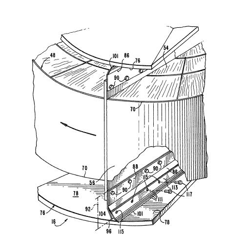
~; The housing includes a plurality of sector plates
76, each sector plate having a sealing surface 78 which faces
toward the drum 48. Sector plates 76 diYide the housing into
an air intake half 80 and a gas discharge half 82. The plane
84 representing the boundary between these two halves, 80, 82
is shown in Fig. 3. As is particularly apparent from Fig~ 3,
there is one pair of sec~or plates disposed adjacent the hot
end 72 of drum 48 in face-to-face relationship wi~h hot end
72 and another pair of sec~or plates 76 disposed adjacent the
cold end 74 of drum 48 in face-to-face relationship with cold
end 48. Each sector plate 76 corresponds in configuration to
a sector 58 of the drum.
In addition to the four sector plates specifically
referred to and shown herein, there may be additional sector
plates as wellc For instance~ there may be a pair of oppo-
sitel~ disposed ~ector pla~es a. the hot and cold ~nds which
are axially aligned with each other and which are disposed at
the air intake hal~ 80 of the air preheater to divide the air
intake half into on~ relatively small portion for primary air
and another relatively larger portion for secondary air.
Diaphragms 56 of drum 48 include a ~et of semi-
rigid radial seal plates coupled with diaphragm members 60 to
25 extend lengthwise along diaphr~gm members 60, specifically,
-- 12 --
` ~ ~
along their radial edges 61, 52 at the hot and cold ends 72,
7~ of drum 48. Radial seal plates 86 are rigidly attached
to diàphragm members 60 by holding members 8$ and secured by
~astene~s 90. As shown in Fig. 7, there may either be a sin-
gle radial seal plate 8~ extending generally radially out-
wardly from the edges 61, 62 of diaphragm member 60 (but at
a slight incline to diaphragm member 60~ or, as shown in Fig.
8, there may be a pair of radial seal plates 86 ex~ending
radially outwardly rom diaphragm member 60 at different
inclines with respect thereto.
Radial seal plates 86 are fixedly and ri~idly at-
tached to diaphragm member 60 by holding members 88 secured
by fasteners 90. Each radial seal plate 8~ has a width 92
(FigsO 6, 7 and 9~ extending normal to its length 94 (Fig.
5). Aside from their previously described radial extension
along the diaphragm members 60, the r.adial seal pla~es 86
al8o extend generally axially from the drum in the direction
of their widths~ each radial seal plate having an outer ra-
dially extending edge 96 most remote from ~he drum 48. ~s
already alluded to, reference to the radial seal plates 86
extending ~ax;ally~ from the diaphragm member 60 is not meant
to imply that th~ radial seal plates are necessarily in the
same or parallel plane as the directly radially extending dî-
aphragm members 60. Rather, "radially~ in this context sim-
ply mean~ that there is a sign~ficant radial component to the
- 13 -
direction of extension of the radial seal plates ~6. Tt will
be apparent from the drawings, particularly Figs. 7, 8, 9, 10
and 'l 1, that there is also a tangential component to the out-
ward ex~ention of the radial seal plates 86, inasmuch as the
seal plates 86 are inclined with respect to a plan~ which
would be coincident with or parallel to the directly radially
extending diaphragm member 60. The radial seal plates 86 are
of such rigidity so as not to normally yield during operation
of the air preheater 16 but so as to yield to a limited ex-
tent should the radial seal plates 86 and sector plates 76
happen to come into contact with each other during
operation.
During relative movemen~ between the drum and the
housing~ the outer radially extending edges 96 of the radi-
al seal plates 86 will normally pas ~ sely b =
That is, there is normally a small clearance 98 between the
outer radially ex~ending edqe 96 of radial seal plate B6 and
the sealing surface 78 of sector plate 76 (Fig. 6). While in
theory, the i~ea is to maintain a small ye~ definite clear-
ance ~8, in practice, this is not an easy ma~ter. At the hot
end of the drum 48, the parts of the air preheater 16 tend to
expand which, in turn, can redu~e the clearance to zero and
cause the seal plates 86 to clasn with sector plates 76
Since sector plates 76 are constructed of a generally stiff,
semi-ri~id metal plate material, this me~al-to-metal contact
- 14 -
can be quite disadvantageous and can lead to failuces. On
the okher hand, the opposite problem of too much clearance
is also frequently experienced in practice. Misalignments,
wear, tolerance stackups, and deformation of parts can cause
clearance 98 to be considerable at some points in the air
preheater, thus causing leakage between the air and gas
halve 80, 82 which, in turn, leads to inefficient oper
a~ion.
These problems are overcome through the use of a
set of foil~liXe metal radial sealing strips 101 coupled to !
radial seal plates 86 adjacent the outer, radially extending
edges 96 of seal plate~ 86. The radial sealing strips 101
extend along substantially the entire radial lengths 94 of
radial seal plates 86 and extend outwardly of seal plates 86
in at least a partially axial direction with respect to drum
48 when the radial sealing strips are not deformed by engage-
ment wi~h ~he sector plates (such condition being shown in
Figs~ 7 and 8). AS will be described in more detail herein-
after, the radial sealing s~rips 101 selectively and yield-
ingly engage the sector plates 76 (see Figs~ 9-11 ) to effect
sealing between the drum 48 and housin~ 46 of the air pre-
heater in operation.
I will be apparent that the radial sealing strips
101 are of a substantially thinner material than the radial
seal plates 86 and are substantially more flexible than the
- 15 -
.
. ~
radial seal plates 8~. The radial sealing strips 101
are constructed of a hard, corrosive-resistant, high-
alloy material. The specific radial sealing s-trip 101
just described has a -thickness of not more -than 0.005
inch, while the radia:L seal plates 86 to which they
are attached typically have thicknesses in the range
of 0.02 to 0.10 inch. Radial seal plates 86 are
approximately 5 to 25 times thicker than the ~oil-like
radial sealing s-trips 101.
Each radial sealing strip 101 includes a working
face or advancing side 103 for selectively enga~ng -the sector
plates 76 and a non-working face or trailing side 105 which faces
away from the working face 103. Radial sealing strips 101 also
include a rree distal edge or side edge 107 disposed remotely from
the associated radial seal plate 86 when the radial
sealing strip does not engage a sector plate 76 (i.e.,
when the sealing strips are in the conditions shown
in Figs. 7 and 8). Opposite free distal edge 107
is an inner side edge 109 adjacent to which radial
sealing strips 1.01 are coupled with their associated
radial seal plates 86.
To obtain the proper bending and flexing
characteristics for the radial sealing strips 101,
a plurality of backing strips or strip portions 111
partially overlie the non-working face 105 of each
radial sealing strip or base strip portion 101 to
form a stack of strips as shown in Figs. 7-11. Each
backing strip extends from inner side edge 109
-16-
.
'
,
~'7~
of the associated radial ~ealing strip 101 toward, but not
completely to, ~ree distal edge 107 of the radial sealing
stri~ It is possible, however, that only certai.n ~ucceeding
backing strips in the stack extend toward the free distal
edge 107 to a le~ser extent than the previous backing strip.
For instan~e, the steps" formed by the backing strips might
be formed by pairs of backing strips 111. Each succeeding
backing strip in the stack extends toward free distal edge
107 to a lesser exten~ than the previous backing strip so
that the strips are disposed in a staggered, step-like ar-
rangemen~. The backing strips are of comparable thickness
to the thin foil-like radial sealing strips 131, but may be
somewhat thicker. The preferred range of thickness for the
backin~ strips is 0.004 - 0.010 inch.
The ~taggered backing strips 111 affect the bending
characteristics of radial sealing strips 101 by increasing
their re~istance to yielding move~ent out of the plane of the
radial seal plates 86 to which they are attached. ~e~, at
the same timej the staggered backing strips 111 permit full
yielding movem~nt even to the extent where the radial sealing
strips 101 will move out from between the clearance 98 be-
tween radial seal plate 86 and sector plate 76 if the la~ter
tw-, parts happen to come into contact during operation, as
~hown in Fig. 11. That is, free distal edge 107 is movable
away from the inner side edge 109 when the seal body made up
- 17 -
~'7~
of strips 101 and 1 1 t engages sector pla~e 76 during opera-
tionr such that free distal edge 107 becomes a trailing edge.
The d;irection from the inner side edge 109 to the free dis~al
edge 107 is the trailing direction. The free distal edge is
completely unobstructed from yielding movement in a trailing
direction, iOe., it has as much freedom of movement in the
trailing direction as the flexure characteristics of the seal
body made up of strips 101, 1 1 1 permits.~
. The ability of the sealing strips 101 to flex to
this exten~ is important to prevent damage to the radial
sealing strips in a condition of minimal clearance or zero
clearance as shown in Fig~ 11. This notwithstandingt it is
important that the sealing strips 101 have a sufficient re-
sistance to yielding movement to prevent differential pres-
sure between the two halves ~0, 82 of air preheater 16 from
lifting radial sealing strips 101 ou of engagement with
sector plate 76 when the ra~ial seal ing strip 101 is wiping
along a sector plate 76 during movemen~ of the strip from the
relatively low pressure gas discharge half 82 toward the
20 rela.tiv~ly high pre~sure air intake half 8~. The ~lex char-
acteristics given to the radial sealing s~rips tOl by the use
of the staggered backing strip~ 111 meet these countervailing
re~uirements.
Adjacent the inner side edge 109 of the radial
sealing strip are mounts 113 for rigidly and fixedly mounting
- 18 -
~ 4)~
.he saal body ( the seal body bein9 ~om~eoSed o ~che radial
d in the particular e
111 ) on the radial seal p a
~ thrOu9h the radial seali 9
ide edges. Fas~eners 11
15 ~o couple each seal body
sealing strips) to its associated diaphr39nn 66 (and speci-
~i~ally ~co i~s a5sociated radial seal plate 86 couple~ tob 60 ) to extend alon9 on
10h agm member in such Ps
trip selecti~ely engage
during relative movemen~ between the preheater ~ortions to
1se hi lf 80 and gaS disCb 9
air preheater ~ith
15Figs. 7 and 8 depict radial sealing s~rip ~01 i~
its ~os~ relaxed condition, i7e- ~ a condition in whiCh the
trip ~3Oes no~ engage th
dial sealir~9 striP 101 is
in Fig. 9-11, each radial sealing st~il? 101 is freely~ elas
i t I secol~d elastically d
9age~ent ~ith ~h~ seal g
t effect seaiing between
h l~es or portions o the
amOunt of def~matin
25nount o deformation,
_ 19 ~
:
complete de~ormation, i.e., deforma~ion such that the radial
sealing strip 101 no longer e~tend~ axially outwardly of the
radial seal plate 86. Thi~ latter deformation being the re-
sult of radial seal plate 86 coming into contact with the
sector plate 76. Any one of the conditions of deformation
shown in FigsO 9-11 can be considered a maximum deformation
or ~most deformed" eondition, such condition depending simply
upon the particular clearances or lack thereof available in
any particular air preheater.
~ousing 46 of air preheater 16 includes a pair of
annular circumferential members 121 at both the hot and cold
ends 40, 42 of the air preheater and disposed adjacent the
hot and cold ends 72, 7~ of ~he drum 48. Annular circumfer-
ential members 121 each define an annular sealing surface 123
in the housing, annuiar surfaces 123 being disposed adjacent
to ~he circular edges 70 of the drumv Of course, one of ~he
annular surfaces 123 is disposed adjacent the hot end 72 of
the drum, and the other annular surface 123 is disposed ad-
jacent ~he cold end o drum 48~ Annular surface 123 has a
cylindrical shape, i.e., it is configured like an inwardly
facing surface defined by a cylindrical bore in the partic;
ular embodiment shown and described herein. Nevertheless,
~annular surfaceN as used herein is not intended to be lim-
ited to this type of cylindrical surface. Rather, the ~ermi-
nology is intended to encompass other ring-like suraces such
- 20 -
as, for instance, a ring-like surface disposed flat in a sin-
gl~ planer such as represented by surface 125 in Fig. 6.
~; Drum 4~ includes a set of semi-rigid circumferen-
tial seal plates 131 coupled wi~h both the hot and cold ends
72, 74 of drum 48 adjacent outer circular edges 70 thereof~
Each circumferential seal plate 131 includes an inner edge
135 adjacent to which the seal plates 131 are attached to the .
circular edge 70 of the drum and an outer circumferentially
extending edge 137, edge 137 being that edge which is most
remote from the drum~
Circumferential seal plates 131 are attached to the
outer circular edges 70 of drum 48 through the use of clamp-
ing devices, one form of which is repres~nted by reference
numeral 139 in Fig. 4, and another orm of which is represen-
ted by reference numeral 139' ;n Fig. 12. Clamping d~vices
1390 139' include a seal plate 141 (Fig. 4)9 141' (Fig. 9),
a set screw and lock nut 143 ( Fig . 4 ), 1 43 ' ( Fig . 9 ) and a
holding member 145 (Fig~ 4), 145l (Fig. 9). Circumferential
seal plates t31 may include indentation8 147 which allow the
:20 ~ plates to be easily deformed to assume a slightly ~rcuateconfiguration corresponding to the arc of the circular edges
70 of drum 4B. In the plaoe of inden ations 147, cut out
areas ~not shown) corresponding generally in size and con-
figuration to indentations 147 may serve the same purpose.
Sem~-rigid circumferential seal plates 131 are of such
- 21 -
- ' ' , . ~,
rigidity a~ to no~ normally yield during operation of the air
preheater but so as to yield to a limited extent should the
circumferential seal plates 131 and annular surface 123 of
the housing happen to come into contact with each o~her in
operationO
During relative movement between drum 48 and hous-
ing 46 (which in the specific embodiment shown and described
herein will be a rotary movement o the drum 48 with respect
~o the stationary housing 46) r outer circumferentially ex~
tending edge 137 of each circum~erential seal plate 131 will
normally pass closely by the annular sealing surface 123 of
the housing. That is, there is normally a small clearance
or gap 149 between the outer edge 137 of the circumferential
seal plate 131 and the annular sealing surEace 123 of the
housing (Fig. 6). As with radial seal plates 86, the idea
is to maintain a small yet definite clearance 149. As with
the radial seal plates 86 too, maintaining such a clearance
or gap 149 is no~ an easy matter in practice. Again, misa-
lignment, wear, tolerance stackups and deformation of parts
are quite common, which often makes gap 149 between the
~ircumferential seal plates and the annular sealing surface
123 variable from no gap at all, causing a metal-to-metal
clash, to a very wide gap, such as three-quarters of an inch~
causing substantial leakage between the air intake and gas
discharge halves 80, 82 of the air preheater 16.
- 2~ -
These problems are overcome through the use of a
set o flexible circumferential sealing strips 151, each com-
posed of a thin metal foilp speciflcally, a hard corrosion~
resistant, high-alloy foil4 Circumferential se~ling strips
15t are couplsd with the circumferential seal plates 131 ad-
jacent outer edges 137 of seal plates 131. Circumferential
sealing strips 151 extend along substantially the entire cir-
cumferential distances of circumferential seal plates 131.
The widths 152 (Fig. 2) of strips 151 extend in at least a
partially radial direction~ In this regard, it will be un-
derstood that Wradial~ means a substantial component of ra-
dial extension. As will be obvious from Fig. 12, there is
also a certain axial component to the extension of circumfer-
ential sealing strips 151 in view of the bends and inclines
thereof wi~h respect to edge 70 of the drum 48.
~ ircumerential sealing strips 151 include a basal
side edge 153 adjacent ~o which the strips 151 are mounted
with respect to the drumO Each strip 151 also includes a
distal side edge 1~5 opposite to and remote from basal side
edge 1~3. AS .will be apparent from Fig. 12, circumferen-
tial sealing strips 151 are attached to drum 48 adjacen~
itR circular edge 70 by the same clamping device 139' (with
support clip 141', set screw and loc~ nut 143' and holding
member 145') as is used for attaching circumferential seal
plates 131 to drum 48. In this regard, the areas of the
- 23 -
~26'~
circumferential sealing strips 151 adjacen-t thelr
basal slde edges 153 serve as -the mounts for circum-
ferential sealing strips 151 and cooperate with the
clamping device 139' to eEfect mounting. Of course,
circumferential sealing strips 151 will be disposed
on both sides of -the drum at the hot and cold ends
72, 74, to ride over -the stationary annular surface
125 as drum 48 rotates with respect thereto (in the
particular embodiment shown and described herein).
This, in turn, will effect sealing of the air preheater
by minimizing leakage around the outer periphery of `
the drum in a generally axial direction which leakage
would, of course, cause the air preheater to operate
inefficiently, and may include the inner perimeter.
The best circumferent.ial sealing is obtained
by providing a basal bend 157 in each circumferential
sealing strip 151 adjacent basal side edge 153. sasa
bend 157 matches a corresponding bend 158 in circum-
ferential seal plate 131. Bend 158 is disposed adjacent
20 inner edge 135 of seal plate 131 and adjacent the area
of connection of seal plates 131 to drum 48. Basal
bend 157 and corresponding bend 158 will typically
range between about 40 and 70 from a line 160 at the
circumference of -the drum and parallel to the axis 161
25 of the drum. Basal bend 157 biases circumferential
sealing strip 151 toward engagement with annular
surface 123 of the housing 46 oE the air preheater 16.
-24-
, :
.
Each clrcumferential sealing strip 151
also includes a clistal bend or sharp bend 159 adjacent
distal side edge 155 thereof. The distal bend 159
directs distal side edge 155 toward face-to-face
confronting engagement with one of the annular surfaces
123 of housing ~6 to e~fec-t circumferential sealing.
Preferably too, the por-tion 163 of the circumferen-tial
sealing strip 151 ex-tending between the distal bend
159 and the distal edge 155 will be generally trans-
verse to the surface 123. That is, the smallerangle 164 of the two angles formed by the intersection
of the plane of the portion 163 with the surface 123
will preferably be greater than 60, unless the angles
are approximately equal, i.e., approximately 90.
Distal bend 159 is a sharper bend than
basal bend 157. Preferably, distal bend 159 will
be between 60 and 90. As will be apparent from Fig.
12, the sharp or distal bend 159 is spaced from but
adjacent to dlstal side edge 155. On the other hand,
basal bend 157 is spaced from and remote from both
distal bend 159 and distal side edge 155.
As can best be seen from Fig. 15, distal side
edge 155 preferably does not actually engage surface
123. Rather, a flat wear bar 165 is affixed to the
circumferential sealing strip 151 ad]acent distal edge
155. Specifically, wear bar 165 overlies portion 163
of strip 151 and extends therealong in parallel,
contiguous relationship thereto for substantially
-25-
~ , . . . ~ :
.
. . , ~ ' " ' ~ .
7~
the entire length of strip 151. The largest surfaces of wear
bar 165 approximately correspond in their si2e and shape to
portion 1~3 of circumferential seal strip 151~
It will be seen that the small distal side 167
of wear bar 165, i.e~, the side which corresponds generally
with distal side edge 155~ extends slightly beyond distal
side edge 1550 Thus, small distal side 167 of wear bar 165
rather than distal side edge 155 of the circumferential seal-
ing strip 151 actually engages the sealin~ surface 123 in con-
fronting, ~ace-to-face relationshipO Because wear bar 165 is
substantially thicker than the metal foil of circumferential
sealing strip 151 and presen~s a larger surface area (i.e~,
that of side 167) to sealing surface 123, it will not cut into
sealing surface 123 and will provide longer wear than would be
so if the distal edge 155 of the sealing strip 151 were to en-
gage the sealing surface 123 directly.
It will be apparent that the specific features and
arrangements of the circum erential seal plate t31 as des-
cribed herein and shown in the drawings permit each sealing
~ : strip to yieldably ride over the annular sealing surface 1~3
o~ housing 46 when the drum 48 is moving relative to housing
46. In this regard, the circumferential sealing strips 151
can be considered seal bodies which ensnge the annular seal-
ing surace 123 and which move in response to irregularities
- 26 -
in the sealing surface and irregularities between the drum
and housing to effect ~sealing therebetween.
As with the radial sealing strips 101, circumfer-
ential sealing strips 151 are freely elastically movable
5 between a first, most relaxed condition and a second, most
elastically deformed condition in response to engagement with
a sealing surface of the air preheater to effect sealing
between the movable and stationary portions of the air pre-
heater. As with the radial sealing stripst the most relaxed
condition and most elastically deformed condition will depend
upon the peculiarities of each individual air preheaterO Of
course, in an air preheater having unusually severe discrep-
ancies in the amount of clearance between the circumferential
seal plates 131 and annular surface 123, the first, most re-
laxed condition and second, most elastically deformed condi-
tion will also be extreme.
Fig. 12 shows a typical or average condition of
flex bias for ~ealing strip 151. In Fig. 12, there is a
clearance between the outer edge 137 of the circumferential
seal plate 13t, but not an unduly large clearance. In Fig.
13, on the other hand, there is illustrated a very large
clearance and a rather extreme condition of movement of strip
151 toward its relaxed condition to accommodate the large gap
between the circumferential seal plate 131 and annular seal-
ing surface 123. Fig. 14 illustrates a lack of clearance and
1;2~; d ~
a severe condition of bias in a direction toward the most de-
formed condition of sealing strip 151. The condition shown
in Fi~. 13 may be considered a "most relaxed" condition for a
. particular installation although, as already explained, the
most relaxed condition will not always be as illustrated in
Fig. 13, particularly not in those applications where the
clearances remain small. Likewise, Fig. 14 can be consid-
ered a "most deformed" condition, although in certain air
preheaters the extent of deformation of sealing strip 151
will not be as severe, particularly not where a clearance
always remains between the circumferential seal plates and
the annular surface 123~ -
It will be apparent that sealing strip 151 is in aconstant condition of bias when it is`fixed, adjacent its in-
ner edge 135, with respect to circular edge 70 of the drum of
air preheater 16 and when the small distal side 167 of wear
bar 165 is thus biased into engagement with annular sealing
surface 123 of the housing portion 46 of the air preheater.
It will be appreciated that the most relaxed condition of
the circumferen~ial sealing strip is that condition wherethe sealing strip has moved in the direction of bias to its
greatest extent toward a fully relaxed condition to accommo-
date a maximum clearance between the circular edge of the
drum ~as specifically embodied by the outwardly extending
seal plates 131 thereof) and the adjacent annular surface
28 -
.
125. It wlll also be unders-tood that the most
elastically deformed condition is that cond:ition where
the sealing strip 151 has moved to the greatest extent
counter to the direc-tion of bias to accommodate a mini-
mum clearance between the circular edge of the drum~as embod.ied hy outer edge 137 of circumferential seal
plate 131 of the drum 4~) and adjacent annular surface
123 of the housing.
The circumferential sealing strips 151 are of
roughly comparable ~hickness -to the thin, foil-like
radial sealing strips 101, but the circumferen-tial strips
will preferably be somewhat thicker. The preferred range :~
of thicknesses for the circumferential sealing strips 151
is 0.010 - 0.020 inch. The circumferential seal plates
15 131 to which circumferential sealing strips 151 are
attached have a thickness and rigidity comparable to
that of previously described radial seal plates 86.
That is, the circumferential seal plates 131 will
typically have thicknesses in the range of 0.06 to
: 20 0.10 inch. i'ile circurnferential seal plates 131 are
approximately 2 to 25 times thicker than the ~oil-like
circumferential sealing strips 151.
Lt will be seen that the metal foils or both
the radial and circumferential sealing strips are free of
any surrounding material, with the exception of the wear
bar on the circumferencial sealing strips. Even where
backin~ strip portions are used in connection with the
radial sealing strips, these backing portions are them-
-29-
,' ' ' ' : '
'
:
selves me-tal :~oils.
With the arrangment as described herein and
shown in the drawlngs, it will be apparen-t that
provision has been made ~ -
-29a-
. . ,' ~ ' ':
., ' ' .
'4~
for sealing an air preheater to minirnize leaks both between the
intake air and gas discharge sides oE the preheater as well as
minimi~ing leaks around the periphery of the drum which contains
a maxtrix of heat exchanging elements. It will also be seen that
S this is accomplished through a sealing arrangement which accommo-
dates for large variations in the clearances, or lack thereof,
between the relatively moving parts of the air preheater and ir-
regularities in such parts~ such variations and irregularities
being commonly experienced in pra~tice. It will also be seen
that the circumferential sealing arrangement of the present in-
vention eliminates any need ~or an axial sealing arrangement as
well. Further, it will be seen that this is accomplished through
a simple and economical sealing arrangement which can be instal-
led in commercially available air preheaters without major modi-
fication thereto.
Terms such as right and left, upper and lower, aboveand below, and other relative terms have been used herein. It
will be understood that these terms have been used to describe
relative relationships only and are not to be construed as lim-
iting. For instance, what is "above" or to the "right" from oneframe of reference may be "below" or to the "left" from another
frame of reference.
Also, the invention has been described by way of a pre-
ferred embodiment thereof, and it will be understood that many
variations and modifications are possible. Thus, the invention
is not limite~ by the foregoing description, but rather encompas-
ses many embodiments and variations within the scope of the ap-
pended claims.
- 30 -