Note: Descriptions are shown in the official language in which they were submitted.
5S~:j
BACKG~OUND AND SUMMARY OF THE INVENTION
This invention relates in general to holders for
cut photographic film. More specifically, it is directed
to a new disposable package for cut photographic film, and
an improved holder for use therewith.
In the field of professional photography, the use
of relatively large format cut photographic film is
preferred for many applications. This type of film is
conventionally preloaded in the dark room into rectangular
film "holders," each of which accommodates two sheets of
cut film. Such film holders are subsequently inserted
into an aperture in the back of the camera for exposure,
withdrawn and returned to the dark room for unloading and
developing. An example of this type of holder is sold by
Lisco Manufacturing Co. under the trade name "LISCO REGALn.
In order to have an adequate supply of film, it is
necessary for the photographer to preload a large number
of such film holders, to transport them to the location
where they are being used, and to transport them back to
the dark room for unloading and processing. Such an ~
arrangement has a number of disadvantages. Primary among
these are the relative bulk and weight of the holders
themselves, each loaded holder weighing about 7 ounces, the
time required to preload the holders, the potential ~or
incorrect loading, and the risk of contamination and finger
prints. Temperature and oxidation control of the unused
portion of the film stock contained in the opened bulk pack
in which the supply of cut film is purchased are also a
problem. Once the air tight manufactuer's seal is broken to
*Trade Mark
., ,: . ...
': , . .: . . .,~, . .:
.
` ` ., ~ - '''
,
: : : . : ,
~`~
55S
- 2 ?
remove only a few sheets of color film from a bulk pack, the
remainder cannot be returned to cold storage, as is generally
required with professional photographic film, because of
moisture condensation risk; and because the package is no
longer airtight, the film begins to oxidize. Thus, if the film
in a broken pack is not used promptly, it is usually discarded
to avoid the risk of spoilage and loss of work product.
A number o~ attempts- have been made in the past t~
remedy these problems by providing a disposable film package
which can be loaded into a film holder in daylight at the point
of use, and withdrawn after the film has been exposed. In this
manner, a single holder can be reused, eliminating both the
need to transport large numbers of film holders on location,
and the requirement for dark room preloading and unloading o
film by the photographer.
Typically such disposable film packages consist of a
substantiallv flat film carrier to which two sheets of cut film
are attached, one on each side of the carrier. The carrier is
?ackaged in an envelope having one open end through which the
carrier may be withdrawn fqr exposure. ~n use, the film
?ackage is to be inserted into the holder, open end first so
tha. the sheets of fil.m are properly positioned in the holder
for exposure in a camera. Once the packase is fullv inserted
into the holoer, means are provided for locking the carrier in
posi-ion so tha~ the envelope may be withdrawn leaving the
sheets of film ready to be exposed. After exposure, the
envelope is to be reinserted into the holder, over the film
carrier. The cacrier is then unlocked so that the package,
with the carrler once again contained in the envelope, may be
removec, turned over and reinserted to expose the second sheet
Of fil~.
555
-- 3
Two examples of such disposable film packages are
disclosed in ~.S. Patent Nos. 689,271 to Ashford et al. and
1,505,000 to Whiting. One of the principal difficulties
encounterea in all such prior art film packages centers around
the necessity of providing and maintaining a light tight seal
at the open end of the envelope at all times when the package
is outside of the holder. The Ashford et al. patent attempts
to provide such a seal by means of an enlargement at one end of
the carrier having a recess .into which the edges of the open
end of the envelope may be inserted. The principal
disadvantage of the Ashford et al arrangement is that the
light tight seal is particuarly apt to be breached by
incomplete or incorrect reinsertion of the envelope after its
withdrawal for exposure of the film, by improper seating of the
L5 open end of the envelope due to incorrect alignment with the
recess upon reinsertion, or by separation of the open end of
the envelope from the recess due to jostling upon withdrawal.
This difficulty is compounded by the fact that both the Ashford
et al. and Whiting inventions anticipate that the envelope will
~0 be completely withdrawn from the carrier, thereby causing a
. certain amount of jiggling of the carrier as the operator
attempts to align the envelope for reinsertion.
This shortcoming was less important at the time when
the Ashford et al. and Whiting packages were conceived because
'5 the relatively slow speed of film then in use allowed the
photographer adequate opportunity to correct any break in the
light seal due to incorrect or improper seating of the
envelope. With modern high speed photographic film, however,
any light leakage, however small, is likely to ruin a piece of
film in only a tiny fraction of a second.
-, .. .
~ 2 ~S ~S
AccordinglY, it is a principal object of the present
invention to provide a disposable film package having a highly
dependable means for establishing and maintaining a light tight
seal at the open end of the packagels outer envelope.
5Another object of this invention is to provide a
disposa~le film package which may be withdrawn from the film
holder in such a manner as to prevent accidental breach of the
light tight se21~ . _
Another object of this invention is to provide a
10disposable film package with means to assure withdrawal of the
external envelope only as far as is necessary to allow complete
exposure of the film.
Still another object of this invention is to provide a
disposable film package having means to provide for the correct
15alignment of the envelope and the carrier upon reinsertion of
the envelope into the holder, thereby assuring correct and
complete sealing of the open end of the envelope.
Yet another object of this invention is to provide a
new film holder for use with the disposable film package, which
20is simple, lightweight, e,conomical in construction and
convenient to use.
Another object of this invention is to provide a new
film holder for use with the disposable fiim p2ckase having
improved means for retaining the carrier in the holder when the
25film is withdrawn.
These and other objects of the invention will be more
fully understood from the following detailed description of the
preferred embodiments which should be read in lisht of the
accompanying drawings.
i .'5~j~
BRIEF DESCRIPTION OF THE DRAWINGS
Fig. 1 is a plan view of a film carrier which forms a
part of the disposable film package in accordance with the
teachings of the invention.
Fig. 2 is a longitudinal sectional view taken
generally along line 2-2 of Fig. 1.
Fig. 3 is an enlarged detail view of a portion of Fig.
2.
Fig. 4 is a perspective view of the disposable film
package with the carrier partially withdrawn therefrom.
Fig. 5 is a plan view of the disposable film package
with the carrier fully inserted therein.
Fig. 6 is a longitudinal sectional view taken
generally along line 6-6 of Fig. 5.
~ig. 7 is a plan view showing the inside surface of
the cutout from which the envelope of the disposable film
package is formed.
Fig. 8 is a plan view showing the exterior surface of
the cutout.
Fig. 9 is a plan view of the enclosure base, which
~o . fo.ms a part of the film holder in accordance with the
teachings of the invention.
Fig. 10 is a side view of the enclosure base of Fis. 9.
Fig. 11 is an end view of the enclosure base of Fig. 9.
Fig. 12 is a transverse sectional view taken generally
'5 along line 12-12 of Fig. 9.
Fig. 13 is a lonsitudinal sectional view taken
generally along line 13-13 of Fig. 9.
Pig. 14 is a plan view of the enclosure cover, which
forms a part of the film holder in accordance with the teaching
o of the invention.
5~5
- 6
Fig. 15 is a side view of the enclosure cover of Fig.
14.
Fig. 16 is an end view of the enclosure cover of Fig
14.
S Fig. 17 is a longitudinal sectional view taken
generally along line 17-17 of Fig. 14.
Fig. 18 is an enlarged detail view of a portion of
Fig. 17.
Fig. 19 is a plan view of a film holder in accordance
with the invention.
Fig. 2Q is 2 longitudinal sectional view taken
aenerally along line 20-20 of Fig. 19 showing the enclosure
cover and enclosure base in their open or retracted position.
Fig. 21 is a longitudinal sectional view taken
generally along line 20-20 of Fig. 19 showing the enclosure
cover and enclosure base in their closed, camera set position.
Fig. 22 is an end view of the film holder of Fig. 19,
showing the enclosure cover and enclosure base in their open or
retracted position.
Fig. 23 is an end viçw of the film holder of Fig. 19,
showing the enclosure cover and enclosure base in their closed,
camera set position.
DETAILED DESCRIPTION OF T~iE PREFERRrD EMBODIME~S
Referring now more particularly to the drawings, and
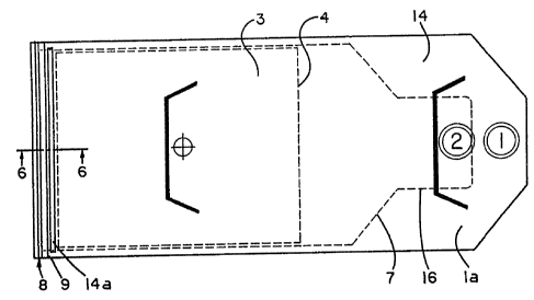
s?ecifically ~o Figs. 1-3, there is illustrated a photographlc
'5 film carrier, generally designated 1, to which may be
detachably secured two sheets of cut photographic film 2 in a
film carryins resion 3 on either side of the carrier. ~ach of
the film sheets is held in place on the carrier by an adhesive
backed opaque ?eripher?1 ~ask 4 having a non adhesive backed
5~
tab 5 which may be grasped to facilitate removal of the film
from the carrier for processing.
At one end of the carrier there is an elongated tab
portion designated generally as 6. In the preferred
5 embodiment, the width of the tab is substantially smaller than
that of the film carrying region 3, and the width of carrier
increases gradually from the elongated tab 6 to the film
carrying region, so that the edges of the carrier are inclined
as shown at 7. - ~
At the other end of the carrier 1 is a rigid light
sezling clip 8 which extends transversely of said carrier,
ex'ending somewhat beyond the edges thereof as shown at 9. In
the preferred embodiment, the carrter and the light sealing
clip are made of ~olded and stamped opaque plastic. The clip 8
15 has a first pair of transverse flanges lO which are inclined
relative to the plane of the carrier, toward the tabbed end
thereof, and a second pair of transverse flanges 11 disposed in
parallel spaced relationship to the plane of the czrrier
thereby defining a pair of transverse recesses 12 between the
20 clip and the carrier. The edges 13 of the second pair of
transverse flanges 11 are inclihed relative to said carrier,
towzrd the tabbed end thereof so as to provide said clip 8 a
funnel shaped cross section as best seen in Fig. 3.
The carrier 1, with the film 2 and mask 4 attached
25 thereto are packaged in an opaque light excluding exterior
envelope i4 having one open end 15, as shown in figures 4-8.
Figure 4 depicts the film package designated generally as la
with the carrier 1 partially withdrawn from the open end 1; of
the envelope 14. Figs. 5 and 6 show a plan view and a partial
30sectional view (6-6), respectively of the envelope 14 with the
carrier fully inserted therein. As can best be seen in Fig. 6,
5~5
-- 8 --
when the carrier is fully inserted into the envelope, the
edges 16 of the open end 15 of the envelope engage with the
recess 12 of clip 8 to form a light tight seal.
As can also be seen in Fig. 6, envelope 14 has a
pair of raised portions or ribs 14a disposed transversely on
the exterior surfaces thereof. Said ribs, which may be
constructed of heavy paper or cardboard, cooperate with the
film holder in a manner to be described, to prevent the
withdrawal of the envelope farther than is necessary for the
complete exposure of the film.
As shown in Figs. 7 and 8, the envelope 14 is
constructed of a single die-cut sheet 17 of thin opaque
material such as plastic or paper. Figure 7 depicts the
interior surface of the cutout 17, while Fig. 8 depicts the
exterior surface thereof. To form the envelope, the cutout
is folded along line 18 and glued along edges 19 and at the
closed end 20. The glue pattern indicated by the cross
hatched area 21 in Figure 7 conforms to the shape of the
tabbed end 6 of the carrier 1, thereby forming an interior
pocket 22 of substantially the same size and shape as the
tab 6. A light trap made up of two strips of black velvet
23 is provided across the open end 15 of the envelope 14.
The external surface of the cut out 17 has printed
thereon alignment registration marks 25 and 25a, which
cooperate with the external contour of the film holder, such
as for example the existing Polaroid* Model 545 holder, in a
manner to be described, to prevent excessive withdrawal of
the film package therefrom.
As illustrated in Figures 9-23, the improved film
holder for use with the disposable film package is comprised
generally of an enclosure base 26 and an enclosure cover 33a,
the two being telescopically associated.
*Trade Mark
.,
..
~:
'' : ' ~" ' '
-.,: :'
-~
~ ~7~
_ g
As depicted in Figs. 9-13 the enclosure base 26
provides a raised, generally rectangular and planar film
supporting surface 27 having one transverse end portion thereof
29 depressed slightly from the plane of the film supporting
surface, as shown in Figs. 10 and 13. Also disposed
transversely of said film supporting surface is a strip of
black velvet 34. The film supporting surface is reinforced by
ribs 33 to strengthen it. Surrounding the film supporting
surface 27 is a channel 28. The exterior sides of the
enclosure cover 26 are defined by side walls 30, 30a and end
walls 31, 31a. Disposed along the interior surface of side
walls 30, 30a and end walls 31, 31a are a plurality of raised
tabs 32.
The enclosure cover 33a, shown in Figs 14-18, has a
generally flat upper surface 38 with a light transmitting
window 35 therethrough, as best shown in figure 14; two end
walls 37, 39 and two side walls 40, 41. End wall 39 has a
transverse slot 42 adapted to accept insertion of the
disposable film pac~age. The interior of upper surface 38 has
a transverse strip of black velvet 36, which cooperates with
velvet strip 34 on the enclosure base 26, to form a light trap
when the enclosure cover and base are nested as described
below. Projecting downward from the interior of upper surface
38 are three tabs 43. As is best shown in Fig. 18, the edge of
said tabs which is nearest slot 42 is inclined at an acute
angle with respect to upper surface 38, while the edge farthest
from slot 42 is inclined at a substantially perpendicular
obtuse angle to said upper surface.
The exterior transverse and longitudinal dimensions of
the enclosure cover 33a, as measured between the exterior
surfaces of side walls 40, 41 and end walls 37, 39, are
nominally smaller than the interior dimensions of the enclosure
,.:
tj755'j
-- 10 --
base 26, measured between the interior surfaces of side walls
30, 30a and end walls 31, 31a so that the two may be nested
together as shown in Figs. 19-23 to form film holder 47. When
enclosure cover 33a is inserted into enclosure base 26, as
shown in Fig. 20, tabs 32 on the interior of enclosure base
side walls 30, 30a and end walls 31, 31a engage with a
plurality of corresponding apertures 44 in enclosure cover side
walls 40, 41 and end walls 37, 39, to limit the extent of
outward movement of enclGsure cover 33a with respect to
enclosure base 26. As shown in Figs. 20 and 21, enclosure
cover 33a is biased by wave springs 45 into its outermost
(~open~) position with respect to enclosure base 26, as limited
by tabs 32 and apertures 44. When, however, downward pressure
is applied to the exterior surface of enclosure cover 33a, so
as to compress wave springs 45, said cover 33A moves to a
second, relative closer (~closed") position with respect to
base 26.
As can best be seen in Figure 20, the interior of
upper surface 38 of enclosure cover 33a cooperates with the
film supporting surface 27 of enclosure base 26 to form an
enclosed pathway 46 which communicates with the exterior of the
holder 47 through slot 42 in end wall 39 of the enclosure cover.
In use, the disposable film paclcage la is inserted
throush slot 42 along pathway 46 into position with the film
bearing region of carrier 3 disposed in aligned registration
with window 35 in the enclosure cover, and transverse light
sealing clip 8 residing in transverse depression 29 in film
supporting surfzce 27. Fig. 20 shows the holder 47 in the open
position with disposable film package la inserted therein. ~he
enclosure cover and base are then compressed into their closed
position as shown in Fig. 21.
75S5
- 11
Compression of the film holder 47 into its closed
position accomplishes three objectives. First, film supporting
surface 27 engages with envelope 14 and carrier 1, pressing
them against the interior of upper surface 38 of the enclosure
cover, thereby holding the carrier in a planar position
adjacent said upper surface and window 35. Second, velvet
strips 34 and 36 engage with the exterior of the disposable
film package la, to form a light t~ap, excluding ambient light
from pathway 46. Finally, tab i3 on the interior of upper
surface 38 of the enclosure cover moves downward into the
pathway 46 and engages with the edge of flange 11 on light
sealing clip 8 preventing the withdrawal of carrier 1 from
holder 47.
The thickness of film holder 47 in its closed position
is such that it may be inserted into a standard large format
camera in the usual manner, the spring loaded inte~ior surfa~es
of the camera back maintaining the film holder in its closed
position. With the holder in the camera, envelope 14 may be
withdrawn from carrier 1, by grasping the envelope in the
vicinity of glue pattern 21, sufficiently far to uncover film
adjacent window 35. Withdrawal of carrier 1 together with
~; envelope 14 is prevented by tab 43 which obstructs pathway 46
and prevents light sealing clip 8 from moving with said
envelope. The outward movement of the envelope is limited by
:
trdnsverse rib 14a on the outer~ surface of envelope 14, which
engages with stop 43a on the interior of the upper surface 38
of enclosure cover 33a when envelope 14 has been withdrawri a
suff~icient distance to be clear of window 35. Should ~top 43a
for any reason fall to engage rib .14a, the alignment
resistration marks 25 on envelope 14 provide the photographer
; with visual confirmation that the envelope has been fully
withdrawn, when the same are visible just clear of the film
holder.
1~75~5
After the film has been exposed, envelope 14 is
reinserted into the film holder 47 and over carrier 1 so that
the edges 16 of open end 15 of the envelope once again engage
with recess 12 in light excluding clip 8. Two features of the
disposable film package combine to assure that edges 16 are
properly seated in recess 12: First, tab 6 of carrier
cooperates with the shape of interior pocket 22 of envelope 14
as the latter is slid back into engagement therewith, to assure
that the envelope is properly aligned with the carrier and with
transverse light sealing clip 8. Second, the funnel shaped
cross section of clip 8 formed by inclined edges 13 serves to
guide the envelope into recess 12. Registration marks 25a
aford visual confirmation that the envelope has been fully and
properly inserted onto the carrier when said marks reside
immediately adjacent to slot 42 of the holder.
The film holder 47 is then withdrawn from the camera.
~ith the removal of pressure exerted by the camera back, wave
springs 45 will return the holder to its open position, with
tabs 43 withdrawn from engagement with light sealing clip 8.
At this point the disposable film package la may be withdrawn
from the holder 47. Since the carrler has sheets of film on
both sides, the package ~ay be turned over, reinserted into the
film holder and the process repeated.
It is most important that when the disposable film
package la is removed from the holder, the proper seating of
edges 16 of envelope 15 in recess 12 not be disturbed
Otherwise, tne light seal proviàed by clip 8 may be broken, and
fogsing of the film will result. Such occur ence is prevented
bv the protrusion of tab 6 (inside envelope 14), outside tne
holder when film package la is in the fully inserted position,
a distance which is sufficient to allow the photographer to
. .
.
12~i~55S
-- 13 --
grasp the envelope 14 in the area of tab 6 and to apply
pressure thereto, providing positive physical, and tactile
assurance that carrier 1 is withdrawn from the holder along
with envelope 14 and that the light tight seal provided by clip
8 is maintained.
It can be seen from the foregoing that the present
invention provides a disposable film package and film holder
which fully accomplish their intended objectives, and, due to
their simplicty, are well adapted to satisfy the practical
requirements of modern manufacturing processes.
Although the present invention has been described in
detail by way of illustration and example for purposes of
clarity, it should be understood that certain changes and
modifications may be made within the spirit of the invention.