Note: Descriptions are shown in the official language in which they were submitted.
~.2t~7~
FLEXIBLE PACKAGING APPARATUS AND METHO~
BACKGROUND AND STATEMENT OF THE INVENTION
This invention relates generally to methods and
apparatus for producing flexible packaging. More
particularly, this invention relates to methods and
apparatus for the continuous production of flexible
packaging wherein each individual package contains
a vacuum sealed controlled quantity of a non-solid
substance. Representative of such substances are
ointments and salves, for example.
It is the nature of flexikle packaging of the
type contemplated herein that two webs are joined
together and prior to the. joining, a vacuum is
applied so as to provide the desired sealed evac-
uated flexible package as the resulting or ultimate
product. In providing such packaging in the past,
it has been appropriate to join together the webs
in a horizontal relationship along a production
line and to continuously form across the breadth of
the webs being joined together a plurality of
packages simultaneously. In doing so, a manifold
applies to the webs a vacuum immediately prior to
the two webs being sealed and the individual
packages cut from the joined webs. Such procedures
provide a desirable package with an appropriate
quantity of the material contained therein under
the proper sealed evacuated conditions. However,
such procedures are cumbersome and time consuming
in this day of producing multiple quantities of
flexible packaging for various applications.
12~7~C~
( ~ )
It is important that a precise controlled
quantity of material be contained in each indi-
vidual package if, for example, the ointment or
salve is a medication requiring a precise con-
trolled quantity for later medical application to apatient. SUCh applications include, for example,
transdermal medication in which a flexible package
includes a special membrane with an adhesive
surface which may be applied to the skin of a
patient for a controlled administration of a
medication over a period of time. Such flexible
packages include a peel-off film over the adhe-
sively surfaced membrane which the user peels off
immediately prior to applying the package to his
skin.
As will be appreciated, such packages must have
a precise controlled quantity of an ointment
containing the medication so as to provide the
proper amount of medication over a period of time.
Supplying and joining the webs appropriate for
producing such packaging together in a horizontal
flat orientation and going through this sequential
application of vacuum, insertion of the material
involved, and the sealing of the various packages
together is a somewhat cumbersome process requiring
a rather slow output or production of such flexible
packages.
By contrast, with the invention herein, methods
and apparatus are provided for the continuous and
rapid production of a plurality of such flexible
; packages containing a non-solid material by joining
the two webs together in the nip of sealing rolls.
That is, a plurality of such packages are formed
simultaneously across the width of the webs being
~L~ti7~0~
-~ (3)
joined together in the roller nip which cooperate
to provide automatically and simultaneously the
formation, evacuation and sealing of each indi-
vidual flexible package in the webs. By utilizing
a joining together in the nip of cooperating rolls,
a much larger quantity of flexible packages may be
produced on a continuous basis in a much ~ore
simplified manner. The invention contemplates the
use of cooperating sealing rollers in which one
roll includes pockets for forming the individual
flexible packages cooperating with a second roll
which provides a proper pressure at the nip o~ the
rolls in order to form ~he individual packages
across the width o~ the webs being joined.
It has been found that by the use of the
specific kind of cooperating rollers, in accordance
with this invention, that no special vacuum appli-
cation need be made and that the flexible packages
are formed automatically and continuously in the
cooperating roller nip. In doing so, individual
quantities of the medication, salve or ointment to
be incorporated into the packages is applied to one
web immediately prior to the cooperating roller
nip. Thereafter, the individual quantities on the
web pass into the roller nip and are incorporated
into the individual packages. The individual
quantities o~ medication move into the related
pockets on the opposed roller at the cooperating
nip so as to provide automatically between the webs
being joined an individual evacuated pocket con-
taining the ointment or material to be contained in
the packages. As the individual pockets pass into
the nip, the two webs are joined together and
sealed automatically around the rim of the pockets,
as will be discussed in more detail below.
~2~
(4)
It will be understood by practi-
tioners-in-the-art, that the webs contain thermo-
plastic resin materials which may be joined and
sealed under the application of heat and pressure.
The crimp rolls which cooperate to provide the
sealed packaging on a continuous basis are heated
in order to provide the appropriate sealing of the
two webs together during the simultaneous forming,
evacuation and sealing of the flexible packages.
Once the two webs are joined together, the webs are
slit longitudinally into a plurality of strips each
containing therealong in spaced fashion a plurality
of formed and sealed flexible packages. Subsequent
to the slitting of the individual elongated strips
from the originally joined webs, the web strips
pass through a knife station which cuts the indi-
vidual packages from their elongated web strip for
collection and inspection.
Before describing this invention in more
detail, it may be well to note that the flexible
packaging procedures involved herein apply to a
variety of different materials which may be pack-
aged, as long as they contain a liquid component.
That is, ointments, salves and even oils may be
contained within the flexible packaging herein, as
long as the material involved will, when dropped on
the web and prior to being sealed in the roller
nips, hold a momentary self-contained body until
such time as the material is properly joined in the
evacuated flexible packaging formed by the methods
and apparatus herein. It will be understood,
furthermore, that a variety of different film
materials comprised of thermoplastics may be
utilized in the processing of the invention herein
~2~760~
( s )
for forming the webs which are joined together to
produce the flexible packaging. For example,
polyvinyl chloride, polyvinylidene chloride, poly-
esters, polyethylene and polyprcpylene are all
materials which may be utilized.
With the foregoing and additiona:L objects in
view, this invention will now be described in more
detail, and other objects and advantages thereof
will be apparent from the ~ollowing description,
the accompanying drawings, and the appended claims.
As purely illustrative of apparatus which may
be used for carrying out the process of this
invention, one may note the attached drawings in
which a schematic illustration of apparatus for
carrying out the invention is shown together with a
representative example of one of the crimp rolls
which cooperate to produce the flexible packaging
of the invention. Also, a representative package
which may be formed in accordance with this inven-
tion is shown and described.
DESCRIPTION OF THE DRAWINGS
Fig. 1 is a schematic illustration of apparatusfor carrying out this invention
Fig. 2 is a longitudinal elevational view of
one crimp roll for forming the flexible packages of
the invention, and illustrating the plurality of
pockets in the surface thereof for forming the
individual packages;
Fig. 3 is a sectional view taken along lines
3-3 of Fig. 2;
Fig. 4 is a sectional view taken along lines
4-4 of Fig. 2;
~2~7~
(6)
Fig. 5 is a sectional view taken along lines
5-5 of Fig. 2;
Fig. 6 is a plan view of one form of flexible
package produced in accordance with the methods and
apparatus of the invention; and
Fig. 7 is an enlarged sectional view of the
package illustrated in Fig. 6 and showing the
individual layers of material utilized to form the
package.
DETAILED DESCRIPTION OF THE INVENTION
Referring to the drawings in which like refer-
ence characters refer to like parts throughout the
several views thereof a roller type apparatus or
producing on a continuous basis, evacuated flexible
packaging containing materials with a li~uid
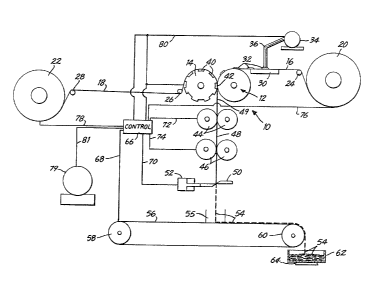
component therein is shown generally at 10. Thus,
cooperating crimp rolls 12, 14 form from webs 16,
18, a joined web 49 at cooperating nip 42. The web
16 is taken from a supply roll 20 with web 16
passing over a guide roll 24 prior to passing
through station 30 where quantities 32 of an
ointment, for example, to be incorporated into the
plurality of packages is deposited on web 16 from
an ointment supply 34 which passes through tubes 36
for the deposit of the material 32 on web 16.
~lthough not shown, it will be understood that a
plurality of material deposits 32 are deposited
simultaneously across the width of web 16. There-
after, the deposited materials 32 pass to the
cooperating nip 42 between rolls 12, 14 wherein the
material passes into cooperating spaces 40 on roll
14. The periphery of the pockets or spaces 40 on
o
(7J
roll 14 serves as the border for the sealing of the
material 32 between the webs 16, 18, as will be
discussed in more detail below,
Web 18 is drawn from a supply roll 22 and
passes over guide rolls 28, 26 prior to passing
around the cooperating crimp roll 14. After
passing through nip 42, the joined together web 49
containing a plurality of irlcorporated flexible
evacuated sealed packages in accordance with this
invention, passes to a pair of cooperating slitter
rolls 44. The slitter rolls slit the web 49 into a
plurality of longitudinal strips containing on a
continuous spaced basis a plurality of,the flexible
packages produced in accordance with this invention.
Once the web passes through slitter rolls 44
for slitting the web across the transverse extent
thereof, the web becomes a plurality of slit
longitudinal webs 48 which pass through friction
rolls 46 which serve to hold the slit webs 48 in
proper alignment for feeding the webs to the knife
station 50 wherein the individual longitudinal
slits of the web are cut into individual packages
54 which drop into a guide station 55 on the top of
conveyor 56. The belt of conveyor 56 passes over
spaced apart rolls 58, 60 in a conventional man-
ner. The conveyor 56 conveys the individual
packages 54 to a receiving container 62 at station
64 wherein filled c~ntainers 62 are removed so that
the individual packages may be inspected.
The knife station 50 operates under the action
of a reversible cylinder 52 under control 66
through line 70. As will be appreciated by prac-
titioners-in-the-art, all of the rolls in the
apparatus described are driven by motor 79 through
~7
(8)
conventional belts and reduction gearing in order
to provide the proper sequential operation and
rotational speeds of the various ro:Lls for con-
trolling the web passing through the apparatus.
Moreover, control 66 controls through line 80 the
dispensing container 34 and the quantity of mate-
rials passing through the lines 36 to make the
appropriate quantities and timing of ~he materials
32 on the top of web 16.
10As will be understood by practition-
ers-in-the-art, control 65 also controls through
lines 76, 78, the required braking necessary for
supply rolls 20, 22 respectively so that the webs
16, 18 are held in proper alignment for feeding to
15the cooperating crimp rolls 12, 14. Control 66, in
turn, through lines 72, 74 controls the proper
rotational speeds of the slitter rolls 44 and the
cooperating friction rolls 46. Control 66 through
line 68 controls the speed of conveyor 56 for the
proper takeoff of the final products 54 from
station 55 to the waiting containers 62. If
required, roll 26 may be in the form of a preheat
roller in order to raise the temperature of web 18
prior to the entry of web 18 onto heated crimp roll
14 so that the thermoplastic material is in the
proper form for properly ~oining and sealing to web
16 at nip 42.
As shown in Fig. 2, a representative crimp roll 1~
3G may have a plurality of pockets 4~ along the
longitudinal extent thereof with eight such pockets
formed around the circumference thereof. Thus,
eight packages may be formed in the cooperating nip
42 between crimp rolls 12, 14 at any one moment
~7~
(9 )
during the rotation of a roll 14. Under these
circumstances, as will be appreciated by prac
titioners-in-the-art, a large quantity of flexible
packages properly evacuated and sealed may be
produced simultaneously and continuously with the
operation of the apparatus of the invention. AS
can be seen in Fig. 2, on the outer surface of roll
14 there may be a knurled surface 88. This knurled
surface is only shown partially, for clarity, on
roll 14 in Fig. 2. The knurled surface may co-
operate with a knurled surface on roll 12 in order
to provide a positive drive at all times between
the two cooperating rolls. In this manner, the
deposited materials 32 will always be in proper
alignment with the pockets 40 so as to provide the
proper sealed and evacuated flexible packages on a
continuous basis at the cooperating roller nip 42.
Roll 14 may have a plurality of longitudinal
passages 84, 86 in order to introduce heat into the
cooperating rolls. That is, roll 14 may have
passing therethrough heated water in one form of
arrangement. However, it may be appropriate to use
electrodes inserted in the longitudinal passages
84, 86 of the roll with the electrodes making a
contact through a wiper arrangement as the roll 14
rotates, all well known in the art.
Figs. 3 and 4 show sectional views of portions
of the knurled surface of roll 14. Thus, dimension
94 may be, as representative of specific dimensions
on the knurled surfacer 0.0318 inches. The sharp
points 90 may be polished to a radius of 0.002 -
0.005 inches. The angle 92 may be 120 one
degree. The dimension 96 in Fig. 4 may be, for
example, 0.0316 inches. The cooperating knurled
~760(~
(10)
surfaces 88 on rolls 12 and 14 may be arranged so
that one roll will have the center line of the
tooth on the center line of the pocket on the
surface of the roll and the other roll with the
bottom of the tooth on the center line of the
pocket. For this reason, there is always a coop-
erating positive drive between the ro:Lls. Thus,
there`is no mis-alignment between the quantities 32
of material on web 16 with the pockets 4~ on roll
14.
As can be seen in Fig. 2, roll 40 is a solid
roll formed with its own drive shaft in one solid
piece. ThiS in turn helps to eliminate any prob-
lems involved with mis-alignment between the crimp
rolls at the cooperating roller nip. There may be,
for example, 460 teeth around the circumference of
roll 14. The groove is cut as a helix on the
right-hand on one roll and on the left hand on the
other roll. Fig. 5 shows the configuration of the
pocket 40 on the roll surface. The upper edge 98
of pocket 40 is beveled so as to provide a proper
cooperation between the web 18 passing around the
surface of roll 14 and the individual pockets 40.
The bevel may be, for example, 1/32 of an inch in
width with an angle from the top surface of the
roll being about, for example, 20. The depth of
the pockets 40 may be, for example, between 3/16 to
5/16 inches.
While the pockets shown on the roll 1~ in Fig.
2 are rectangular in shape, it will be understood
that the pockets 40 ~ay be of a variety of dif-
ferent configurations in order to provide appro-
priately dimensioned and shaped packages, as
required. Fig. 6 is representative of a flexible
package produced in accordance with the methods and
~2~76~(~
(11~
apparatus of the invention As can be seen, the
package 100 is configured in a generally oval shape
with a tab 106 which is used as a guide tab for
helping the user of a package 100 to grasp the
peelable surface from the package in order to peel
off and expose the membrane so that the medication
may be exposed and applied to the skin of a patient
for the slow dispensing of a medication from the
package 100. The tab 106 is clearly shown outside
the seal 104 formed around the center portion 102
containing the medication or other material con-
tained in package 100. Outside the seal 104 is a
border 108.
Referring to Fig. 7, an enlarged longitudinal
sectional view of a representative package produced
in accordance with the methods and apparatus of the
invention is shown. ThiS package is the kind of
package which may be utilized by the user to
provide a uniform dispensing and dosing of a
medication contained in the central portion 120 of
the package ~hrough the skin of the user. Thus, as
shown in Fig. 7, the package has a border 108
outside the sealed area 104 with a central con-
tainer portion 120 of the package. The package
includes a film backing 110 which provides ap-
propriate Rbody~ for the package. Adhered to film
backing 110 is a foil 112 which serves as an
occlusive material for the combined laminate 110,
112. That is, foil 112 serves as a barrier to
prevent the passage of a material contained in the
central portion 120 out through the film backing
110,
The film backing may be, for example, poly-
ethylene film. The films 110, 112 may be, ~or
~7 6
(12)
example, the web 16 as shown in Fig. 1. Forming
web 18, for example, is a membrane film 114 which
may be a transdermal material for allowing the
passage of a medication contained in space 120
therethrough. Formed on the top surface of mem-
brane 114 is an adhesive 115 to be described in
more detail below. Finally, on top of adhesive 116
is a peelable layer 118 which is removed for use of
the package if it is to be used as a transdermal
dispensing package as described previously here.
The clear peelable material may be, for example, a
polyester. The adhesive layer may be, for example,
a silicon based adhesive which would be appropriate
for allowing the medication in container 120 to
pass through membrane 114 to the skin once the
adhesive layer 116 is exposed and the package
adhered to the skin of the user.
As will be understood by practition-
ers-in-the-art, the various films will be selected
depending upon the ultimate use of the flexible
packages, in accordance herewith. It would be
understood that the peelable film 118 may serve to
open the package if the contents in container 120
were to be dispensed all at once by the user,
depending upon what the contents are. For example,
the flexible package may simply be a container for
an ointment to be dispensed in individual portions
to the user who merely opens the package by peeling
off the peelable film 118 to expose an opening, for
example, in the film 114. under these circum-
stances, the film 114 would not be in the form of a
membrane.
Accordingly~ there is provided, as will be
~2~7~
(13)
apparent from the foregoing, methods and apparatus
for producing a plurality of flexible packages on a
continuous rapid basis. Moreover, the flexible
packages are individually formed with a controlled
quantity of material, sealed, and evacuated simul-
taneously to provide the individual self-contained
packages. The apparatus and methods herein are
particularly appropriate for producing auto-
matically transdermal medication packages so that a
user may peel a film from the individual packages
and adhere the packages to the skin for providing a
regulated quantity of a medication through the skin
to treat an individual. .The arrangement herein
provides for evacuation of a plurality of indi-
vidual packages simultaneously without the separateapplication of a vacuum. The cooperating con-
trolled operation of the crimp rolls, in accordance
herewith, allows for a plurality of such packages
to be produced simultaneously in evacuated form
2~ with precise coordinated sealing of each individual
package. ThUS, large quantities of such packages
may be produced much more rapidly than was the case
previously in the same amount of time.
While the methods and apparatus herein dis-
closed form preferred embodiments of the invention,
this invention is not limited to those specific
methods and apparatus, and changes can be made
therein without departing from the scope of the
invention which is defined in the appended claims.