Note: Descriptions are shown in the official language in which they were submitted.
l~ 77~
--1--
SELF-ENGAGING SEPARABLE FASTENER
Background of the Invention }
1. Technical Field
This invention relates to a self-engaging composite
separable fastener product of the hook and loop-type. The
invention also rela~es to a method of producing the inventive
10 ProdUct.
2. Description of the Prior Art
Hook and loop fastener strips are well known and
are used to join t~o parts detachably to each other. These
fastener strips consist of mating fastener tapes having hooks
and loops set respectively on either tape, which on being
pressed together will interlock and so form a connection.
Such fastener strips are employed in numerous applications
including wearing apparel, for example outer ~pparel, and are
also found on footwear and leather goods such as bags or the
like.
Such hook and loop-type fasteners are described in
25 U.S. Patent Nos. 2,717,437 and 3,009,235 which are marketed
under the registered trademark VELCRO brand hook and loop
fasteners by Velcro USA Inc., Manchester, New Hampshire 03108
have gained wide acceptance because of the properties of the
mating hooks and loops which permit their attachment by
30 merely placing a surface defined by the hooks into face-to-
face relationship with a surface defined by the loops so that
a large number of hooks engage a large number of loops which
resist separation parallel to the interfacial plane of
engagement but are readily separable by peeling forces
35 applied substantially normal to this interfacial plane. The
~X~i7~ 3
--2--
loop component of these fasteners is generally formed of a
sheet of woven fabric having raised threads of multifilament
synthetic material, such as nylon, which are napped or
unnapped, to provide a pile surface defined by a plurality of
loops, and which may be thermally treated to become semi-
rigid. The hook part of these fasteners is generally formed
of a separate sheet of woven fabric having raised
monofilament loops which are subsequently cut to form hooks.
While these fasteners provide excellent holding
properties where repeated engagements and disengagements are
required, often it is desirable to provide a continuous
fastener member having one section containing upstanding
loops and a second section containing upstanding hooks so as
to enable portions of the fastener to be folded upon
themselves to provide the necessary fastening, as by placing
the fastener in tension when utilized as a fastener for
footwear.
In commonly assigned U.S. Patent No. 4,426,363 to
Girard, a composite length of pile fabric sheet material is
disclosed whereby two sections of such mating fastener
materials are joined together. Thus the hook section can be
matched with the loop section (i.e. hook and loop relative
densities and heights) to provide effective fastening and
separation of the sections. While this invention has been
successful over the years, the fastener nevertheless,
requires a separate step to join the separate sections, thus
not only adding to the cost of manufacture, but introducing
an element of potential weakness in the strap. Moreover,
since the sections are often joined by ultrasonic welding or
stitching techniques the fastener sections are overlapped
with each other thus creating an area of increased thickness
and resistance to folding. This sometimes presents a
particular
12~j777~3
--3--
disadvantage such as in footwear applications where added
thickness to the fastener can cause added discomfort to the
wearer.
Subsequent to the development of the fastener of
U.S. Patent No. 3,426,363 to Girard attempts were made to
weave a composite fastener on a single loom whereby adjacent
hook and loop tape sections could be produced having a common
base member. However, these fasteners had insufficient
desirable holding power because the loop density of the loop
section thus produced did not match the hook density of the
hook section. We have invented a composite self-engaging
- fastener which avoids these aforementioned disadvantages.
~5 S17MMARY OF THE INVENTION
A self-engaging separable fastener which comprises
a sheet of woven separable fastener material having at least
~wo adjacent mating fastener sections, at least one section
20 defined by a plurality of loop-like engaging elements
upstanding from the base member, the other section defined by
a plurality of hook-type engaging elements upstanding from
said base member, the loop-like engaging elements being
formed of respective generally parallel rows of loops of
25 multifilament yarns interwoven into their respective base
section so as to repeat the same loop direction every
predetermined number of picks and the hook-type engaging
elements being cut from respective generally parallel rows of
loops of monofilament yarns interwoven into their respective
30 base section so as to repeat their loop direction every
predetermined number of picks, which latter number is greater
than the number of picks in which the direction of said
multifilament loops is repeated, whereby the number of
interwoven monofilament hook-type engaging elements per unit
35 length along the warp direction is less than the number of
interwoven multifilament loops per unit length along the warp
1~i7773
--4--
direction. The sections of fastener material may thus be
placed in face-to-face engagement by folding one section over
the other and pressing the surfaces together and separated by
peeling forces normal to the interfacial plane of engagement.
The base member and the hook-type and loop-type
elements of the self-engaging separable fastener of the
present invention are preferably formed from nylon yarns.
Alternatively the base member and/or the upstanding elements
may be formed of polyester or polypropylene yarns or various
combinations therof.
- The self-engaging separable fastener of the
invention preferably comprises a backing substrate of at
15 least one of vinyl, leather and canvas attached to the side
of said base member opposite said fastening side.
In its preferred form the self-engaging separable
fastene_ c^~prises a sheet of woven separable fastener
2D material having at least two adjacent mating fastener t
sections, at least one section having a base member and a
plurality of loop-like engaging elements upstanding
therefrom, the other section having a base member woven
- c~ntinuous with the base member of the first section and
25 having a plurality of hook-type engaging elements upstanding
therefrom. The loop-like engaging elements are formed of
respec~ive generally parallel rows of loops of multifilament
yarns interwoven into their respective base section along the
warp direction so as to repeat the same loop direction and
30 construction at least about every four picks. The hook-type
engaging elements are cut from respective generally parallel
rows of loops of monofilament yarns interwoven into their
respective base section along the warp direction preferably
so as to repeat their loop direction and construction at
35 least about every eight picks, whereby the number of
l~i77~f ~3
interwoven monofilament hook-type engaging elements per unit
length along the warp direction is approximately half the
S number of interwoven multifilament loops per unit length
along the warp direction, and the sections of fastener
material may be placed in face-to-face engagement by folding
one section over the other and pressing the surfaces together
and separated by peeling forces normal to the interfacial
plane of engagement.
~ he invention also relates to a method of producing
a self-engaging separable fastener which comprises: feeding
to a weaving loom, base yarns, monofilament hook yarns and
multifilament loop yarns; weaving a base member across the
width of the loom while simultaneously interweaving into a
first section, a plurality of multifilament loops, and into
the adjacent section, a plurality of monofilament loops, the
multifilament loop direction and construction being repeated
every predetermined number of picks, and the monofilament
loop direction and construction being repeated every number
of picks, said latter number of picks being greater than the
number of picks for which the direction and construction of
said multifilament loops are repeated.
The method also comprises subjecting the fastener
to a scouring solution to scour the yarns. Thereafter the
fastener is subjected to a napping operation.
The method also comprises subjecting the fastener
to heat sufficient to heat set the multifilament and
monofilament loops and the continuous base member, and
thereafter applying an adhesive type coating to the rear
surface of the base member. Either water based or solvent
based adhesive may be applied. In addition the method
further comprises cutting the monofilament loops to form
7773
--6--
hooks, and dyeing the fastener prior to applying said
adhesive coating to the rear surface of the base member.
A substrate material may be attached to the rear
surface of the base member of the fastener. Further, the
fastener is preferably cut into strap sections along cut
lines oriented at an acute angle with respect to the
direction of the warp yarns.
In its preferred form the method of producing the
self-engaging separable fastener of the invention comprises:
feeding to a weaving loom, base yarns, a monofilament hook
yarns and multifilament loop yarns; weaving a base member
across the width of the loom while simultaneously
interweaving into a first section, a plurality of
multifilament loops and into the adjacent section, a
plurality of monofilament loops, the multifilament loop
direction and construction being repeated at least every four
picks, and the monofilament loop direction and construction
being repeated at least every eight picks, whereby the number
of interwoven monofilament loops per unit length along the
warp direction is approximately half the number of interwoven
multifilament loops per unit length along the warp direction;
and cutting the monofilament loops to form hooks.
BRIEF DESCRIPTION OF THE DRAWINGS
30Preferred embodiments of the invention are
described hereinbelow with reference to the drawings wherein:
FIG. 1 is a top view of the self-engaging separable
fastener constructed according to the invention;
i77~
-?-
FIG. 2 is a view taken along lines 2-2 of FIG. 1
illustrating the construction of the loop section which is
adjacent the hook section;
.
FIG. 3 is a perspective view oE a preferred end use
of the fastener of the invention, namely as part of the
fastening strap of an article of footwear;
FIG. 4 is a view taken along lines 4-4 of FIG. 3;
FIG. 5 iS an exploded perspective view of the
fastener of the invention illustrating the loop construction
- and the hook con~truction;
FIG. 6 is a top schematic view illustrating the
relative distinctions between the weave construction of the
loop section and the weave construction of the adjacent hook
section;
FIG. 7 is a view taken along lines 7-7 of FIG. 6,
illustrating the specific weave construction of the hook
section;
. FIG. 8 is a view taken along lines 8-8 of FIG. 6,
illustrating the specific weave construction of the loop
section;
FIG. 9 is a top view of the fastener of the
invention illustrating a preferred cutting arrangement for
30 dividing the basic fastener into separable fastener strips
for specific applications, as in footwear; and
FIG. lO iS a schematic block diagram illustrating
the preferred production sequence for producing the fastener
35 according to the method of the invention.
~2~j777;~
DETAILED DESCRIPTION OF THE PREFERRED EMBODIMENTS
In the description which follows "hook-like
elements" are sometimes referred to as "hook", and "loop-
like elements" are sometimes referred to as "loops". Since
the hooks of the hook section are cut from monofilament
loops, for convenience, the "hooks", and the "hook section"
are sometimes referred to as "monofilament loops" or
"monofilament loop section", respectively. The subsequent
conversion of the monofilament loops to monofilament hooks is
thus contemplated and described. Moreover, since the
multifilament loops of the loop section are ultimately napped
to form a greater number of fine filament loops than the
number of multifilament loops which are first interwoven into
the base member, for convenience the loops of the loop
section are sometimes referred to as "multifilament loops".
Thus a single "multifilament loop" will provide, after
napping, a plurality of fine filament loops.
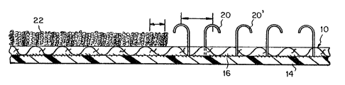
Referring now initially to Fig. 1. there is
illustrated the self-engaging separable fastener 10 of the
invention having a first loop section 12 defined by a base
member 16 having a plurality of upstanding multifilament
loop-like elements 18 and an adjacent hook section 14 defined
by a continuation of the same base member 16 having a
plurality of upstanding hook-like elements 20. The base
member 16 is common to both sections 12 and 14 and the loop-
like elements are formed by interweaving a plurality ofmultifilament loops into the base member 16 so as to be
upstanding therefrom, while the hook-like elements are formed
by simultaneously interweaving a plurality of monofilament
loop elements into the base member 16 upstanding therefrom.
Thus the multifilament loops and the monofilament loops are
woven into the base member 16 while it is being formed and
thereafter the surface is napped to separate the individual
~)77~;'3
multifilaments of fine yarns which form the multifilament
loops so as to provide a thick, plush surface. Also, the
monofilament loop elements 20 are cut to form upstanding
monofilament hooks 20' as shown in Fig. 2 so as to be
suitable for engagement and disengagement with the plush
surface of fine filament loops.
Referring once again fo Fig. 2 there is illustrated the
self-engaging separable fastener 10 of Fig. 1 taken along
lines 2-2 of Fig. 1. In this Fig. there is illustrated the
fastener 10 having woven base member 16 and monofilament hook
elements 20' which have been cut from monofilament loops 20.
For convenience of illustration only one example of the
monofilament loops 20 in its condition prior to cutting is
shown in Fig. 2.
The self-engaging separable fastener is preferably
constructed of any combination of synthetic yarns such as
nylon, polyester, polypropylene, or the like; however
depending upon the end use and particular needs any
combinations of such yarns -- or even alternative suitable
equivalent yarns -- may be included in the fastener. For
example, for certain properties which may be desired, or for
environmental reasons, the base member may be constructed of
polyester, while the hooks and loops may be constructed of
nylon, polypropylene or the like, or vice versa.
Referring now to Fig. 3, there is illustrated a
typical application of the self-engaging fastener of the
invention, namely as a fastener for an article of footwear
such as shoe 24. In this application a strip of the woven
self-engaging fastener 10 has laminated to the rear surface
of the base member 16, a suitable layer 28 of leather, vinyl
or the like. The material selected will normally depend upon
the material of the main product 24 (in this case, the
~X~,7~77~
--10--
article of footwear). The combination strap 30 is adapted to
be attached to the shoe 24 by buckles 32 and 34. Thus when
the strap is attached to buckle 32 and looped through buckle
34 it may be pulled tightly SG as to fasten the shoe and
thereafter the hook section may be pressed against loop
section 14 to maintain the shoe in tightly fastened condition
as illustrated in Fig. 4. The potential applications of the
present invention are legion and will be readily apparent to
one skilled in the art. For example, such industries as the
garment industry, the luggage industry, the automobile
industry, etc., will find this fastener to be readily
applicable to their needs due to its composite structure
which uniquely provides readily available fastening
capability of both sections without the need for stitching,
ultrasonic attachment, glueing, etc.
Referring now to Fig. 5 there is illustrated a
preferred construction of the separable fastener member 10.
In the construction illustrated in these Figs. the warp yarns
36 are shown extending approximately vertically as the fabric
emerges from the loom and the weft yarns 38 are shown
generally horizontally as they emerge from the loom. We have
found that when the same construction is used for both the
hook section and the loop section the density of hooks is too
great to permit proper penetration of the hooks into, and in
engagement with, the loops. However, by uniquely
simultaneously constructing the loop section to have greater
density than the hook section --over a common base member--
we have discovered that the proper penetration of the hooks
into the loops will take place and will provide proper
securing of the two sections of the fastener. This is
particularly accomplished by the construction as shown in the
Figs. and as will be described hereinbelow.
1~2ti~ 3
Referring now to Fig. 6 in conjunction with Figs. 7
and 8 the loop section 14 and the hook section 12 of fastener
lO are illustrated. The fastener is woven on a suitable
weaving loom which is adapted to interweave multifilament
loops 18 and monofilament loops 20 (eventually to be cut to
form hooks 20'). The multifilament loops are preferably
constructed so as to repeat their direction and construction
every four picks (i.e. every four wefts) and the monofilament
loops 20 are preferably constructed to repeat their direction
and construction every eight picks ~i.e., every eight wefts).
Thus the result of such weaving construction is that the hook
section is less dense than the loop section; or expressed
otherwise, the multifilament loops per unit length along the
warp direction is approximately one-half the number of
interwoven monofilament loops per unit length along the warp.
Broadly stated, however, our invention contemplates a
construction where the monofilament loops repeat their
direction and construction every predetermined number of
picks, whereby the number of picks for such occurrence for
the monofilament loops is greater than the number of picks
for which the multifilament loops repeat their direction and
construction. Within such definition, any combination of
respective repeat patterns may be developed, provided that
the density of the multifilament loops is greater that the
\ density of the monofilament hooks, and the proper relative
lengths of the loops and the hooks is selected.
Referring now to Fig. 6 there is illustrated the
weave pattern of both hook section 12 as viewed along lines
7-7 of Fig. 6. In Fig. 8 there is illustrated the weave
pattern of the multifilament loop section 14 as viewed along
lines 8-8 of Fig. 6. In the preferred construction shown--
i.e., multifilament loops repeat their direction and
construction every four picks and monofilament hooks repeat
73
-12-
their direction and construction every eight picks -- the
monofilament hooks tend to become interwoven by a "W" weave,
whereas the multifilament loops are more tightly woven into
the base member. In order to more properly secure all of the
members -- multifilament loops as well as monofilament hooks
-- in accordance with the method of the invention an adhesive
coating is applied to the rear surface of the base member
after the fabric is heat set to stabilize the construction as
will be described hereinbelow. Such adhesive may be a
suitable water based or solvent based adhesive, depending
upon the intended end use.
Referring to Fig. 10 the method of producing a
self-engaging fastener according to the invention is
illustrated in schematic block diagram form. Loom 36 has
introduced thereto, base yarns 16', monofilament yarns 18'
(for hooks) and multifilament yarns 20' (for loops). The
fastener fabric is formed on the loom with base 16 woven from
yarns 16', which base is common to hook section 18 and loop
section 20. The loom is suitably equipped for such
simultaneous weaving operation by incorporating the
appropriate harnesses and camming devices.
After weaving, the fabric is subjected to a
scouring process during which the weaving oils and other
cGntaminants are removed. Thereafter the fabric is subjected
to appropriate heating at a temperature sufficient to heat
set both the upstanding multifilaments and monofilaments and
the base member to stabilize the upstanding loops and the
base member and thereby improve the tightly woven grip which
the woven base member retains on the loops. After
heatsetting, dyeing of the fastener fabric is optional. The
fabric is then subjected to a napping procedure in which the
upstanding loops are subjected to the action of a rotating
wire brush which separates the various filaments of the
l;~ti7~73
multifilament loops to provide a plush, thick surface of fine
filament loops. It has been found, however, that
notwithstanding the fact that the monofilament loops (i.e.,
to be cut to form hooks) and the multifilament loops are on
the same surface, the napping brush does not adversely affect
the monofilament loops. Accordingly, for convenience both
surfaces may be subjected to the same napping operation to
which fastener fabrics having multifilament loops alone are
subjected.
After napping, the rear surface of the base member
16 is coated with an adhesive material to further stabilize
the base member as well as to increase relatively tight hold
which the base weave has on the upstanding members.
Thereafter, the fabric is subjected to a hook cutting
operation in which the monofilament loops 20 are cut as shown
in Fig. 2 to form monofilament hooks 20'. As noted
previously, the finished fastener tape may be attached
directly to an end use product or it may be provided with an
additional backing material such as a leather, vinyl, canvas,
etc. backing member which would be laminated or otherwise
attached to the rear surface of the base member for use in
securing end use articles such as footwear as shown in the
manner illustrated in Fig. 3. As noted, other potential
applications are legion.
Referring now to Fig. 9 there isillustrated a
preferred technique for cutting our fatener fabric into
fastener straps of lesser width and of efficient construction
which maximizes the use of the hooks and the loops. For
example, in footwear applications as shown in Fig. 3, it is
only necessary to include a hook seciton of shorter length
than the loop section. Thus as shown in Fig. 9, the width of
the loop section as seen on the loom is greater than the
width of the hook section. Thereafter by cutting the
'7'7'~3
-14-
fastener member -- as shown -- into relatively narrow strips
oriented at an acute angle ~A~ with respect to the side
edgesr the resulting fastener straps 40 will have a loop
section 42 greater in length than the hook section 44. This
arrangement is often desirable, as it facilitates sufficient
securement and adjustability by permitting the user to
readily tension, and press and peel the hook section at
predetermined locations along the loop surface, depending
upon the degree of fastening tension desired in a given 11
application.