Note: Descriptions are shown in the official language in which they were submitted.
~ XI~i'7856
COMPR~SSOR DRIVE WITH OIL DISTRIBUTION_SLEEVE
This invention relates to a compressor drive which
controls the driving connection between a vehicle engine and
an air compressor, and, more particularly, relates to an oil
distribution control mechan~sm for such a compressor dxive.
Large commercial vehicles have been equipped with brakes
actuated by compressed air for many years. The compressed air
used to operate the braking system of these vehicles is
supplied by a vehicle air compressor which is driven by the
vehicle engine. Since commercial vehicles often travel long
periods of time without requiring a brake actuation, operation
of the air compressor is not necessary for significant periods
of time. Accordingly, it is desirable to equip such vehicles
with a compressor drive that disconnects the air compressor
from the driving connection with the vehicle engine when
compressed air is not needed. Such a drive is disclosed in
commonly owned U.S. Patent No. 4,573,561 of March 4, 1986. The
drive disclosed in this application includes clutch plates
which are immersed in an oil bath and which are driven into
~0 and out o~ dr1ving engagement with one another in order to
couple and uncouple the air compressor ~rom its driving
connection with the engine. The ~resent invention relates to
an improvement of the device disclosed in the above-identified
application, and provides a mechanism for controlling flow of
lubricating oil to the clutch plates so that the clutch plates
are properly lubricated without consuming so much lubricating
fluid that the air compressor itself is starved for lubricating
fluid.
LCM:jj
~q~
e7
~26i7~S~
la
Broadly speaking the present invention provides drive
mechanism for establishing and releasing a driving connection
between a vehicle air compressor and a vehicle engine, the air
compressor having a crankshaft having an output drive spindle
projecting from the compressor for mounting the drive
mechanism, the drive mechanism including input drive means of
providing a driving connection with the vehicle engine, clutch
plates mounted on the output drive spindle and on the input
drive means, and actuating means for driving the ~.lutch plates
into driving engagement with one another, the clutch plates
and the air compressor both being lubricated ~y lubricating
oil communicated through passage means extending through the
crankshaft, the improvement comprising means for communicating
lubricating oil from the passage means to the clutch plates,
: the communicating means including means for limiting the rate
of flow of lubricating oil to the alutch plates to thereby
assure that sufficient lubricating oil communicates through the
passage means to lubricate the air compressor~
Other features of the invention will become apparent
with reference to the following description and drawings, in
which:
Figure 1 is: a schematic 111ustration Or a compressor,
vehicle engine, drive mechanism, unloading device, and a
reservoir showing the connections therebetween:
LCM:jj
~.
~ 7~356
--2--
~ igure 2 is a transverse cross-sectiorlal view of
the drive mechanism made pursuant to the teachings of our
present invention; and
Figure 3 is a fragmentary view of the
circumscribed portion of Figure 2, but illustrating a
different embodiment of our invention.
Referring now to the drawing, an air actuated
clutch drive mechanism generally indicated by the numeral
10 provides a driving connection between a vehicle engine
12 and a vehicle air compressor illustrated schematically
at 14. The output of the compressor 14 is communicated
via air line 16 to charge a reservoir 18. A convent;onal
unloading mechanism 20 is responsive to the pressure
level in the reservoir 18.~ The unloading mechanism 20
communicates a pressure signal through a pressure linè 22
to the port 24 of the drive mechanism 10 when the
pressure level in the reservoir 18 a~ttains a
predetermined level.
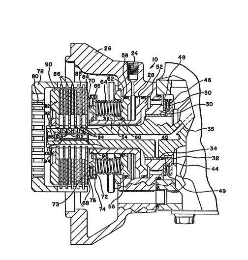
The drive clutch mechanism 10 ;includes a housing
26 which defines a bore 28 therewithin which communicates
with the inlet port 24. The end of -the bore 28 is
defined by a web 30 through which an aperture 32
extends. The aperture 32 supports a bearing 34 which in
turn supports an outlet drive spindle 36. The output
drive spindle 36 is a projecting stub portion of a
crankshaft 35 of the air compressor I4. The crankshaft
35 includes internal passages 40 to communicate
lubricating~ oil from the engine to the compressor and to
the bearing 34 and other drive components.
A bearing race 44 of a thrust bearin~ generally
indicated by the numeral 46;is mounted on the spindle
;~ ~ 36. The thrust bearing 46 further includes another~ ~ ;
bearing race 4a which engages the web 30 and cooperates
with roller cage 49 in the~b~earing race 44 to retain
circumferentially spaced rollers 50.
An annular piston 52 is slidably mounted in the
bore 28 and includes axially extending portion .~4 which
extends coaxially with the output drive spindl~e 36 and
:
~7~5~
--3--
the aperture 32. A circumferentially extending annular
retaining member 56 is received in the bore 28 coaxial
with piston 52 and output drive spindle 36. A seal 58
provides a sealing connection between the retainer 56 and
the wall of the bore 28, and another seal 60 provides a
sliding and sealing connection between the retainer 56
and the axially extending portion 54 of the piston 52.
The retainer 56 includes a depressed portion 62 which
acts as a spring retainer for circumferentially spaced
10 springs 64. The springs 64 bear against bearing race 66
of a thrust bearing generally indicated by the numeral
68. The thrust bearing 68 further includes a
circumferentially extending bearing race 70 rotatably
engaged with the clutch plate 84 adjacent the bearing 68
- 15 which the rollers 72 engage. A roller cage 73 and
rollers 72 are retained to the bearing race 66 by a
retainer 74 which is carried on the outer diameter of the
bearing race 66 and includes a lip 76 which wraps around
the outer diameter of the roller cage 73 to thereby
assure movement of the roller cage 73 with the bearing
race 66 during axial movement of the thrust bearing 68,
as will hereafter be described.
Clutch drive mechanism 10 further includes an
input drive mechanism or gear generally indicated by the
25 numeral 78 which i5 provided with internal teeth 80 which
mesh with corresponding teeth on the accessory drive of
the vehicle engine 12. I'he gear 78 is connected to the
output drive spindle 36 through a disc clutc~ pack
generally indicated by the numeral 82. The disc pack 82
3 includes clutch plates 84 which are mounted fcr a~ial
sliding movemeht along the output drive~ ~ 36 on
splines 85 formed thereon. D~sc pack 82 further includes
clutch plates 86 which are carried on splin~s 88 on the
input drive mechanism or gear 78. ~ disc endplate 90 is
mounted on the splines 85 and retained in place by a
retaining ring 92 and shimmed as at 94 to assure proper
engagement of the disc pack 82.
The portion of the lubricating passage 40 in the
7~3S~;
~) U 7~o 4 ~ Jr ~ v~ct//e 4
~b-psrt~h 36 of the crankshaft 35 receives a sleeve 96
in the end thereof upon which the clutch plates 84 are
slidably mounted. The portion of the outer
circumferential surface of the sleeve 96 between the end
portions thereof is of a diameter smaller than the
diameter of the passage 40 in which it is received to
define an annulus lO0 therebetween, and the end portions
of the sleeve are substant,ially the same dia~eter as the
passage 40 to provide a substantially fluid-tight
connection therebetween. A flow-restricting orifice 102
permits limited communication fro~l the lubricating
passage 40 into the annulus lO0. A s:eries of apertures,
or openings lO4 extend radially through the wall of the
stub portion 36 to communicate the annulus lO0 with the
` 15 clutch plates 84, 86. It will be noted from Figure 2
that there is a passage 104 for each set of clutch plates
84, 86, and the corresponding passage 104 is in
substantial axial alignment with its corresponding clutch
plates 84, 86. Accordingly, lubricating fluid can be
communicated directly from the lubricating passage 40
through the orifice 102 and the annulus lO0 to each of
the passages 104, which communicate lubricatir1q fluid
directly to a corresponding set of clutch plates 84, 86.
The embodiment of Figure 2 of the invention i.s used in a
clutch drive used with a compressor in which lubricating
oil is fed directly from the engine to the left end
(viewing Figure 2) of the crankshaft and into the
lubricating passage 40. Fluid is then communicated to
the compressor through the passage 40. In some
compressor installations, lubricating oil is ~ed from the
engine through conduits or hoses (not shown) and then
backfed toward the engine through the lubricating passage
40. The embodiment of Figure 3 discloses a sleeve ~ :
used in such a backfed co~pressor in w71ich the left hand
end of the s:Leeve is solid to close the lubrication
passage 40. In all other aspects, the operation and
function of the lubricating sleeve 96 is identical to
that of Figure 2.
~2~;7~
--5--
In operation, fluid communicated through the
lubricating passage 40 is communicated through orifice
102 into the annulus 100. Because the size of the
orifice 102 is restricted, fluid cannot flow into the
annulus 100 in sufficient quantities such that the
various internal components of the associated air
compressor are starved for lubrication. Accordingly,
passages 104 may be of sufficierlt size that they may be
drilled economically, and a sufficient number of
lubricating passages 104 can he provided to service each
of the clutch plates 84, 86 without providing 50 large a
flow area that lubricating fluid could be communicated
through the clutch plates while starving the internal
components of the air compressor for lubrication.
The conventional unloader mechanism 20, which is
well known to those skilled in the art, maintains a
pressure signal in the air line 22 whenever the pressure
load in the reservoir 18 exceeds a predetermined level.
I'he pressure signal in the air line 22 is communicated
through the inlet port 24 into the bore 28, where it acts
upon the piston 52, urging the latter to the riyht
viewing Figure 2 or from the position illustrated.
Movement of the piston 52 to the right viewing Figure 2
also carries the thrust bearing 68 in the same direction,
away from the clutch disc pack 82 and compressing the
springs 64. When the force or load on the disc pack 82
is relieved, the clutch plates 86 can rotate relative to
the clutc}l plates 84, so that the driving connection
between the input drive mechanism or gear 78 and the
output dr;ve spindle 3G is broken. When the pressure
level in the reservoir 18 drops below the precletermined
level, the unloading mechanism ven~s the pressure line
22, thereby exhausting the flu;d pressure level in the
bore 28. When the pressure in bore 28 acting against
piston 52 is exhausted, the springs 64 yieldably urge the
thrust bearing 68 to the left viewing Figure 2, -thereby
driv;ngly engag;ng the clutch plates 84 with the clutch
plates 86. Accordingly, the springs 64 maintain the load
3 ;2~7~5~
_.
-6-
on the clutch disc pack 82 against the clutch end plate
90, thereby permitting the inpu-t drive mechanism or gear
78 to drive the compressor 14 through the output drive
spindle 36.
:
. :
~ :
:
:
:
:
: :
,
::
: :
: