Note: Descriptions are shown in the official language in which they were submitted.
Il`lPROVE~E~3TS Ii~ OR RELATING TO ELECTRIC
RADIATI0~3 HEATER ASSEMBLIES
.
The present invention relates to electric radiation heater
assemblies for glass ceramic top cookers.
05 It is known that the use of heating elements with high
operating te~peratures, such as infra-red lamps, in glass
ceramic top cookers gives rise to an irnproVeMent in cooking
performallce as a result of improved radiant heat transfer,
fast response to changes in control settings and visual
feedback of the control setting. However, because of the
large positive temperature coefficient of resistance
associated with infra-re~ lamps, the initial or inrush
current is very high and this can cause problems such as
tripping of magnetic circuit breakers and ~ains
disturbances.
In order to reduce these problems it is known to connect a
bare wire resistance coil, known as a ballast coil, in
series with the infra-red lamp or lamps. If the power
consumed by such a ballast coil is significant, i.e. more
thall a few per cent of the total power consuMed by the
heater, it is considered essential to position the ballast
coil within the body of the heater. In practice, the power
consumed by the ballast coil is typically one third of the
~Z67~7
total power. This eliminates the problems with magnetic circuit
breakers and reduces mains disturbances to an acceptable level with
relatively low power heaters i.e. up to about 1500 watts. However,
higher power heaters can still result in unacceptable disturbances
to the mains electricity unless the resistance of the ballast coil
is increased, but increasing the resistance o~ the ballast coil
reduces the advantages of using infra-red lamps because it reduces
the proportion of the power of the heater generated by the lamps.
It is an object of the present invention to provide a radiation
heater assembly for a glass ceramic top cooker which incorporates
a heating element having a substantial positive temperature
coefficient of resistance and a ballast coil and which does not
result in unacceptable disturbances to the mains electricity.
According to the present invention there is provided an electric
radiation heater assembly comprising: at least one heating element
having a substantial positive temperature coefficient of
resistance; a resistive assembly electrically connected in series
uith said at least one heating element for suppressing surge of
electric current due to said at least one heating element, said
resistive assembly comprising two resistive elements electrically
connected in parallel; means for supplying electric power to said
at least one heating element and to said resistive assembly; and
suitch means operable a time interval of at least thirty milli-
seconds after a supply of electric power to said at least one
heating element and to said resistive assembly is energised such
that one of said resistive elements is electrically open-circuit
~6;7~ 7
until said ~ime interval has expired and is thereafter
electrically connected in parallel with the other of said
resistive elements so as to reduce the combined elec~rical
resistance of said at least one heating element and o~ said
05 resistive assembly.
The heater assembly may comprise two heating elements and
the or each heating element may comprise an infra-recl lamp.
The resistive assembly may comprise a single resistive
element which may be positioned within or externally of the
body o~ the heater, the resistive element being
electrically short-circuited after said time interval.
Alternatively, the resistive assembly may comprise two
resistive elements èlectrically connected in parallel, one
of said resistive elements being electrically open-circuit
until said time interval has expired.
The switch means may comprise a relay including an
actuating coil which is connected across said at least one
heating element. Alternatively, the switch means may
comprise a PTC thermistor in combination with a bi-metallic
snap switch.
The time interval may be from 30 milliseconds to 10
seconds, but is preferably about 1/2 second.
.~
~æ~73~
--4
For a better understanding of the present invention and to
show more clearly how it may be carried into effect
reference will now be made, by way of example, to t~le
accormpanying drawings in which:
05 Figure 1 is a diagramr~atic illustration of one er.lbodirnell
of a circuit diagram for a radiation heater according to
the present invention;
Figure 2 shows a radiation heater according to the present
invention and incorporating the circuit depicted in the
circuit diagram of Figure l;
Figure 3 is a diagrammatic illustration of a second
embodiment of a circuit diagram for a radiation heater
according to the present invention;
Figure 4 is a diagrammatic illustration of a third
embodiment of a circuit diagram for a radiation heater
according to the present invention;
Figures 5,6 and 7 are circuit diagrarns of further
embodiments of the present invention; and
Figure & is a diagrammatic illustration of an embodiment of
a circuit diagram for a radiation heater according to the
present invention and incorporating a PTC thermistor.
Z7
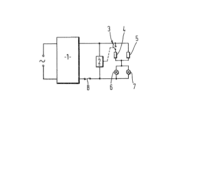
The circuit depicte~ by means of the circuit diagram shown
in Figure 1 cormprises an energy regulator 1, a time delay
means 2 which is connected to t~e output side of the energy
regulator 1 and w~lich operates a switch 3 a predetermined
05 time after each occasion t}le energy regulator permits
electric current to pass t}lerethrouy~, a pair of resistors
4,5 each in the form of a coil of bare resistance wire, a
pair of infra-red lamps 6,7 which are electrically
connected in parallel, and a thermal cut-out device 8.
lQ In operation, the energy regulator 1 is moved from an "off"
position to an infinitely variable ~on" position in which
for higher settings the energy regulator permits electric
current to pass therethrough for a greater proportion of a
given period. Once the energy regulator is moved to an
~on~ position electric current passes through the energy
regulator to the time delay means, to the switch 3 and to
one of the resistors 5. Current flows through the resistor
5 through the lamps 6,7 which are connected in parallel and
back to the energy regulator 1. After a predetermined
time, the time delay means 2 operates to close the switch 3
and thus allows current to pass through resistor 4.
Because resistors 4,5 are now connected in parallel this
effectively halves their combined resistance and causes the
electric current flowing through the lamps 6,7 to increase.
He have found that the time delay may vary considerably.
~Z~ %'7
However, if the time delay is very short, i.e. less than 30
milliseconds, the lamps will effectively be energised
simultaneously thus not reducing any mains disturbance that
might arise, whilst if the time delay is much more than 10
05 seconds one of the resistors 4 will be energised for a
significantly shorter period than the other resistor at low
settings of the energy regulator. In practice, we have
found that a time delay of about 1/2 second is to be
preferred.
The radiant heater shown in Yigure 2 embodies the circuit
diagram of Figure 1 and comprises a dish 10, for example
pressed from sheet metal, which contains a base layer 11 of
thermal and electrical insulating material and a peripheral
wall 12 of thermal insulating material. A helical coil of
bare resistance wire is arranged on the base layer and
extends substantially in a circle adjacent to the
peripheral wall 12. The coil is centre-tapped to form two
resistance elements 13,14.
A thermal cut-out device 15 extends across substantially
the centre of the dish 10 and comprises a temperature
sensor 16 connected to a switch 17. In the event that the
temperature sensor 16 detects an excessive temperature the
switch 17 is actuated to de-energise the heating elements.
~26~7~
until such time as the temperature has dropped to an
acceptable level. Two infra-red lamps 18,19 extend across
the dish 10, one lamp being positioned on each side of the
temperature sensor 16.
05 A.C. power is supplied to the resistance elements 13,14 and
to the infra-red lamps 18,19 by way of an energy regulator
20 and, in the case of resistance element 13, a switch 21.
Switch 21 is connected to a time delay mechanism 22.
For a heater rated at 1800 watts at 220 volts, the lamps
18,19 are typically rated at 600 watts at 147 volts each,
with the resistance elements 13,14 rated at 17.9 ohms each
with the resistance wire at its operating temperature.
This arrangement results in approximately 67 per cent of
the energy being derived from the infra-red lamps 18,19.
The circuit depicted by means of the circuit diagram shown
in Figure 3 comprises an energy regulator 31 and a time
delay means 32 which is connected to the output side of the
energy regulator 31 and which operates switches 33,34 a
predetermined time after each occasion the energy requlator
Permits electric current to ~ass therethrouqh. A resistive
assemblv comDrises a Dair of resistors 35.36 each in the
form of a coil of bare resistance wire which are connected
with the switches 33.34 so as to he electricallv connected
7 ~7
in series and in Parallel as will be exP3ained in more
detail hereinafter. A Pair of in~ra-red lamPs 37,38 are
electrically connected in Paralle1 with each other and in
series with the resistive assemblY. A thermal cut-out
05 device 39 is electrically connected in series with the
lamPs 37.38 for ~reventinq excessive temPeratures.
OPeration of the circuit deDicted in Fiqure 3 is similar to
the oPeration of the circuit dePicted in Fiqure 1 excePt
that initiallv the two resistors 35,36 are connected in
ln series and the delaY means 32 operates switches 33.34 to
connect the resistors 35,36 in Parallel. This arranqement
has the advantaqe of incr~asina the initial resistance
com~ared with the circuit deDicted in Fiqure 1, but a
double-Pole chanqe-over switch is required and the switches
are required to break a current and will therefore need to
be heavier dutY.
~he circuit dePicted in Fiqure 4 comPrises an enerqv
requlator 41 and a time delav means 42 which is connected
to the outPut of the enerqY requlator and which oPerates
switch 43 a Dredetermined time after each occasion the
enerqy requlator Permits current to ~ass. When the enerqY
requlator is conductive electric current Passes throuqh
resistor 45, infra-red lamP 47. and thermal cut-out device
48 and after a Predetermined delay switch 43 is closed and
~267~Z~
causes resistor 44 and lamp 46 to be connected in parallel
with resistor 45 and infra-red lamp 47. Thus the lamps
~6,47 are energised separately whic~l further suppresses the
inrush current, but two separate resistors are required
05 rather than a single centre-tapped resistor.
The circuit diagrams of Figures 5,6 and 7 show three
practical e~bodiments of t~le present invention. Sirnilar
parts in Figures 5,6 and 7 are denoted by the same
reference numerals.
Figure 5 shows an eneryy regulator 51 which is electrically
connected with heating elements in a heater dish 52 by way
of a thermal cut-out device 53. In each embodiment the
heating elements include two infra-red lar,~ps 54, although
in the embodiment of Figure 5 two coils 55 of resistance
wire are also provided and in the embodiment of Figure 6 a
single coil of resistance wire is provided.
In the embodiments of Figures 6 and 7 a resistive element
56 is provided externally of the heater dish 52.
The electrical voltage across the infra-red lamps 54 is
passed to a rectifier 57 by way of a resistor 58. The
2G rectified voltage is applied to the coil S9 of a relay
which incoryorates a switch 60.
~6i7~;~7
--10--
In the embodiment of Figure 5, applying voltage to the
relay coil S9 causes the relay switch 60 to close. This
results in the coils 55 being connected in parallel an~
thus reduces the combined resistance of t~le coils 55 and
05 the infra-red lamps 54.
In the embodiments of Figures 6 and 7, applying voltage to
the relay coil 59 causes the relay switch 60 to close and
thus to short-circuit the external resistive element 56.
This also reduces the combined resistance of the resistive
element 56, the coil 55 (in Figure 6) and the infra-red
lamps 54. Because electric current passes through the
resistive element 56 for only a short time, the average
power consumed by the resistive element 56 over a
substantial period is small and thus the resistive element
does not generate a significant amount of heat externally
of the body of the heater and can be a relatively low-rated
component.
Although the typical operating time of a small relay is of
the order of lO to 20 milliseconds and thus too short in
itself, we have found that when the energy reyulator 51
becomes conductive the voltage across infra-red lamps 54
does not rise immediately to its equilibrium value.
Arranging the actuating coil 59 of the relay across the
infra-red lamps thus incorporates the delay due to the
~6 ~ ~27
voltage rise into the overall delay thus bringiny the
overall delay to at least 30 milliseconds.
As an alternative to the use of a relay, the embodiment
shown in Figure 8 employs a switch means which comprises a
05 PTC thermistor 62 and a snap-switch 63, althouyh electronic
delay means (for example based on a capacitor-resistor
circuit) and/or electronic switching (for example based on
triacs) oay also be used. The thermistor 62 is connected
across resistor 5 which effectively reduces the operating
voltage when the snap-switch 63 is closed and thus
increases the reliability of the thermistor. It is also
possible to employ two PTC thermistors in combinatiorl with
a relay.
With reference to Figure l,2 and 4 to 8, a suitable NTC
thermistor would permit the functions of the
relay/snap-switch and the delay means ~o be combined.
The switch means may be an integral part of a terminal
block which supplies electric current to the heating
elements within the heater or may be mounted within the
cooker hob or its control unit as a separate assembly.
Although the present invention has been described in
conjunction with an energy regulator, it is possible to use
12 ~79~7
a multi-position switch by means of which the heating
elements are energised in a number of different
configurations.