Note: Descriptions are shown in the official language in which they were submitted.
126~33~1~
~ he present invention relates to a proce3s for pur-
ifylng nltrogen-and-sulphur-oxides-containing Elue gases from
tncinerators, i.e., a process that is simplified with regard
to the prncedure and the capital expenditure for equipment.
Nitric oxides and sulphur oxides forming ln combus-
tion processes are some of the principal causes of acid raln
and photosmog and thus of environmental damage associated
therewith. Therefore, they should be substantially removed
from the flue gases prior to their escape into the environ-
ment.
Sources of the emissions of nitric oxide and sulphuroxide are motor-vehicles, stationary internal combustion
engines, power plants, heating power plants, steam generators
for industrial purposes and industrial production plants.
Carbon monoxide and hydrocarbons are also emitted by some o
these sources of deleterious substances.
By using fuels low in nitrogen and sulphur as well
as by suitable additions to the fuel or modifying the combus-
tion sys-tem a reduction in the concentration of deleterious
substances in the flue gas can actually be attained but these
primary further procedures have technical and economic limita-
tions so that heretofore it was not possible to obtain flue
gases sufficiently free from nitric oxide and sulphur oxide.
Flue gases, for example, from furnaces using fossii
fuels or internal combustion engines operated above-stoichio-
metrically, i.e., lean-adjusted, contain excess oxygen in
addition to oxides of nitrogen and sulphur.
Heretofore, the denitrificat1on and desulphurization
of these flue gases was usually carried out in separate pro-
cess stages, which are i~stalled at different points of theflue gas path. Conventional processes for the combined deni-
trification and desulphurization are still very costly and -~
~2~ 8
have many clisadvantayes. ThereEore, for the appllcation on a
large :lndustrial scaLe processes with separate denitriElcation
and desulphurlzation are still preferred at present.
The reduction of nitric oxides in furnaces is usu-
ally carried out by catalytic reduction. In order to assure
optimal utllization of the required reducing agent, primarily
selective reducing processes are suitable for the removal of
the nitric oxides, because of the oxygen component in the flue
gas. It has been found that ammonia gas, which, on a suitable
catalyst, readily reacts with the oxides of nitrogen but only
to a minor extent with the oxygen, is a suitable reducing
agent.
In con-trast to the denitrification non-catalytic wet
processes have been accepted for the desulphurization to a
great extent. In the process most frequently used the sulphur
dioxide present in the flue gas is first oxidized with atmo-
spheric oxygen to sulphur trioxide, when required after pre-
ceding wet absorption. Simultaneously or subsequently it is
treated with a suspension of calcium hydroxide, calcium car-
bonate or calcium oxide. The gypsum obtained must elther be
deposited for waste disposal or lt can be used in the building
material industry aEter preceding processing.
In power plants with furnaces the followlng flue gas
purification concepts are at present used:
1. Catalytic denitrification in the "hot" flue gas portion~in
the high dust content region and desulphurization after free-
lng the flue gas from dust by converting the sulphur dioxide
into gypsum.
For this purpose an ammonia/air mixture is homogeneously
distributed in the flue ~as flow immediately after the boiler~
The reaction mixture then passes a denltrification catalyst,
which is kept at approximately 370 to 400C. In a subsequent
3~L~
heat exchanger heat is removcd from the fluo gas. Thi~ heat
:ls used~ :Eor example, Eor preheating the a:lr o~ combustiorl ~or
the boiler. The flue gas is then freed ~rom dust. The sub-
stantially dust-free flue gas, which still contains sulphur
dioxide, is reacted in the flue-gas desulphurization plant
with atmospheric oxygen and a suitable calcium compound to
gypsum. The flue gas thus purified is discharged into the
environment via a chimney.
2. Desulphurization as in concept 1 and catalytic denitrifi-
cation in the ~cold" flue gas portion in the low-dust content
region.
For this purpose heat is removed in a heat exchanger from
the flue gas on leaving the boiler, whereupon the flue dust is
separated. This is followed by the desulphurization of the
flue gas. It is carried out according to the same process
principle as in concept 1. By means of a further heat
exchanger the flue gas is preheated with the flue gas leaving
the denitrification process and in a series-connected heating
device, which, for exampIe, burns natural gas in the flue gas
flow (supporting fuel), it is heated to the reaction tempera-
ture required for the denitrification. The flue gas thus
heated is then mixed with the reducing agent ammonia, where-
upon it passes the denitrification catalyst. The nitric
oxides are selectively reduced thereon to nitrogen and water
vapour. The denitrified flue gas is then recycled to the heat
; exchanger, wherein the flue gases coming from the desulphur-
ization plant are preheated. They pass this heat exchanger
and flow into the chimney.
However, these two flue-gas purification concepts
have a number of disadvantages which have a detrimental effect
on the operation of furnaces.
In fact the catalytic denitrification according to
i83~i5
concep-t 1 has the ac3vantage thak .l.n full-load ope~at:l.on a e:Lue
gas temperature of 350 to ~00C can be a~tained. ~'hey are
temperatures at which known denitrification catalysts can be
operated. However, in a load reversal operation, which is
very frequently the rule in German power plants, the flue gas
temperature ~n the partial load range usuall.y drops below the
minimum required for the operatlon of the catalyst so that an
expensive by-pass connection for branching off flue gas prior
to the last heat-removal stage in the boiler would be neces-
sary in order to maintain the reaction temperature.
Furthermore, the method of operation in the region
of high dust content results in abrasions of the catalyst due
to the flue dust and can cause deposits and thus clogging of
the catalyst ducts and pores. Consequently in order to pre~
vent this cleaning by blasting, for example r with hot steam,
must be carried out at relatively short time intervals.
In any denitrification plant operated with ammonia
there is encountered the additio~al problem that this reducing
agent is not completely reacted and that a small amount ;~
thereof, known as ammonia slippage, is present in the flue gas
after the denitrification plant. Because of reactions between
ammonia and the sulphur oxides present in the flue gas this
results in corrosive and sticky deposits of ammonium hydrogen
sulphate and/or ammonium sulphate, for example, on the heat
exchange surfaces of the air preheater. The washing of the
air preheater which thus is periodically required causes an
effluent problem. Furthermore, the dust from the dust
arrester and the gypsum from the flue gas desulphurlzation
plant are contaminated and render a further utilization or
their removal difficult. Ammonia escaping from the chimney
results in an additional burden on the environment.
According to the second concept, the flue gas passed
-- 4
~26~3~.~
over the denltri:Eication catalyst actually contains only small
amounts of dus-t and sulphur di.oxide. I;'or tho ~unc~ion o~ th~
denitri.f:lcatlon catalyst this is favourable per se, Howevor,
this advantage is at the expense of a number of disadvantages.
Thus, for example, after the desulphurization plant there must
be installed a gas preheater and a supporting furnace, which
is usually heated with an :lnert fuel, for example, natural
gas, i.e., primary energy. This causes additional investment
and operating costs. The problem of the corrosive ammonium
salt deposits and of effluents due to washing is also encoun-
tered in this concept. ~Iowever, the gypsum is no longer
loaded with ammonia.
The fact that the flue gas desulphurization is car-
ried out by wet means while producing gypsum is a factor which
these two process concepts have in common. In most cases
limestone, which causes additional costs, is used as working
material for this purpose. Only a fraction of the gypsum
obtained can bè sold to the construct~on industry because of
~ lack of demand, for reasons of costs or because of insuffi-
cient purity.
The present invention provides a process for purify-
ing nitrogen-and-sulphur-oxides-containing flue gases from
incinerators and industrlal production processes by selective
catalytic reduction of the nitric oxides with ammonia, subse ~;
~quent oxidation of sulphur dloxide with oxygen and conversion
of the sulphur trioxide obtained into a compound containing
sulphate ions. This process avoids the disadvantages of the
; ~ conventional processes.
In accordance with the present process, the oxida-
tion of the sulphur dioxide is carried out on a catalyst and30
the sulphur trioxlde obtained is reacted with water to form
sulphuric acid after intermediate cooling. According to a
~,
- 5 -
. . .. . . . . .. . . . .. . . .
l33~
very advantageous embodiment oE the proces,s according to the
present lnvention, reduction and ox:ldation are carrted out ln
a single reactor havlng a ~lrst section provided with the
reduction catalyst and a second sectlon provided with the
oxidation catalyst.
The denitrification and the desulphurizatlon thus
occur in that in a reactor the flue gases are brought into
contact with two different reaction-specific catalysts one
directly after the other. For this purpose, the flue gas con-
taining the deleterious substances is mixed with the gaseous
reducing agent ammonia and passed over the first catalyst
stage, in which the nitric oxides are selectively reduced at
elevated temperature.
Base metal and noble metal catalysts can be used for
this purpose. Care must be taken that no substances causing
contamination on the subsequent oxidation catalyst are dis-
charged from the first catalyst. Immediately upon leaving the
reduction catalyst the flue gas which still contains sulphur
dioxide, oxygen and in some cases carbon monoxide and/or
hydrocarbons is passed over the oxidation catalyst, in which
sulphur dioxide is converted into sulphur trioxide. Possibly
present carbon monoxide and/or hydrocarbons are simultaneously
converted into carbon dioxide. On cooling the flue gases sul-
phur trioxide is brought into contact with aqueous sulphuric
acid, for example, in a gas scrubber, and separated as sul-
phuric acid having as a high percentage of SO3 as possible.
Plants used, for example, in the production of sul-
phuric acid, are suitable for this purpose.
The reduction stage can be acted upon with flue gas
having a low dust content or being substantially free from
dust or the flue gas can~be freed from dust only after inter-
~Z6E~31~
mediate cooling and prlor to the hydra~ion of the sulphur tri~oxide. ~lowever, the emboclimen-t mentloned ~irs-k is preforred
since the mechanical and -thermal load of the cataly~t is sub~
stantially lower. For the dust removal according to the
embodiment mentioned first the use of a hiyh-temperature elec-
trofilter is particularly favourable.
The type of filter actually requires a slightly
higher investment as compared with an unheated electrofilter
but reheating measures and problems associated with the cat-
alyst abrasion are not encountered. Furthermore, the two
embodiments have the advantage that the dust removed is not
contaminated with ammonia. Since the desulphurization by
means of the process according to the present invention pro-
duces no gypsum, any waste disposal or marketing problems are
not encountered, which might result from the contamination of
the gypsum or from an offer of gypsum surplus on the market.
In the process according to the present lnvention
fundamentally any catalyst suitable for the selective reduc-
tion of nitric oxide can be used. Examples are catalysts
based on mixtures of oxides of titanium, tungsten, vanadium
and molybdenum (see DE-OS ~o. ~2,458,888) or catalysts consist-
lng of naturaI or synthetic aluminium silicates, for example,
zeolites or catalysts containing noble metals of the~platinum
group.
For the oxidation of the sulphur dioxide all the
catalyst systems customarily used are applicable. Examples
are systems listed in Gmelin, Handbuch der Anorg. Chemie. Vol.
9j Part A, Page 320 ff (1975), for example, catalysts contain-
ing platinum, vanadium pentoxide or iron oxlde.
The catalyst for the reduction of nitric oxide and
the catalyst ~or the oxidation of the sulphur dioxide can have
a honeycomb structure or the form of a dump packing. Because
~;:
- 7 -
~ 3
of the lower pressurc head arld th~ simpler poss.i.bil:lty o~
remov:lng dust the embod:l.merlt mention~d Elrst ls preferred.
One or both catalys-ts can consist of a catalytically
active mass throughout (solid catalyst) or in one or both ca-t-
alysts the catalytically active substance may be present on an
inert ceramlc or metallic body which, when requlred, ls coated
with a sl~rface-increaslng oxide layer ~catalyst support).
The two catalytlc reactlons which preferably are
carried out in a single reactor can be operated in a tempera-
ture range of 250 to 550C, preferably 350 to 450C, particu-
larly 380 to ~20C.
According to the present 1nvention the flue gas
freed from the nitric oxides and leavlng the sulphur dioxlde
oxidation stage must be sub;ected to intermediate cooling
before the sulphur trioxide formed can be reacted with water
to form sulphuric acld~ It has been found to be favourable to
cool this flue gas to a temperature of 20 to 160C, pr~ferably
70 to I50C, particularly 110 to 140C prior to the hydration
of the sulphur trioxide.
The hydration of the sulphur trioxide can be carried
out in a single-stage or multistage scrubber with a 70 to 85%
by weight, preferably 75 to 80% by weight sulphuric acld.
These plants are conventional in the technology of the sul-
phuric acid production.
It is advantageous to carry out the hydration of the
sulphur trioxide at temperatures of 40 to 130C, preferably 95
to 125C, particularly 100 to 115C.
An advantage of the process according to the present
invention lies in the compact type of construction of the flue
gas purification plant resulting from the ~oint arrangement of
denitrification and desulphurization catalysts in the pre-
ferred common reactor.
- 8 -
~2~ 3~l8
A further advantage lles :Ln tha-t khe s.l;Lppage oE
ammonia through the entire plant can he complQtoly avoid~d by
the series connec-tion o~ the oxidation catalyst since the
small amount o~ unused ammonia from the denitrification is
completely oxidized on the oxidation catalyst. The nitric-
oxide content in the purified flue thus is raised again only
slightly. All the technical problems associated with the
ammonia slippage of conventional flue-yas purification plants
are thus eliminated, as for example, the corrosion due to
deposits of amrnonium salt and stresses on the environment
caused by wash water or the emission of ammonia into the envi-
ronment.
Apart from water no chemicals are re~uired for the
desulphurization. The water can be used as such or in the
form of concentrated sulphuric acid. H2SO4 in concentrations
of 75 to 80% by weight can be continuously produced and dis-
charged. The sulphuric acid produced from the sulphur oxides
causes practically no costs ~or raw material and can be dis-
posed of easily because of its broad range of application ln
the chemical industry.
The present invention will be described hereafter in
greater detail with reference to the flow sheets of the accom-
panying drawings with a description of the function and by a
practical embodiment.
In the accompanying drawings:
Fig. 1 is a schematic flow sheet of the process
according to one embodiment of the present invention; and
Fig. 2 is a schematic flow sheet according to
another embodiment of the present invention.
Description of the Function
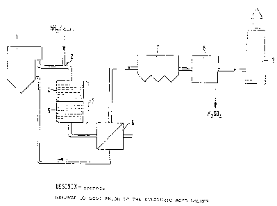
Embodiment 1: Removal of dust prior to the catalysts
According to Figure 1 the flue gases leaving the
~ 3
boller 1 are ~reed ~rom dus-t in a high-tempe~at,ure electro~
ter ~, whereupon they are mixed with a mixkure o~ ammonia anc~
air at 7. and fed into the combi-reactor ~. ~n the reactor
three layers of monolithic ceramic honeycomb catalysts 5 for
the reduction of nitric oxide are tandem ~oined in the direc-
tion of flow of the gas.
This arrangement is followed in the same reactor
housing by three further layers of monolithic ceramic honey-
comb catalysts 6 for the oxidation of sulphur dioxide. There
exists a wide clearance for dimensioning the intervals between
the individual catalysts and catalyst types. The intervals
are intended for producing a turbulent transverse movement in
the flue gas and thus for avoiding locally the so-called
stream formation.
The catalytic reactor 4 is followed by a heat
exchanger 7, for example, a plpe-assembly heat exchanger. In
said heat exchanger the denitrified gas containing the sulphur
compounds as sulphur trloxide is cooled to the lntended oper-
ating temperature of the SO3 washer. The heat thus emitted
serves for preheating the combustion air for the boiler plant.
In the gas washer 8 the flue gas is reacted with water as such
or in the form of diluted aqueous sulphuric acid and higher ,~
percentage H2SO4 is thus obtained. The washer can most
favourably be operated with a recycled sulphuric ac1d having,a
concentration close to, at,or equal to the desired final con-
centration of 75 to 80% by weight. The completely purified
flue gas leaving the washer can then be discharged into the
atmosphere via the chimney 9.
Embodiment 2: Dust removal prior to the sulphuric acid washer
According to Figure 2 the flue gases leaving the
boiler plant 1 are mixed with a mixture of ammonia and air at
2 and fed into the reactor 3. In said reacter three layers of
.
~fif~3~F~
monol:l-thic, cerarnlc honeycomb ca-talys-ts 4 are tandem ~oined in
the direction Q~ flow o~ the gas ~or the reduct:Lon oE nltric
oxide.
This arrangement is followed in the same reactor
housing by three urther layers of monolithic, ceramic honey-
comb catalysts 5 for the oxidation of sulphur dioxide. There
exis-ts a wide clearance ~or dimensloning the lntervals between
the indlvldual catalysts and catalyst types. The lntervals
are intended for producing a turbulent transverse movement in
the flue gas and thus for avoiding locally the so-called
stream formation.
The catalyst reactor 3 is followed by a heat
exchanger 6, as Eor example, a pipe-assembly heat exchanger.
In said heat exchanger the denitrified gas containing the sul-
phur compound as sulphur trioxide is cooled to the intended
operating temperature of the SO3 washer. The heat thus emit-
ted serves for preheating the combustion air for the boiler
fuel. The heat exchanger 6 is followed by the dust filter 7.
In the washer 8 the flue gas ls reacted with water
as such or~ for example, in the form of diluted agueous
sulphuric acid and higher percentage H2SO4 is thus obtained.
The washer is most favourably operated with a recycled
sulphuric acid having a concentration close to, at or equal to
.
the desired concentration of 75 to 80% by weight. The
completely purified flue gas leaving the washer can then be ~
discharged into the atmosphere via the chimney 9. ~`
Practical Embodiment
The process according to the present invention was
carried out in a plant constructed according to the embodiment
1 which had been inserted into the path of the flue gas of a
coal-fired heating power plant with heating power coupling
circuit.
"
3~8
Coal du~;t is used as ~uel in the heatin~ power plant
compr:lslng a to-tal oE three water~tube bo:L:Lers wl-th natural
circu:lation. The fuel capaciky of a boiler is 98 MW. By
means oE the heating power coupling 18 MWei and 50 MWth are
produced and emitted. The amount of flue gas per boiler is
llO000 cum ~N)/h.
The flue gas for the plant was removed after a high-
temperature filter, which was operated at approximately 450C.
Table l
Technical Data of the Pilot Plant
flue gas throughput 500 cum (N)/h
dust content in the flue gas a~ter
the electrofilter 20-50 mg/cum(N)
space velocity NOX catalyst 7500 h 1
space veloclty oxidation catalyst 7500 h l
empty tube velocity in the reactor 3 m/sec.
flue gas temperature 420-46bc
total pressure loss on the catalysts 2400 Pa
inlet temperature in the SO3 washer 130C .
operating temperature of the SO3 washer 100-110C
degree of SO3 separation of the SO3 washer >95%
final H2SO4 concentration 77-~o~ by weight
The NOX catalyst was designed as a catalyst support
consisting of mullite honeycomb bodies having the dimensions
150 mm x 150 mm x 150 mm length with a cell density of 16 per
sq. cm and a zeolite coating of the mordenite type.
The oxidation catalyst was designed as a catalyst
support consisting of mullite honeycomb bodies having the
dimensions 150 mm x 150 mm x 150 mm length with a cell density
of 16 per sq. cm and an -aluminium-oxide coating which
~ontained 2.5 g/dm3 of p~atinum in a finely divided form.
The intervals between the catalysts of the same kind
- 12 -
:~6~3~
were 160 mm an~ between two di~faren-t: cataly.sts 200 mm.
~ f-ter 2000 hours o~ oporation and at a rnola~ ra~io
of ammonia to nitric oxide of 0.9 conversion rates greater
than 94% could be determined for nitric oxide and greater than
91% for sulphur dioxide. An a~onia sllppage after the combi-
reactor was not detected in any case.
The data for the flue gas composition with the
deyrees of conversion attained have been listed in Table 2.
Table 2
Flue Gas Composition and Degrees of Conversion
flue gas concentration concentration degree measuring
component prior to combi after combi- conver- method
reactor reactor sion
.. _ . _ . ... _
NOX 380-510 vpm 20-30 vpm >94% chemi lumi-
nescense
method
S2 580-640 vpm 50-57 vpm >91% W spectros-
copy
2 7-8% by volume approximately paramagnetic
7% by volume method
NH3 340-455 vpm not detectable quanti- wet chemical
tatively absorption
and analysis
~,t
- 13 -