Note: Descriptions are shown in the official language in which they were submitted.
-- 2 --
This invention relates to camera housing units
and, in particular, a housing ùnit suitable for an
outdoor surveillance or video monitoring camera~
Although surveillance cameras and protective
housings therefor are known, various difficulties have
been encountered with existing units on the market~
particularly in connection with surveillance cameras
used outdoors. Generally speaking, expensive
surveillance cameras must be protected from damaging
weather con~itions when they are used outdoors. These
cameras are generally protected by placing them in a
housing that keeps the camera dry and free from dirt
and dust. One difficulty encountered with
surveillance cameras used outdoors arises from the
need for a surveillance camera with a lens having a
long focal length, for example 700mm. Such lenses are
ver~ sensitive to any movement of the lens and a very
sli~ht movement during the picture taking process will
make the picture unclear and even completely unusable.
If there is a wind blowing and acting on the houslng
for the camera, the vibration of the housing can be
transmitted to the camera and its lens, thus rendering
the camera useless.
Another difficulty with known surveillance
cameras arises from the use of clear plastic or
Plexiglas* to construct all or part of the housing.
~ `
~ * trade mark ~
:- ~
. . . .. :
, ~ , . , . : ,
: - : . . .. . ..
",~
-.:
.:
,
-- 3
The use of a clear material is of course necessary for
the camera to view the desired area from inside the
housing. However, plastic and Plexiglas* over a
camera lens, and particularly a very precise lens
designed to take a clear picture from a long distance,
will cause distortion of the picture and this is
particularly true after the housin~ unit has heen in
use for a period of time because hairline cracks soon
develop in the plastic material. The use o~ clear
glass would overcome this problem but up until now the
use of such material has been found to be too
expensive. It will be appreciated that if a glass
dome or hemisphere is used in a surveillance camera
system, it must itself be constructed to very close
tolerances in order to avoid picture distortion.
Although spherical housing units for
surveillance cameras are known for indoor units, they
have not been used in the past for outdoor units,
possibl~ due to the difficulty of manufacturing a
spherical unit that can withstand outdoor weather
conditions and that has the required features inside
the dome to keep the camera in good working order.
There is a distinct advantage to the use of a
spherical housing unit outdoors in that a sphere is
the best aerodynamic~shape, that is, it provides the
least wind resistance on avera~e when one takes into
~'
;~ * trade~mark
: ~ , . .. . . .
. ~
:.. ~:
654
-- 4 --
account the fact that the wind can blow from any
direction. Because of the smaller air resistance
created by the sphere, a spherical housing unit is
less likely to be damaged by high wind conditions and
will not vibrate as much as a unit of a different
shape might.
A known housing assembly for a surveillance
camera is that taught in U.S. patent 4,320,949 issued
March 23, 1982, to R. Pagano. The housing has an
- 10 upper portion in the shape of a truncated dome over
which rain water may flow. The bottom of the domeis a
clear hemispherical member. The mounting for the
surveillance camera is connected directly to the
mounting for the upper portion of the housing so that
any vibration of the housing will be transmitted
directly to the camera and its lens. The housing unit
is fitted with a fan to ventilate the housing and
electrical heaters that are connected to a
thermostatically controlled switch. When the
tempera~ure approaches freezing, the heaters are
energized so as to heat the air in the housing
~ assembly.
; ~ Another surveillance camera housing unit and
support is shown in United States patent no. 3,732,368
issued May 8th, 1973 to Telesphere Technology, Inc
This patent discloæes a spherical housing for a T.V.
~, ,
,
: , - . , , ... .:; . . . .
".~
.. ::, . : , ~
; '' : - : , -, ,
365~
-- 5 --
camera that can be both tilted and panned for viewing.
The tilting motor tilts both the T.V. camera and the
spherical enclosure, the latter being attached to a
circular disk member that divides the housing in half.
The camera le~s views the outside through a small
circular orifice!covered by a screen. The panning
motor is located outside the housing and may indeed be
positioned above a ceiling member. The single panning
motor rotates both the housing and the camera as a
single unit.
Another spherical housing unit for a camera is
taught in U.S. patent 4,225,881 issued September 30,
1980 to ~urray Tovi Designs, Inc.. The global housing
is internally coated with a transparent nichrome layer
that bonds a layer of highly reflective metal to the
globe. A slot or transparent window is provided in
the globe for the camera lens to see through. A
highly sophisticated method is required to manufacture
this globe.
Another ~nited States patent that employs a
spherical enclosure for a surveillance camera is
United States patent no. 3,720,147 issued March 13,
1973 to Setronics Corporation. The unit is designed
for use in a store and can be attached to the ceiling
of the store by means of a single pipe. The spherical
shell is constructed from two complementary parts
~ ~ that can be made by molding transparent plastic sheet
; material such as Plexiglas. The interior surface of
: . - .
,,
: ~ . : .. , ~ .
., .
,, .
5~
-- 6 --
the housing is coated wi~h a black paint except for an
elongate window through with the camera views the
surrounding area. The unit is fitted with separate
scan and tilt motors for changing the position of the
camera.
According to one aspect of the present
invention, a surveillance camera housing unit
comprises adjustable surveillance camera support means
for supporting a surveillance camera and a protective,
substan-tially opaque enclosure surrounding the support
means, having an elongate opening therein, and having
room therein to enclose a surveillance camera mounted
on the support means. A separate, elongate,
transparent, glass window is provided in and is
attached to the enclosure and defines a curved
surface, the centre of curvature of which is located
on the optical centreline of the camera when the
camera is mounted on the support means. This window
covers the elongate opening in the enclosure. The
support means includes means for pivoting a
surveillance camera mounted thereon about the centre
of curvature of thé curved surface in a vertical
plane.
According to another aspect of the invention,
a surveillance camera housing unit comprises an inner
post and means for adjustably mounting a surveillance
~` camera at an end of the post. The unit also includes
a protective enclosure for the camera and an exterior
::
~: .:: . ..... .
5~
-- 7 --
sleevellke support on which the enclosure ls mounted
and through which the inner post extends. The
sleeveli~e support is mechanically isolated and spaced
apart from ~le inner post.
In a preferred embodiment of this housing
unit, the mounting means includes first power means
for tilting the surveillance camera about a horizontal
axis and a second power means for panning the camera
about a vertical axis. The first power means is
mounted on a bracket rnember that is connected to and
rotatable by the second power means. The second power
means is mounted on the inner post.
According to a further aspect of the
invention, a camera housing unit includes a camera
support mechanism having means for attaching a camera
thereto, means for mounting the support mechanism for
rotation about a selected axis, and first power means
for panning the support mechanism about this selected
axis. A protective, generally opaque enclosure
surrounds the camera support mechanism and is capable
of enclosing a camera mounted on the support
~ mechanism. The enclosure has a transparent window
; arrang~d in one side thereof. Means are provided for
mounting the enclosure for rotation about the selected
axis and second power means are provided to rotate the
~ the enclosure about this axis. Control means operate
;~ the second power means in order to maintain the window
~ in front of a lens at the front of the camera.
'~ ''"
~:~
,
- . . ..
,.: ;.
,, ~` .
-- 8 --
Further features and advantages will become
apparent from the following detailed description when
considere~ in conjunction with the accompanying
drawings, wherein:
Figure 1 is a side elevation of a surveillance
camera housing unit constructed in accordance with the
invention;
Figure 2 is a bottom view taken in the
direction of the arrow A in Figure 1 showing the
construction of the lower half of the spherical
housing, the glass window therein being removed and
- the member being detached from its sleevelike
support;
Figure 3 is a side elevation, partially in
section, ~howing an embodiment of the invention having
motor drives for panning and tilting the camera and
lens;
Figure 4 is a sectional elevation showing a
further embodiment of a camera housing unit wherein :
the spherical enc~osure and the camara are supported
by the same post;
Figure 5 is a side elevation, partially in
: ~ section, of the housing unit of Figure 1 with the
surveillance camera mounted on a manually adjustable
:25 support mechanism
. ' .
:: ~ ~ . .
::
::;
:- : , .
, - , . ,
~Z~
- 9 -
Figure 5a is a side elevation, taken from the
left side of Figure 1, wherein the upper half of the
spherical housing has been removed and a surveillance
camera can be seen mounted to the manually ad]ustable
: 5 support mechanism of Figure 5;
Figure 5b is a sectional detail taken along
the line V-V of Figure 5a;
Figure 6 is a side elevation, partially in
section, of the embodiment of Figure 3 wherein motors
are provid~d to pan and tilt the surveillance camera;
Figure 6A is a detail view of components in
Figure 6;
Figure 7 is an exploded view showing several
of the camera supporting parts and the inner post on
which they are mounted;
Figure 8 is an exploded view showing the
construction of several parts of the ventilating
mechanism at the top of the housing unit;
Figures 9 and 10 are exploded views showing
the mounting arrangement for the motor that rotates
the enclosure;
Figure 11 is a detail view taXen along the
line XI-XI of Figure 3~ this view showing the mounting
for the microswitches that control the rotation o~ the
spherical enclosure;
~ ' .
; ~ .
~:.
~: . .. . ..
:
5~
Figure 12 is a detail view taken along the
line XII-XII of Figure 3 and showing the gear with
internal teeth mounted in the rotor used to pan the
camera;.
Figure 13 is an exploded view showing the
construction of major parts used to rotatably mount
the camera, ~he parts in the view being arranged with
their centre axis horizontal;
Figure 14 is an exploded view showing severaL
parts used in the embod.iment of Figure 3 to tilt the
surveillance camera;
: Figure 15 is a perspective view of the rotor
used in the camera mounting of Figure 4;
Figure 16 is an exploded view showing the
construction of cams and m.icroswitches operated
thereby which limit the rotation of the camera
enclosure;
Figure 17 is a general circuit diagram
illustrating the electrical circuits required to
operate the motor driven camera support of the
embodiment of Figures 3 and 6;
Figure 18 is a detailed circuit diagram
showing detai:ls of the circuits on the leEt hand side
of Figure 17; and
Figure 19 is a detailed circuit diagram showing
, ~
details of the circuit used to tilt the camera.
. .
.. 25 In Figure 1, a surveillance camera housing
~; unit 10 includes a protective, substantially opaque
enclosure 12 surrounding a camera support means such
as that shown in Figure 3. The enclosure is
.
.. - ....
.. . .
'~:~- , ` ., , `
.
, . .
preferably spherical so as to provide an aerodynamic
shape which has minimum wind resistance no matter what
direction the wind may have. In a preferred
embodiment the enclosure is made of fibrous glass and
by well known manufacturing techniques. The enclosure
12 can be opened for access to the camera and its
support by removin~ a series of bolts 14 and nuts 16.
As can be seen from Figure 1, the enclosure 12
com~rises two hemispherical sections 18 and 20 that
are detachably connected together by the
aforementioned bolts and nuts. The sections 18 and 19
are joined along a plane disposed at an acute angle to
the horizontal, which angle in the preferred
illustrated embodiment is approximately 45 degrees. A
glass window 22 is located in the lower section 20.
; The lower section 20 has an elongate opening 24 formed
therein and over this opening the glass window 22
extends as can be seen most clearly in Figure 3. The
section 20 is formed with a lip 26 around the o~ening
;~ 20 24 and against this lip the edge of the glass window
rests as shown in Fi~ure 3. The window 22 is held in
place on the enclosure by a detachable flange member
28 which can also be made from fibrous glass. The
flange member 28 can have a hood section 3n (see Figure
5) to reduce the amount of sunlight, rain and airborne
debris striking the window. The member 28 is connected
to the enclosure by a series of bolts 32 that thread
~,
,
' ~ ~
- 12
into bushings 34 embedded in the section 20. The
glass window 2~ can either have a cylindrical surface
or a spherical surface but a cylindrical surface is
preferred from the standpoint of costs.
Also shown in Figure 2 is a circular opening
36. This opening, which is located close to one end
of the opening 24 is provided to permit passage of an
inner support post 38 (Figure 3) or 50 (Figure 5) on
which the camera and its supporting mechanism is
mounted. Bolt holes 40 are formed in the section 20
around the hole 36 to provide means for attachment of
the section 20 to a supporting post or sleeve as
; described hereinafter. Extending around the
circumference of the section 20 is a connecting flange
44 having bolt holes 46 herein. A similar connecting
flange 48 is provided on -the upper section 18 of the
-~ enclosure.
Pigures 5 and 5a of the drawings illustrate
one form of adjustable surveillance camera support
means for supporting a surveillance camera. In this
~ .
~ embodiment the support means can be adjusted manually
;~ and this embodiment is intended for those applications
where the camera will remain in the same position for
relatively long periods of time. It will be
appreciated that it is necessary to remov~ the upper
section 18 of the enclosure in order to make the
necessary adjustments. The support means for the
:
~ ~ camera includes means for pivoting the camera about
: .. ~.. ~ .... .. ,, -: :
. ~ " . ~ .
~ : : ,: ::
, .
-, :. .
:~ . . . : -
1~865f~
- 13
the centre of curvature of the curved surface of the
glass window 22 in a vertical plane. The camera
support means includes an inner post or pedestal 50
that ex~ends in~o the enelosure 12 but is spaeed apart
therefrom by an annular gap 52. The post has a
; section 54 of reduced cross-seetion to facilitate -the
mounting of bolts 58. At the top of this reduced
section is an annular flange 56. As shown in Figure
5a, at least -two square holes are provided in the
flange 56 to aecommodate the bolts 58, the heads of
whieh rest against the bottom of the flange. Each
bolt has a s~uare cross-section in the region adjaeent
its head to prevent rotation of the bolt. Mounted on
top of the post is an adjustable bracket 60 whieh is
generaly U-shaped. A horizon-tal portion of the
bracket 60 has a hole 62 in the eentre thereof through
which a very short shaft 64 of cireular eross-section
extends. The shaft 64 defines a vertical axis about
which the braeket 60 is free to rotate to a limited
extent. The aforementioned bolts 58 extend through
arcuate slots 66 formed in the horizontal portion of
the braeket 60. The degree of movement of the braeket
60 about the vertieal axis is limited by the length of
the slots. The braeket 60 is held in plaee by wing
nuts 68 threaded onto the bolts 58. A washer and a
loek washer can be used between each wing nut and the
braeket 60.
~ , : ;, . ~
.
: .
-
- 14
Mounted on -~he bracket 60 is a smaller
adjustable bracket 72 which also is generally
U-shaped. It fi-ts snuggly between the two upright
sections of ~he bracket 60 and is attached thereto by
two bol~s 74 and two further bolts 76. All of these.
bolts are attached to the brackets by means of wing
nuts 78. The bolts 74 extend through square holes in
the smaller bracket 72 and through round holes 80 in
the large bracket 60. The bolts 76 extend through
square holes 82 in the smaller bracket 72 and through
arcuate slots 83 in the bracket 60. Because the bolts
74 and 76 have a square cross-sec-~ion 84 adjacent
their heads, they are prevented from rotatîng relative
to the smaller bracket 72 and this permits easy
attachment of the wing nuts. It will be seen that by
loosening all of the wing nuts 78, the bracket 72 can
be pivoted about a horizontal axis that extends
through the centre of the bolts 74.
In order to provide for the proper placement
of the surveillance camera, a spacer 85 is mounted on
the bracket 72 and is located between the bracket and
a relatively long camera support 86. The spacer 85
and the support 86 are held in place by two bolts 88,
one of which can be seen in Figure 5a. Each bolt
` 25 extends through a washer and lock washer combination,
:,
a hole 89 in the spacer and into a hole (not shown) in
the spacer 86.
:; ~: .,
"'~
.:, ,: . .
. .
5~
- 15
The surveillance camera 90 and its lens 92,
which are of standard cons-truction, are mounted on top
of the support 86 by suitable threaded fasteners or
other means (not shown). The lens 92 is pointed in
the direction of the aforementioned glass window 22
through which window the lens can view an area outside
the sphere. By selecting a spacer 85 of appropriate
thickness, the op-tical centreline of the camera and
~ lens can easily be located so that it passes -through
; 10 the centre of the spherical enclosure' 12 and through
the horizontal axis defined by the bolts 74. Also
because the centre of curvature of the window 22 is
located at the centre of the spherical enclosure, the
optical centreline of the camera and lens also passes
through the centre of the curvature of the window. In
this way the picture being received by the camera will
not be distorted by the window no matter what the
pivoted position of the camera is about the horizontal
axis.
Turning now to the support for the enclosure
itself, in the embodiment of Figures 5 and 5a a
~` sleevelike support 94 is provided and the length of
this support can vary depending upon the particular
application. The support 94 has threaded holes 95
located in an upper flange and bolts 96 extend through
the holes 40 in the enclosure to attach the enclosure
to this upper flange. If desired, an aluminum flange
' ,.. .
. ~ ; ~ ~ ` ' - :.
-
: .. . : : ,
,, - ,.
:~ :
,
,,~ . .
: .~.
- 16
member 100 of L-shaped cross-section can be inserted
between the head of the bolts 96 and the inner surface
of the enclosure. As can be seen clearly from Figure
5, the inner post 50 extends through the sleevelike
support 94 and is spaced apart therefrom. This
results in the inner post being mechanically isolated
from the sleevelike support. In this way slight
movements or vibrations of the enclosure or the
sleevelike support 94 connected thereto will not be
passed on to the inner pos-t and the camera. This is a
distinct advantage because when the housing unit is
placed outdoors, wind conditions will often be in
existence and the wi.nd will invariably cause some
movement of the enclosure despite its aerodynamic
shape. However, despite the existence of a wind, the
camera will be held quite motionless and will
therefore be able to provide a clear picture to the
viewer.
It will be appreciated that the short support
94 shown in the drawings could be connected to a long
hollow post by means of the connecting flange 102 and
the bolt holes 103 provided therein. AlternatiVely,
the support 94 could be attached to the roof of a
structure in some applications. Preferably the holes
103 are slotted to permi-t some adjustment to the
~; position of the support about its vertical axis.
~,
~:
,
. ., , . ", . ,
: : :, ~ ':
.. . .. . . . .
- 17
In order to provide optimal operating
conditions for the camera and lens, :it is desirable
to provide an indoor-like environment in the enclosure
12. If the camera will be loca~ed in a cold weather
climate, means are provided for heating the interior
of the enclosure and this heating means can -take the
form of small electrical heaters 104 of known
construction. The preferred form of heater comprises
a number of known blanket heaters and they can be
attached by adhesive to ~he bracket 60 in a location
where they will not interfere with the adjustment of
the camera. The heaters 104 are controlled by a
thermostat as indicated in the circuit drawing
referred to hereinafter. Preferably the thermostat
will operate the heaters whenever the temperature in
the enclosure reaches 10 degrees Celsius or lower.
There are also provided means for ventilating
the interior of the enclosure so that the temperature
therein does not exceed a maximum temperature.
Temperature build-up in the enclosure may occur either
as a result of warm weather outside the enclosure or
as a result of the operation of the camera and its
lens ~or the motors for adjusting the camera described
hereinafter). The ventilating means are illustrated
in Figures 5 and 8 and the various parts thereof are
mounted in an opening located in the upper section 18
of the enclosure. A cap member 106, which can be made
~ of fiberglass and forms a partial sphere, extends over
,",;~
.
;, ''
" ~:
`
~, .
- 18
the open,ing 108 in the top of the enclosure. The cap
member is mounted on a cylindrlcal aluminum mount.ing
pedestal or support 110 hav,ing an outs,ide diameter
approximately equal to the diame~er of the opening in
the enclosure. The pedestal llO has threaded holes
112 in the top thereof to receive bolts 114 used to
attach the cap member 106. A number of holes 116 are
formed about the circumference of the pedestal to
perm.it the entry of air ,into and out of the enclosure.
The pedestal llO is connected to the enclosure by
means of a bottom flange 118 having bolt holes ll9
formed therein. In ~he illustrated embod,iment, there
' are e.ight bolts 120, which are connected by nuts 121,
extending through bolt holes in the enclosure and
through the holes 119 to connect the pedestal.
Preferably there is also an annular aluminum member
122 positioned on top of ~he enclosure and through
wh,ich the bolts 120 extend. Located inside the
pedestal llO is a cylindrical member l24 made of
expanded metal and forming a type of screen. The
upper end of the member 124 fits into a c,ircular
cavity 125 at the top of the cap member. The member
124 supports t~e ins,ide surface of a cylindr,ical
` filter 126 preferably made of fibergIass insulation
material. The f.ilter 126 not only keeps dust and dirt
from enter.ing .into the enclosure ~2 but also helps
to mainta.in a warm temperature inside the enclosure in
~, cold weather.
: , : - . - ;: ....... ,, .. : ~.. ..
:: ,. . ~ . .
:: .
6~
-- 19
Extending over the bottom of the filter 126
and the pedestal 110 is an annular support plate 128.
The plate 128 is connected to the pedestal 110 by
means of the aforementioned bolts 120 and nuts 121.
It is provided with an inner flange 130 that supports
the bottom edge of the member 124. Attached to the
plate 128 by two of the bolts 120 is a fan mounting
bracket 136 through which the drive shaft for a fan
134 extends. The two bolts 120 that extend through
the holes 140 in the bar 136 also extend through holes
142 in the plate 128. There is also a square plate
133 arranged between the plate 128 and the bracket 136
and connected by bol~s to give added strength to the
fan support. An electric motor 14~ is connected to
; 15 the bar or mounting bracket 136 by any suitable means
such as two threaded studs 145 on the motor. As
described hereinafter in connection with the circuit
diagram, the fan and its motor 144 are operated by a
thermostat so that the fan will operate whenever a
certain temperature in the enclosure is reached, for
example, 28 degrees Celsius.
The wiring for the electrical components of
this embodiment is not shown but it will be understood
that the electrical cable enters through the gap 52.
Only a 3/8" diameter cable is required for the wires
to operate the video camera, the lens, and the
environmental controls. There is sufficient space
provided by gap 52 to avoid any mechanical
interference to the camera mounting.
` :.
,
- 20
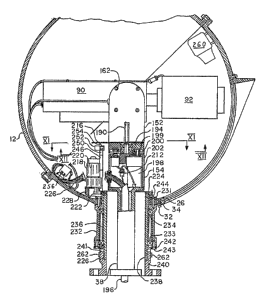
Turniny now to the power operated embodiment
of the invention illustrated in Figures 3 and 6 of the
drawings, there are shown power means for tilting the
camera abou~ a horizontal axis and further power means
for panning the camera about a vertical axis which
extends through -the longitudinal centre of the innex
post 38. As shown in Figure 3, the inner post 38 is
hollow and through it extends the electrical cable to
operate the various motors and control systems for the
unit and camera. A similar hollow post can also be
used in the manual embodiment described above. The
firs-t power means, indicated generally by the
referenca 150 is mounted on a bracket member 152, the
construction of which can be seen clearly from Figure
14. This bracket member is connected to and is
rotatable by the further power means indicated
generally bv reference 154. The ~wo power means are
constructed in a very similar fashion as will be
apparent ~rom the drawings and accordingly the
detailed description will be directed primarily to the
~; construction of the first mentioned power means shown
- in Figure 6 and Figure 14 ~nd those features of the
power means 154 that differ from the power means 150.
The power means for tilting includes an electrical
drive gear motor 158, a small driving gear 159 and a
larger gear 161 having internal teeth. The gear motor
158 i5 mounted inside a motor housing or stator 156
:'
that is connected to ~he bracket 152 by means of bolts
,
5~
- 21
or studs 162. Four holes 164 are provided in the
bracket 152 to accommodate these bolts. An integral
centre shaft 166 extends from the closed end of the
stator 156 and on this shaft a rotor 160 is rotatably
mounted. Two se~s of ballbearings 168 and 169 are
provided to mount the rotor. The bearings 168 are
held in place on the shaft by means of a retaining
ring 170. The hole 172 in the rotor has a reduced
width in its centre formed by a rib 174. This rib
keeps the two ballbearings a suitable distance apart.
A step 175 is formed at the bottom of the shaft to
hold the bearing 169 in place. Connected to one side
of the rotor 160 is a smaller L-shaped bracket 176
that forms part of the camera support mechanism for
the camera 90. Standard bolts 177 extend th.rough four
holes 178 in the bracket and into threaded holes 180
in the rotor in order to attach the bracket. In order
to make the bracket 176 quite rigid, it can have two
~: lip braces 182 welded thereto. The bracket 176 has
holes 183 therein for passage of bolts 184
therethrough. These bolts connect a camera support 86
of the same type as is illustrated in Figure 7.
. Returning to the construction of the large
bracket member 152, this member includes a horizontal
section 153 having four bolt holes 155 therein, a
~:
,
~:; ~.,
,
.
.
~: - , ,: . ... . .
~r~
- 22
sloping sect.ion 157 and a vertical section 186. In
order to make th.is bracket very rig.id, .it is provlded
with a two lip braces 188~ It can also have a central
r:ib or brace 190 extending downwardly from ~he sloping
sect.i~n 157. Four bolts 192 attach the bracket to a
rotor 194 of the power means 154.
The construction of the power means for
panning the camera support mechanism about a vertical
axis indicated at 196 includes an electr.ical drive
gear motor 198, a dr.iving gear 199, and a larger
driven gear 200 with internal teeth. The construction
;~ and engagement of these gears can be seen clearly from
`~ Figure 12. The motor 198 is mounted inside a motor
~ housing or stator 202 that is detachably mounted by
: 15 bolts (not shown) to the top of the inner post 38. It
w.ill thus be seen that the stator 202 with its
vertical shaft 204 and the rotor 194 provides means
for mount.ing the camera support mechanism for rotation
about the selected vertical axis at 195.
Both the power means for tilting the camera
and the power means for panning the camera are
~;~ optionally provided with potent.iometer controls so
that the unit can be programmed to rotate or tilt the
camera to one or a number of preselected pos.itions.
The potentiometer for tilt control is shown at 206
~.
-.
; . . .
;~.. ..
: '
. . :: . -
in Figure 6a and this potentiometer is connected by a
shaft to a gear 208 that engages the large internal
gear 161. Such control mechanisms are well known in
the control art and it is deemed unnecessary to
describe its construction in any further detail
herein. The potentiometer control for the scan
function is shown in ~igure 3. This potentiometer is
connected by a shaft to a gear 211 (see Figure 12)
where it engages the large internal year 200. A plug
and socket connection 212 for the potentiometer and
the electric motor 198 is connected to the inside of
the stator 202.
Mounted on top of the rotor 194 is a cam plate
214, the function of which is described hereinafter.
This plate, which has the same diameter as the rotor,
has holes 215 therein for passage of the bolts 192.
The plate has a radially outwardly extending finger
216 for triggering microswitches.
Because of the need to mechanically isolate
the camera and the camera mount from the enclosure 12,
separate power means are provided for rotating the
enclosure about the same vertical axis as that around
which the camera rotates. In addition, there are
control means for operating this separate power means
in order to maintain the window 22 in front of the
; lens 92. The separate power means for rotating the
: ":,
`::
.:- .:.,,
.. : , -: :
. .: , . .
'
- 24
the enclosure is indicated generally at 218 and this
power means includes an electric gear drive motor 220,
a small driving gear 222 and a large spur gear 224
that is rigidly moun-ted at the top end of the
sleevelike support 226. The mounting arrangement for
the electric motor 220 is shown in Figures 3, 9, and
10. The motor is mounted on top o a "C" shaped
support member 228 that has a suitable opening for
passage of the drive shaft of the motor and to
accommodate the gear 222. The member 228 is partially
cut away at 230 to accommodate the edge of the spur
.. gear 224 and to permit engagement between it and the
driving gear 222. The support member 228 can be
~ welded to a metal ring 231 that forms part of the
;~ 15 rotatable mounting for the enclosure. Bolts extend
through slots in the member 228 and into threaded
:. holes 229 to connect the motor to the top of the
member ~28.
~ The enclosure 12 shown in Figure 3 is
:~ 20 rotatably mounted on the support 226 which has
arranged thereon a rotatable, open-ended cylinder 232.
Inside this cylinder are two sets of ball bearings 233
: and 234 separated by spacers 236. An internal
open-ended cylinder 238 forms an upper section of the
support 226 and is slidably received inside a bottom
section 240 having a generally L-shaped cross-section.
- ~ Set screws 241 can be used to tightly hold the member
. 238 in the bottom section 240. A mounting ring 242
~ .
. - ~ -- . .... ,.. ,, .. ;.. -.. , : ..
- . : : . : : .
:. , .
: : -:
: . :
~V~6~
- 25
is attached by screws 243 to the bottom end of the
cylinder 232 in order to hold the bearing 233 in
place. The top end of the cylinder 232 is rigidly
clamped to the bottom of the enclosure by means of the
aforementioned metal ring Z30 and suitable bolts 244
that pass through the holes 40 in the enclosure. It
will thus be seen that because the motor 220 is
mounted on the rotatable ring 230 and the spur gear
224 is fixed against rotation, rota~ion of the small
gear 222 by the motor will result in rotation of the
spherical enclosure. In addition, as will be clear
hereinafter, any movement of or vibration of the
enclosure will not be transmitted to or affect the
camera and its lens.
The control mechanism for operating the motor
220 is mounted on a curved metal, preferably
aIuminium, bracket 252 which is mounted on the ring
231 by two spacers 246 each having a threaded, ~xi~lly
extending hole at the top end and a threaded male
connector at the bottom end. The bracket 252 is
attached to each spacer 246 by a screw 250. Two
microswitches 254 are mounted on the bracket 252. On
top of each microswitch is an actuator that is located
for contact with the finger 216 on the cam plate. The
operation of ~lis control means will be described
~,
~`
~ '
:
~3L.26~S~
- 26
further hereinafter with reference to the circuit
diagram.
Also located inside the enclosure 12 of Figure
3 is an assembly rail 256 having a number of
electrical terminals for attachment of the various
wires that operate the camera, the lens, and the
motors described above. Preferably the assembly rail
is attached by screws or bolts to the enclosure.
Another optional but preferred feature is a
combination blower and heater 260 arranged above the
window 22. The heater/blower 260 can be operated
whenever required in order to maintain the window
clear and free from frost. It can be of any standard
construction and therefore a detailed description
thereof is deemed unnecessary. In the illustrated
embodiment it is attached to the lower section of the
spherical enclosure by any suitable means such as
bolts (not shown).
In order to prevent ice build-up around the
20: bottom end of the cylinder 232, which build-up might
prevent the enclosure from rotating, standard blanket
heaters 262 may be placed around the circumference of
~ : ; ~ , ,:.. .,.-. - : :
., , ~ . : :
. .
- 27
the bottom section 240 of the support. As with the
other blankat hea~ers, these heaters can be attached
by adhesive to the metal section 240.
Figures 17 to 19 illustrate the electrical
circuits that can be used to operate the surveillance
camera systems described above. The illustrated
circuits are all located within the enclosure 12. The
electrical terminals illustrated at the bottom of
Figures 17 to l9 are located at the assembly rail 256
shown in Figure 3. These terminals are connected by a
bundle of wires or a cable 266 to a standard receiver
(not shown) located outside the housing. The receiver
is of well known construction and does no~ form part
of the present invention. It is hard wired to an
operating terminal for the camera unit. The receiver
can be similar to that sold by Pelco Sales, Inc. of
Fresno, California, for lts surveillance camerasO The
preferred re`ceiver is deslgned to operate a 12 volt
D.C. system.
In Figure 17 the reference letter P indicates
~ a plug while the reference letter J indicates a jack.
;- ~ The five electrical lines 267 to 271 are standard
lines for the operation of a teIevision camera. As
;` ~ thetelevision or surveillance camera is of well known
`'~ 25 construction, as i: its operation, a detailed
~ description thereof herein is deemed unnecessary. The
:.
; ;:
:
- 28
lines 272 and 273 extending from jack J2 operate the
heater 104 for the spherical enclosure. In the line
272 there is a thermostat 274 which can be the type
made by Klixon and bearing part number
20640L58318-50L80-lW29V. The thermostat will operate
the heater 104 whenever the temperature in the
enclosure falls to 10 degrees Celsius or less. The
heater itself can comprise a number of blanket heaters
such as those made by Benchmark and bearing part
number BF1031 115V 40W. In one preferred embodiment
of applicant's unit there are six such blanket
heaters.
Electrical lines 276 and 277 extending from
the jack J3 operate the blower and heater unit 260
which preferably is a 115 volt, 250 watt unit. The
blower and heater are simply operated from a remote
switch, being turned on whenever required by the
operator.
Electrical lines 280 and 281 extending from
jack J4 operate the exhaust fan motor 144. The
operation of this motor is controlled by a thermostat
282 which operates the mot.or when the temperature in
the spherical enclosure exceeds 28 degrees Celsius.
The thermostat can be the type sold by Klixon under
part number 2064F58148-50F901.OR84V.
~;:
. . .:
: :
.. ~
~L~6~
2g
The illustrated auxillary circuit is optional
and it could, for example, operate a windshield wiper
for the window 22 if desired.
The circuits and components in the dashed
outline at 284 operate and control the motor 198 which
is able to pan the camera. Because the motor is a
; D.C. motor, it is simply necessary to change the
voltage of the current through the motor in order to
change the speed thereof. Also, by changing the
polarity, the direction of rotation can be changed.
Standard one direction diodes in the circuit are
indicated by references CRl and CR2. A capacitor Cl
which in one preferred embodiment has a capacity o~
0.1 microfarad is connected in the motor circuit and
acts as a filter. If switch Sl is closed the current
in line 285 will flow through the switch and through
the dlode CR2 to the motor. At this time the current
cannot flow through the switch S2 which isjopen nor
can it pass through the diode CRl because of its
direction. This will result in the motor 198 (MB)
turning in a certain direction, say clockwiseO
However, if the controls are operated to close switch
S2 and open switch Sl and reverse the direction of the
current, the current will then flow through line 287,
through the motor, through switch S2 and through the
~:
,
:
: j: ` :
' " -
-
:~
~x~
-- 30
diode CRl. This will cause the motor to turn in the
opposite direction, that is, counter-clockwise. The
capacitor C10 is a standard filter device provided to
pro-tect the circuit from RF noise.
The three electrical lines 288, 289 and 290,
resistors Rl and R2 and the potentiometer R3 are
optional and are only required in order to programme
the panning operation. In other words, with this
additional circuit it is possible to use a known
memory control system and to programme it so that the
camera will pan to certain desired positions. The
potentiometer R3 is shown in Figure 9 and in a
preferred embodiment it is a ten turn unit of 5K ohms
capacity. The resistors are provided to balance the
circuit only and the use thereof is well known in the
control system art.
The electrical circuit for controlling the
~; rotation of the dome or spherical enclosure is
outlined at 292. It will be noted that this circuit
has the same power source as the panning motor 198
because lines 293 and 294 as well as line 295 are
connected directly to corresponding lines in the
; circuit for the motor 198. As a result of this
arrangement, the camera enclosure will always rotate
in the same direction about the ver~ical axis as the
camera. The motor 220 can be that sold by Brevel
bearing part number 713-982924-702 15 84.
:~
,
' ' ''' :
' , ' ' ,
"' ~
~686~
- 31
The switches S3 and S4 are normally closed.
These switches S3 and S4 are the two microsw.itches 254
which are actuated by the finger 216 on the cam
plate.
One of the switches, say S3, can be operated
by the f.inger of the cam plate when rotating .in a
clockwise d.ixect.ion and ~he other switch, say S4, is
operated when rotating in the coun~er-clockw.ise
d.irection.
When the l.ines 285 and 287 are energized then
both the camera and the dome enclosure will start to
rotate in the same direction but the dome enclosure is
des.igned to rotate at a greater speed than the camera.
This will cause the finger 216 on the cam plate to
eventually actuate either switch S3 or S4 depending on
d.irection, and opening the switch, and break line 293.
The current will then pass through the resistor R4
~' slowing the rotation of the dome dr.ive motor 220. The
dome enclosure will now rotate at a slower speed than
the camera until the finger on the cam releases S3 or
S4 aga.in closing the circuit. This control system
ensures that the camera lens and window 12 are always
aligned. In a preferred embodiment~ the resistance R4
: is a 10 ohms resistor and the filter capacitor C9 is
: ~ 25 0~1 microfarad in size.
: The circuit and components for operating and
controll.ing the tilt motor 158 are .indicated in the
outl.ine 295. As will be seen by comparing the c.ircuit
.in outline 295 to the circu.it in outline 284, the two
- : , , :
: , ' ' :, ': . .:
,.. ... ..
; .' ' ::''
~6~6~
- 32
circuits and their components are substantially the
same and, in fact, the two circuits operate in
essentially ~he same manner. Again, the control
circuit -that includes the resistors R5 and R6 and the
potentiometer R7 is optional, depending on whether or
not it is desired to programme the camera to move to
certain preset locations. The potentiometer R7 is
indicated by reference 206 in Figure 6A. The speed of
rotation of the motor 158 will depend upon the voltage
in lines 296 and 297. By switching the polarity in
these lines, the direction of rotation of the motor
can be changed as explained above.
The group of wires indicated generally at 298
are provided to operate the camera lens which is a
standard lens of well known construction. It includes
motors for operating the iris of the lens, for
controlling the zoom function and for ocusing the
lens. As the electrical circuits for the operation of
these motors are well known, they are not been
illustrated herein. The lens and its operation forms
no part of the present invention.
In the embodiment of Figure 4 the camera
;~ mounting and camera and the spherical enclosure are
attached to a rotor 322 which is free to rotate around
a vertical shaft 325. This shaft is part of stator 314
~`~ that is detachably mounted on a pedestal 312. This
`~ embodiment is suitable for some surveillance camera
applications, particularly when use of shorter focal
-
.. ... .
, .,, ,.. ~,. .. ..
.
.
~L~6~365~
length lenses or less severe wind/ice conditions
indicate tha-t vibration would not be as severe a
proble~.. The spherical enclosure 302 and its window
304 are constructed in the same manner as the,versions
described above. The ventilating mechanism 306 at the
top of the enclosure is identical to that used in the
embodiment of Figure 5.
The stator 314 contains an electric gear drive
motor 316. The motor 316 has fixed on its shaft a
; 10 driviny gear 318 which engages a larger gear 320 with
internal teeth. The large gear is bolted to the rotor
322. Inside the rotor are two sets of bearings 323
and 324 that extend around the central shaft 325. It
will be understood that the bearings are held in place
in a manner the same as the bearings used with the
panning mechanism of the embodiments described above.
Adjustably mounted on the rotor are two cam members
326 that are fixed relative to the rotor by set screws
327. Each cam 326 is provided to limit the rotation
;` 20 of the camera enclosure. Each cam has a downwardly
~ extending step 329 that is placed in a groove 331
; formed in the top of the rotor. Two microswitches 333
are mounted on round plate 335 which is 1xed by two
bolts 337 to the top of the shaft 325. When one of
; 25 the cams 326 engages a microswitch 333, the switch 333
i8 opened and further rotation of the camera in that
; direction is prevented. The camera can then be
, ~ :
;: - : , , , - . .
, : ;' .' ~:
~ ~8~5~
- 34
rotated in the opposite direction until the other cam
326 is reached. The rotor 322 has a Elange 328 that
suppor-ts the camera enclosure. Connecting bolts 330
extend through an annular metal ring 332, through
holes in the enclosure, through the flange 328 and
into threaded holes in a skirt member 334. The skirt
member extends down to a flange extending around the
top of the pedestal 312. Located above this flange
336 in an annular space 338 is a coiled cable 340
which contains the electrical wires for operating the
camera 341, the lens 343 and the tilting motor fnot
shown). A panning bracket 342 is detachably connected
by bolts 344 to the top of the rotor. The bolts 344
extend through tubular spacers 345 shown in Figure 16.
These spacers are required to provide head room for
the cams 326. They permit the cams to be removed and
adjusted as may be required from time to time. The
bracket 342 is connec-ted to the housing for the
tilting motor in the same manner as described aboveO
It will be appreciated by those skilled in
this art that various modifications and changes can be
made to the illustrated camera housing units and
camera supports without departing from the spirit and
scope of this invention. Accordingly, all such
modifications and variations as fall within the scope
of the appended claims are intended to be part of this
invention.
:
i :, . . , . i . . -
- , . . .
,