Note: Descriptions are shown in the official language in which they were submitted.
~2~
HONEYCOMB STRUCTURE WITH BAND JOINED
FOLDED MATERIAL AND METHOD OF MAKING SAME
Background of the Invention
The present invention relates to an expandable
honeycomb structure such as used for window coverings. The
structure is made of foldable material which in the expanded
condition defines a plurality of longitudinally extending
cells, one on top of the other. In the retracted state of
the honeycomb structure, the adjacent cells are collapsed on
each other.
The prior art discloses various honeycomb
structures made from foldable material. Representative of
such prior art are the Rasmussen patents Re 30,~54, and
31,129, the patents to Suominen, Patent Nos. 4,28~,485 and
4,388,354, and the patent to Masuda, No. 3,164,507. In
addition, U.S. Patent No. 4,450,027 to Colson discloses a
honeycomb structure constructed from foldable material which
is folded longitudinally of the material and wound onto a
rack in overlying layers. The layers are adhered together to
form the cells of the honeycomb structure. The present
invention is most directly a variation of the honeycomb
structure and method of making it as disclosed in the '027
patent.
~5
In constructing honeycomb structures from a single
length of material in accordance with the teachings of the
'027 patent, the opposite longitudinal edges of the length ~f
material are progressively folded over one side of the
material. Adhesive is then applied to the exposed
longitudinal edges whereby they adhere to the overlying lay~r
of folded material as it is wound onto the rack. With the
single folded construction of the '027 patent, the
application of the adhesive must be carefully controlled so
as not to interfere with the processing operation and in
- `.
,: - ''
~;~68~
--2--
particular, the stacking operation. Also, the choice of
adhesive used must be carefully chosen to be compatible with
the material from which the honeycomb structure is being
formed. rmproper choice and application of adhesive can
produce an unacceptable productO
Where the honeycomb structure is to be used for
window coverings or panels, it is often desirabl to
fabricate the honeycomb structure from somewhat porous
material. This is desirable to give, for example, a
translucent effect to the honeycomb structure when, in its
expanded condition, covering a window. With porous material,
there is an increased tendency for any adhesive to bleed
through the material. This in turn, can result in the
opposite walls of the individual cells becoming adhered
together as they are wound onto the rack in overlapping
layers. Examples of suitable materials are non-woven fibers
of polyester, woven material from plastic or textile fibers
plus plastic. Also, laminates can be used. With these
materials, it will be the absorbtion in and through a
somewhat porous layer that creates the bleeding through
problem. When this results, the product is either unusable
or the cells must be carefully pulled to their expanded
condition before the adhesive has fully set. This sometimes
is not possible or feasible, and, in any event, it increases
the manufacturing costs.
In addition to manufacturing problems which can
result from improper application of the adhesive, the choice
of adhesive can also result in an unsuitable product.
Honeycomb structures as used for window openings are, in many
situations, subjected to continuous and severe sun
conditions. These conditions can have an adverse affect on
the adhesive causing separation of the adjacent cells.
Obviously, this is undesirable. Although suitable adhesives
~,
.- ,
' ~
~26~3fi9~
--3--
to prevent this are available7 they may be incompatible with
the manufacturing process as discussed above.
Another aspect of the honeycomb structures of the
prior art relates to the creasing or pleating of the material
along fold lines to form each cell. One reason pleating is
provided is to assist in the orderly collapsing of the
individual cells as the structure is moved between an
expanded and a retracted position. Without pleats, the
collapsing of the cells would tend to be haphazard and not
give a neat appearance to the structure.
In the cell construction disclosed in the '027
patent, the pleats are formed to be permanent so that the
faces of the honeycomb structure extend in an angular
configuration in the expanded condition of the structure. If
the pleats are not carefully and properly formed, they will
tend to hang out. This is especially so after long,
continued use of the structure with the expanded condition
being one where the cells lie one below the other. In such
an orientation, the weight of the structure itsel~ pulls on
the material of the overlying cells with the greatest forces
being exerted at the top of the structure by the entire
weight of the underlying cells. Any falling out of the
pleats tends to increase the overall height of the structure
over the height as initially manufacturad. The effect of
this can be unpleasing and unsatisfactory, both aesthetically
and physically.
Summary of the Invention
According to the teachings of the present
invention, an expandable-collapsible honeycomb structure is
provided from a length o~ material haviny its opposite
longitudinal edges folded over on one side of the material
. .
: ,~
- .: - .
. . .
-. - ~..
: : :: ..
s
--4--
and secured to a second separate strip of material. The
strip of material also functions to connect each cell of khe
honeycomb structure to the adjacent overlying cell. With
different material being used to complete each cell and
connect them to the adjacent cells, the problems encountered
with adhesives of the prior art can be avoided. In
particular, the strip material can be of different physical
characteristics than the material from which the rest of the
honeycomb structure is formed. Also, the choice of adhesives
can be widened. Thus, bleeding of the adhesive through the
material and the attending manufacturing problems can be
avoided. Also, adhesives which are less susceptible for
deterioration from extreme sunlight can be used.
With applicant's invention, it is also possible to
adjust the folding of the longitudinal edges of the material;
and the second strip material can thus be secured to these
edges at a location offset from the center of material. With
appropriate pleating on the opposite faces of the honeycomb
structure, one side of the structure can be made to hang
straight in the expanded condition of the structure,
resulting in no tendency of the pleats on the other side of
the structure to fall out during extended use.
In accordance with the method of forming the
honeycomb structure of the present invention, a first
continuous length of material is fed along its length and its
opposite longitudinal edges are folded over one side of the
material. This folded material is then aligned with a second
material in strip form which is fed into overlying relation
with the one side of the folded material. These aligned
materials are then wound into a continuous loop to form
layers of folded and strip material. These layers are
adhered together by connecting the strip material to the
facing surface of the next layer of material. At the same
,,. ~, :
.
- `
: : " ,
... ,,.,.,.,.,.~.,,., .. ~. . ~ ..
~63~
--5--
time or preceding this connection of the adjacent layers, the
strip material is itself connected to the folded longitudinal
edges of the folded material. The connected layers form the
indivuidual cells of the honeycomb structure when the lo~p is
cut into a finite length.
With applicant's invention, the material is
advantageously creased along fold lines during the folding
process. These folds can be creased to the extent necessary
to permit an orderly collapsing of the cells and they can
also be made permanent to the extent that they prohibit
falling out of the creases in the expanded condition of the
honeycomb structure. Where the structure is to be used as a
window covering and the pleated appearance is to be provided
on only one side of the honeycomb structure, the folding of
the material is such that the material of the other side of
the structure will fall out in a straight plane in the normal
expanded condition of the structure.
Brief Description of the Drawings
FIG. l is a perspective view of the honeycomb
structure in its expanded condition and fabricated according
to the teachings of the present invention;
FIG. 2 is a cross-sectional view of a number of
adjacent cells of the honeycomb structure shown in FIG. l;
FIG. 3 is a cross-sectional view of a number of
cells of a modified embodiment of the honeycomb structure
shown in FIGS. l and 2;
FIG. 4 is a plan view of a suitable apparatus for
fabricating the honeycomb structure according to the
teachings of the present invention;
.
, ~
: ;
~%6~6~i
~j
FIG~ 5 is a cross-sectional view taken along lines
5-5 of FIG. 4;
FIG. 6 is a cross-sectional view taken along lines
6-6 of FIG. 4; and
FIG. 7 is a cross-sectional view similar to FIG. 6
showing a modified embodiment of the folded construction of
the cell material.
Detailed Description of the Preferred Embodiments
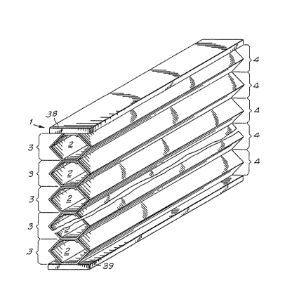
As shown in FIGS. l and 2, the expandable honeycomb
structure of the present invention generally designated by
reference number l, is constructed of a plurality of
longitudinally extending cells ~. Each cell has a
longitudinally extending front face 3 and a longitudinally
extending back face 4. For the purpose of easy
identification, the faces 3 are referred to as front faces,
and the faces 4 as back faces. "Front" and "back" hold no
limitation as to the position of the structure, for example,
when used as window coverings in building constructions.
Also, "honeycombn is used in the broad sense to mean
connected cells, not necessarily hexogonal, as described and
shown herein. Each cell is constructed of a foldable
material 5 folded along longitudinally extending fold lines 6
and 7 and having its opposite longitudinally ext~nding edges
8 and 9 secured to a second length of material lO. This
length of material is in strip form and separate from the
foldable material. It extends longitudinally between the
cells in their completed condition and connects adjacent
cells together. More particularly, the longitudinal edges ll
and 12 of the strip material are connected to the
longitudinal edges 8 and 9, respectively, of the folded
~material and the central longitudinally extending portion 13
-7-
of the strip material is connected to the foldable material
of the overlying cell structure.
In the construction shown in FIGS. l and 2, the
opposite longitudinal edges 8 and 9 of the foldable material
5 are spaced from each other by a distance w. The central
section 13 of the strip material lO is thus exposed across
this width w and connected to the overlying cell across this
same distance. This attachment of the adjacent cells spaces
the front face of each cell from the back face 4 by the
distance w. In the construction shown in FIGS. l and 2, the
connection of the cells across the distance w is located
centrally of the honeycomb structure to produce a symmetrical
construction.
In the construction shown in FIG. 3, the connection
of the adjacent cells is laterally offset from the center of
the honeycomb structure. Thus, the front face of each cell
has a greater amount of material extending between adjacent
cells than the back face thereof. By controlling this offset
and the amount of creasing along the fold lines 6', 7', back
face 4' of each cell can be made so that the folds 7' hang
out in the normal expended condition of the structure. With
this, no further expansion of the cells is possible. Thus,
the pleated configuration on the front face 3' of each cell
has no further tendency to pull out. To attain this
construction, the creasing along fold line 7' is made
sufficient to assist in the normal orderly collapsing of the
cell, but is not of sufficient strength to prevent falling
out in the expanded condition of the structure. The crease
along the fold line 6', however, is made permanent where the
sharp angular configuration is desired.
In accordance with the method of manufacture of the
honeycomb structure, the apparatus of U.S. Patent No.
, . -
- - :'''' .
,. :
.~ - .
;9~
4,450,027, suitably modified, is used.
FIG. 4 of the present application is a plan view of
the apparatus of the '027 patent as modified in accordance
with the teachings of the present invention. As shown in
FIG. 4, a supply of foldable material S is provided by a roll
14 of the material. The material may be a thin film of
polyester plastic or Mylar*or any other material, suoh as
those previously mentioned, h~ving similar or suitable
characteristics for honeycomb structures. From the supply
roll 14, the length o~ material is directed around the guide
roller 15 and through the alignment block 16. The material
is then creased by passing it through a creaser assembly 17.
This creaser assembly, as shown in FIG. 5, includes a backing
roller 18 and cooperating creaser wheels 19. These wheels
have sharp peripheral surfaces; and as a length o~ material 5
passes between the backing roller and creaser wheels, a pair
of creases 6 and 7 are formed in the material on one side
thereof. These creases define fold lines of demarcation
between the opposite longitudinal edges 8 and 9 of the
material and the central section thereof.
From the creaser assembly 17, the material passes
around two folding rollers 29, 21. As with the apparatus of
the '027 patent, these folding rollers are offset from a
straight line between the creaser roller 19 and a folding
mechanism 22. These folding rollers, tog~ther with the
folding ~echanism 22 fold the l~ngth of material 5
longitudinally along the crease lines 6 and 7. The folding
; is such as to fold both longitudinaly edges 8 and 9 over the
one side of the length o~ ~aterial. This folding is done
progressively as the length of material is fed through the
apparatus. The ~olded condition of the len~th of material as
*Trademark
~ ,~
.: ' ~ ; ~, ' '
~L2g~ 5
g
it exits from the folding mechanism 22 is shown in FIG. 6.
As there seen, the folding leaves the longitudinal edges
spaced from each other.
After folding of the material, it is directed
through a crimper assembly 23 which is comprised of facing
crimp rollers 24 and 25. These rollers are aligned with each
other and overlie one or both of the fold lines 6 and 7 to
tightly press and squeeze the material so as to form a
permanent folds along either or both of these lines.
Depending on the nature of the material, this crimper may or
may not be necessaryO Where the material has the
characteristics of the polyester film material disclosed in
the '027 patent, the crimper assembly 23 would be utilized.
Also with such material, the fold can be assured of being
permanently set by further passiny the folded material around
the peripheral surface of the roller 26 which is heated.
This roller and the cooperating press rollers 27 and 2~ apply
rolling pressure across the entire width of the material to
set the crimps permanently at a sharp angle. Again, the
roller structure 27 and 28 need not be included where the
material does not require its use. Further, other structures
may be used, provided that the fold lines 6 and 7 are
properly set to maintain the angular configuration shown in
FIG. l. Also, in some situations, it may not be desirable to
have permanent fold lines in both or either of the faces of
the final honeycomb structure. Instead, it may be desirable
to have fold lines which only aid in assuring that the cells
collapse in an orderly fashion.
After folding of the length of material, it is
directed around suitable guide rollers 29, 30, 31 as more
~ully described in the '027 patent. As the material passes
between the guide rollers 30 and 31, the strip of material lO
is progressively fed in the same direction as the foldable
~ :; ' '''
,~.
.. ..
....... .. . . .
.
.. ~ :
'
.
; : .
--10--
material and into overlying relation therewith. More
specifically, it is fed into overlying relationship with
respect to the side of the material 5 over which the
longitudinal edges 8 and 9 have been folded~ Prior to
effecting this overlying relation, the side of the strip
material lO facing away from the folded materials 5 is coated
with adhesive 33. This is done by passing the strip material
between a pair of rollers 34, 35. Roller 35 is suppli~d with
the adhesive from a source 36.
In the embodiment of the honeycomb structure shown
in FIGS. l and 2, the edges of the strip material are adhered
to the inside surfaces above the folded longitudinal edges 8
and 9. In order to do this, the strip material lO must be
fed into overlapping alignment with these longitudinal edges
and located between tham and the side of the material over
which they have been folded. For this purpose, an aligning
mechanism 37 is provided. This mechanism may be of any
suitable construction to open or maintain the folded edges 8
and 9 of the foldable material in open condition so as to
receive the strip material lO and align it properly.
Alternatively, the strip material can be fed into overlapping
relation with the foldable material at other points along the
path of movement of the foldable material through the
apparatus.
After the foldable material 5 and the strip
material lO have been aligned in overlying relationship, both
materials are fed around the roller 31 and into a stacking
area. There they are wound on a stacking arm 37 and into a
continuous loop with successive portions of the materials
overlying preceding portions. This forms a plurality of
stacked layers of folded and strip material on the stacking
arm. During the stacking operation, the adhesive 33 on the
strip material is pressed into engagement with the facing
,
'
. ' ;'
' ~
~çi8695
side of the folded material of the layer overlying it. This
adheres the exposed section 13 of the strip material to the
overlying layer to form a unitary stack of closed expandable
cells.
~ fter the desired amount of folded material is
stacked on the stacking arm 37, the length is severed from
the supply cuming from guide roller 31 and the layers of the
loop are severed to form a unitary stack of cells of finite
length as shown in FIG. 1. Alternatively, the layers of the
loop can be cut into a number of unitary stacks of cells of
finite ]ength. The honeycomb structure is completed by the
head and bottom rail structures 38 and 39.
Where it is desired to produce the structure shown
in FIG. 3, the folding of the opposite edges of the length of
material is adjusted by folding them over onto the center
section of the length by different width distances. With
reference to FIG. 7, the longitudinal edge of 8/ of the
length of material is folded along the fold line 6' to a
width greater than the folding of the longitudinal edge 9'
along the fold line 7~O FIG. 5 shows in dotted lines the
adjustment required of the creaser wheels 19 for this
purpose. The connection of the strip material 10 to these
laterally offset edges 8' and 9' will result in the
construction of FIG. 3 and the front face 3' of each cell
will have more material extending between adjacent cells than
the back face thereof. Thus, if no more than a minimal or no
crease is effected along the fold line 7', this fold will
hang out when the cells are expanded and the other face of
the honeycomb structure will have pleats which will not fall
out over a period of extended use. Effectively, to produce
this result, the longitudinal edge 9' is folded over the
crease or fold line 7' by a distance equal to half the
distance any one cell extends between its adjacent cslls in
.
.
. .
.
- .,: .
~: : "" `' ~ .: . ' '
.~ :
. .
.
:.., ~ ~
the normal expanded condition of the honeycomb structure.
This distance can be easily controlled to accurately produce
a structure with a precise height in its expanded condition.
: 30
.
, . . .
,.