Language selection

Search

Patent 1268956 Summary

Third-party information liability

Some of the information on this Web page has been provided by external sources. The Government of Canada is not responsible for the accuracy, reliability or currency of the information supplied by external sources. Users wishing to rely upon this information should consult directly with the source of the information. Content provided by external sources is not subject to official languages, privacy and accessibility requirements.

Claims and Abstract availability

Any discrepancies in the text and image of the Claims and Abstract are due to differing posting times. Text of the Claims and Abstract are posted:

  • At the time the application is open to public inspection;
  • At the time of issue of the patent (grant).
(12) Patent: (11) CA 1268956
(21) Application Number: 500888
(54) English Title: ROOFING ELEMENT
(54) French Title: ELEMENTS DE COUVERTURE
Status: Deemed expired
Bibliographic Data
(52) Canadian Patent Classification (CPC):
  • 72/53
(51) International Patent Classification (IPC):
  • E04D 1/00 (2006.01)
  • E04D 1/04 (2006.01)
(72) Inventors :
  • MIKO, HANS-JURGEN (Austria)
(73) Owners :
  • ETERNIT-WERKE LUDWIG HATSCHEK AKTIENGESELLSCHAFT (Austria)
(71) Applicants :
(74) Agent: SWABEY OGILVY RENAULT
(74) Associate agent:
(45) Issued: 1990-05-15
(22) Filed Date: 1986-01-31
Availability of licence: N/A
(25) Language of filing: English

Patent Cooperation Treaty (PCT): No

(30) Application Priority Data:
Application No. Country/Territory Date
A 415/85 Austria 1985-02-13

Abstracts

English Abstract


ABSTRACT OF THE DISCLOSURE


The invention relates to a roofing element, in particular
a concrete roofing panel, at whose underside extend a suspension
ledge and a base rib, while at least two cross ribs of lesser
thickness than the base rib extend in the covering or over-
lapping region next to the base rib and parallel thereto, with
the basic surface of the base rib extending parallel in relation
to the outer surface of the roofing element.For increasing the
tightness of the roofing element, the thickness of the roofing
element of optionally S-shaped or wave-shaped cross section in
the apex of the cross rib farthest removed from the base rib is
slightly, up to 6 percent at the most, less than the thickness
of the roofing element in the base rib and the height of further
cross ribs disposed between the base rib and the cross rib
farthest removed from the base rib is less than the height of
the cross rib farthest removed from the base rib.


Claims

Note: Claims are shown in the official language in which they were submitted.


The embodiments of the invention in which an exclusive
property or privilege is claimed are defined as follows:
1. A roofing element, in particular a concrete
roofing panel, at whose underside extend a suspension ledge
and a base rib, while at least two cross ribs of lesser
thickness than the base rib extend downwards in the covering
or overlapping region next to the base rib and parallel
thereto, in which covering region the roofing element in
the installed state overlaps an underlying identical roofing
element with the basic surface of the base rib extending
parallel in relation to the outer surface of the roofing
element, comprising that for increasing the tightness of
the roofing element, the thickness of the roofing element
in the crest (apex) of the cross rib farthest removed from
the base rib is slightly, up to 6 percent at the most, less
than the thickness of the roofing element in the base rib
and that the height of further cross ribs disposed between
the base rib and the cross rib farthest removed from the
rib is less than the height of the cross rib farthest
removed from the base rib.

2. The roofing element according to claim 1, wherein
the thickness of the roofing element in the crest (apex)
of the further cross ribs disposed between the base rib and
the cross rib farthest removed from the base rib is about 8
to 16 percent less than the thickness of the roofing element
at the base rib.

3. The roofing element according to claim 1, wherein
the thickness of the roofing element above the groove,
bottom of the grooves between the base rib and the further
cross ribs and between these and the cross rib farthest
removed from the base rib is equal.


-5-

4. The roofing element according to claim 1, wherein
the roofing element is made of concrete.


5. The roofing element according to claim 1, wherein
the roofing element is of S-shaped or wave-shaped cross
section.


6. The roofing element according to claim 1, wherein
the thickness of the roofing element in the crest (apex)
of the further cross ribs disposed between the base rib
and the cross rib farthest removed from the base rib is 10
to 12 percent less than the thickness of the roofing element
at the base rib.


7. In a roofing element having a suspension ledge and
an overlapping section opposite the suspension ledge for
overlapping an adjacent roofing element, the improvement
comprising:
a base rib extending a prescribed length from the
overlapping section toward the adjacent roofing
element for contacting the adjacent roofing
element;
a first cross rib disposed between the base rib
and the suspension ledge and extending a prescribed
length from the overlapping section toward the
adjacent roofing element; and
a second cross rib disposed between the first cross rib
and the suspension ledge and extending a prescribed
length from the overlapping section toward the
adjacent roofing element, the length of the second
cross rib being greater than the length of the
first cross rib, and the length of the second cross
rib being less than the length of the base rib by
up to approximately 6 percent of the length of the
base rib.


-6-


8. The improvement according to claim 7, wherein
the length of the first rib is less than the length of the
base rib by a range from approximately 8 percent to
approximately 16 percent of the length of the base rib.


9. In a roofing element ahving a suspension ledge and
an overlapping section opposite the suspension ledge for
overlapping an adjacent roofing element, the improvement
comprising:
a base rib extending a prescribed length from
the overlapping section toward the adjacent
roofing element for contacting the adjacent roofing
element;
a first cross rib disposed between the base rib and
the suspension ledge and extending a prescribed
length from the overlapping section toward the
adjacent roofing element, the length of the first
cross rib being less than the length of the base rib
by a range from approximately 8 percent to approxi-
mately 16 percent of the length of the base rib;
and
a secondcross rib disposed between the first cross rib
and the suspension ledge and extending a proscribed
length from the overlapping section toward the
adjacent roofing element, the length of the second
cross rib being less than the length of the base
rib by up to approximately 6 percent of the length
of the base rib.


-7-

Description

Note: Descriptions are shown in the official language in which they were submitted.


~ 3~35~j

The invention relates to a roofing element9 in particular a
concrete roofing panel, at whose underside extend a suspension ledge
and a base rib, while at least two cross ribs of lesser th;ckness
than the base rib extend in the covering or overlapping region next
to the base rib and parallel thereto, while the basic surface of the
base rib extends parallel in relation to the outer surface of the
roofing element.
Roofing elements of this type are known, for instance, from AT-PS
278321.The sealing behavior and the support of such roofing elements
on a roofing element disposed underneath is not optimal, however, and
moisture and wind can penetrate.
It is the object of the invention to form roofing elements of this
type in such a manner that they assure the tightest possible sealing
against penetrating moisture and drafts in the finished roof.
According to the invention, this ;s achieved in a roofing element of
the type initially mentioned by providing, so as to increase the tight-
ness of the roofing element, for the thickness of the roofing element
of optionally S- or wave-shaped cross section, to be slightly less, up
to 6 percent at the most, in the apex of the cross rib farthest removed
from the base rib than the thickness of the roofing element in the base
rib, and by providing for further cross ribs disposed between the base
rib and the cross rib farthest removed from the base rib to be of
lesser height than the cross rib Farthest removed from the base rib.
The cross rib farthest removed from the base rib, which is only slightly
shorter than the base rib, prevents any riding up, but at the same time
creates a space between itself and the~base rib which is available
as a sw1rl chamber for penetrating air streams, s~ that penetrating
air streams are calmed down and penetrating moisture can run off
without being influenced hy capillarity due to the inclination of

--2--


,


the roof on the respective lower or overlapped roofing element.
The pressure of the penetrating air is reduced and a contro11ed
pressure compensation between the swirl chamber and the interior
of the roof or the space below the roofing is possible. The forming
of the further cross rib(s) with lesser height than the cross rib
farthest removed from the base rib improves the effect of the swirl
chamber and thus the sealing effect between the roofing elements in
the overlapping region. Preferred is a thickness of the roofing
element in the apex of the further cross ribs disposed between the
base rib and the cross rib farthest removed from it of about 8 to
16 percent, preferably about 10 to 12 percent, less than the thick-
ness of the roofing elernent at the base rib.
The f10wing conditions are further improved in respect of sealing
and minimization of drafts penetrating into the ;nterior of the roof
if the thickness of the roofing element above the bottom of the
grooves between the base rib and the further cross ribs and between
these and the cross rib farthest removed from the base rib is equal.
The overa~ result is a roofing element of optimal sealing effect
which is simple to produce and stable.
The invention is explained by means of an exemplary embodiment
under~reference to the acco~panying drawing.
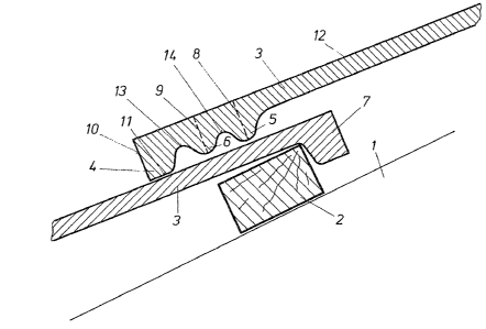
The drawing shows two roofing elements 3 in the overlapping region
in section. In the present case, the roofing elements are of S-shape
:
or wave-shape in cross section (vertical to the drawing plane). On a roof
1, there is a lattice 2 onto which the roofing elements 3 are hoDked
by means of a suspension ledge 7, so~that roofing elements 3 wh;ch are
hooked~cnto a lattice positioned higher rest on~roofing elements 3 of a
row underneath with their overlapping or base region. The base region
of a roofing element 3 according to the invention is provided with a
'
-3-

~L~ 9 5~j


base r;b 4 having a basic surface 11 extending in sections parallel
to the longitudinal extension or the undulation parallel to the outer
surface 12 of the roofing element. Adjacent to the base rib 4, with
interposed grooves 13 and 14, is a further cross rib 6 and a cross
rib 5 farthest removed from the base rib 4.It is provided for the
thickness 8 of the roofing element 3 measured in the apex of the cross
rib 5 farthest removed from the base rib to be slightly, up to 6 per-
cent at the most, preferably 2 to 4 percent, less than the height of
the front face 10 or the thickness of the base rib 4.
The thickness 9 of the further cross rib 6 disposed between the
base rib 4 and the cross rib 5 farthest removed from the base rib 4
is about 8 to 16 percent, preferably about 10 to 12 percent, less
than the height of the front face 10 or the thickness of the base
rib 4.
The thickness of the roofing element in the bottoms of the grooves
13 and 14 is mutually equal.
The base rib 4 and the cross ribs S and 6 follow the undulation
or the S-shaped form of the roofing element and are proYided with the
features according to the invention over their entire extensions.
On principle, it is possible to provide one or more further cross
ribs outside of the cross rib 5 farthest removed from the base rib
4 in the overlapping region or to provide more than one further cross
rib 6 between the base rib 4 and the cross rib 5 farthest removed from
the base;rib 4.
The~roofing panels can have cross sections of S-shape or wave form,
they can have straight or curved sections or be provided exclusively
with straight sections or be of linear shape.

Representative Drawing
A single figure which represents the drawing illustrating the invention.
Administrative Status

For a clearer understanding of the status of the application/patent presented on this page, the site Disclaimer , as well as the definitions for Patent , Administrative Status , Maintenance Fee  and Payment History  should be consulted.

Administrative Status

Title Date
Forecasted Issue Date 1990-05-15
(22) Filed 1986-01-31
(45) Issued 1990-05-15
Deemed Expired 2000-05-15

Abandonment History

There is no abandonment history.

Payment History

Fee Type Anniversary Year Due Date Amount Paid Paid Date
Application Fee $0.00 1986-01-31
Registration of a document - section 124 $0.00 1986-04-24
Maintenance Fee - Patent - Old Act 2 1992-05-15 $100.00 1992-04-09
Maintenance Fee - Patent - Old Act 3 1993-05-17 $100.00 1993-04-02
Maintenance Fee - Patent - Old Act 4 1994-05-16 $100.00 1994-04-26
Maintenance Fee - Patent - Old Act 5 1995-05-15 $150.00 1995-04-10
Maintenance Fee - Patent - Old Act 6 1996-05-15 $150.00 1996-04-11
Maintenance Fee - Patent - Old Act 7 1997-05-15 $150.00 1997-05-05
Maintenance Fee - Patent - Old Act 8 1998-05-15 $150.00 1998-04-09
Owners on Record

Note: Records showing the ownership history in alphabetical order.

Current Owners on Record
ETERNIT-WERKE LUDWIG HATSCHEK AKTIENGESELLSCHAFT
Past Owners on Record
MIKO, HANS-JURGEN
Past Owners that do not appear in the "Owners on Record" listing will appear in other documentation within the application.
Documents

To view selected files, please enter reCAPTCHA code :


To view images, click a link in the Document Description column. To download the documents, select one or more checkboxes in the first column and then click the "Download Selected in PDF format (Zip Archive)" or the "Download Selected as Single PDF" button.

List of published and non-published patent-specific documents on the CPD .

If you have any difficulty accessing content, you can call the Client Service Centre at 1-866-997-1936 or send them an e-mail at CIPO Client Service Centre.


Document
Description 
Date
(yyyy-mm-dd) 
Number of pages   Size of Image (KB) 
Drawings 1993-09-21 1 28
Claims 1993-09-21 3 132
Abstract 1993-09-21 1 35
Cover Page 1993-09-21 1 35
Description 1993-09-21 3 144
Representative Drawing 2001-10-23 1 15
Fees 1997-05-05 1 64
Fees 1996-04-11 1 60
Fees 1995-04-10 1 59
Fees 1994-04-26 1 54
Fees 1993-04-02 1 37
Fees 1992-04-09 1 51