Note: Descriptions are shown in the official language in which they were submitted.
~2691;~5
The present invention relates generally to pneumatic rail
brake systems and more specifically to improved components for t~.e
system.
The prior art brake systems were generelly standarized to
include an ABD or eq~ivalant braking valve connected by conduits
to the brake pipe, auxuliary and emergency reservoirs and brake
cylinders. These brake valves would control all the brakes on the
trucks of a single car. If more than two trucks were to be
controlled by the brake valve, relay valves were included. These
systems include a substantial amount of conduits connecting the
elements of the brake system on each of the cars. The A~ and
equivalant brake valves include the service application, emer3ency
application, release and accelerated release function. ~ith the
development of non-conventional car designs, brake systems which
are adapations of the preexisting brake systems were developed.
These and the conventional brake systems include an unnecessary
amount of conduits per car and unnecessarily large reservoirs.
Thus, it is an object of the present disclosure to provide a
simplified fluid brake system for rail vehicles.
Another object of the present disclosureis to provide a
braking system which reduces the size of the auxiliary and
emergency reservoirs.
A further object of the present disclosureis to eliminate
unnecessary piping and reduce the number of sources of fluid
leakage.
- 2 - ~7
12691~5
Another object is to provide a group
of standard parts or modules which can be economically applied to
any type of freight car without special engineering, including
articulated cars having any number of trucks~between couplers.
Here described is a triple valve assembly
having reduced auxiliary and
emergency reservoirs mounted directly thereon. The assembly is
connected only to the brake pipe and to the brake cylinder of one
truck and controls the interconnection between the brake pipe,
brake cylinder, auxiliary reservoir and emergency reservoir to
produce charging of the reservoirs, service application and
emergency application of the brakes and release of air to the
brake cylinder. The unique triple valve, in response to the
venting of brake pipe which characterizes an emergency brake
application, provides a sequential application of pressure to the
brake cylinder. Fir~st the auxiliary reservoir pressure is
equalized with that of the brake cylinder, followed by
disconnection of the auxiliary reservoir from an application of
the emergency reservoir to the brake cylinder. This sequential
operation allows ~ncreased brake cylinder pressure while allowing
reduction in the volume of the emergency reservoir used to
accomplish this pressure.
In both service and emergency applications, a variable flow
rate valve is connected between the supply portion of tne triple
valve and the brake cylinder to allow a high flow during the
initial application of the air to the brake cylinder with a
decreased flow rate during the second stage.
, 126912S
The triple valve assembly is easily adaptable for receiving a
load responsive fixture. This fixture includes a first path for
connecting the supply to the brake cylinder and to a volume
reservoir and providing a predetermined portion of supply pressure
to the brake cylinder. ~ second path controlled by the load is
connected in parallel with the first path, and bypasses the
proportioning path and cuts off the volume reservoir for a loaded
sensed condition. A double acting piston is providea to
simultaneously open the bypass and close the dummy reservoir or
connect the dummy reservoir and close the bypass. The bypass is
also responsive to a brake released signal to bypass the
proportioning device durlng a brake release sequence.
A modulating valve is also provided independent of the triple
valve assemblies, which enhances brake pipe pressure reduction by
filling a quick service volume witn fluid from the brake pipe for
a service signal, and sequentially venting a bulb volume to the
atmosphere and refills the bulb volume from the brake pipe as a
function of the magnitude of the service signal. The modulating
valve also charges the brake pipe with previously stored fluid so
as to enhance the rise of brake pipe pressure, hence release of
the brakes from a release reservoir in response to a release
signal. The filling of the quick service volume occurs at a rate
controlled as a function of the diffential pressure between the
release reservoir and the brake pipe. A quick action chamber is
included for providing accelerated response for filling the quick
-- 4
12691ZS
service volume and venting the bulb volume. The quick action
chamber is vented after the accelerated initiation and has no
effect during further brake pipe pressure reduction activity.
More particularly, in accordance with the invention there is
provided, a load responsive valve comprising:
sensing means for sensing the load of a vehicle to which said
valve is to be mounted;
an inlet port;
an outlet port;
first means connected between said inlet and outlet ports for
providing a predetermined portion of said inlet port pressure to
said outlet port;
second means connected to said sensing means and in parallel
with said first means for bypassing said first means for a loaded
condition sensed by said sensing means;
said load responsive valve comprising a dummy reservoir and
third means connected to said sensing means, said inlet port
and said dummy reservoir for interconnecting said inlet port and
said dummy reservoir for an unload condition sensed by said
sensing means; and
said second and third means including second and third valves
respectively and double acting actuator means connected to said
second and third valves and said second means for simultaneously
opening said one valve and closing the other valve and vice versa.
BRIEF DESCRIPTION OF THE DRANINGS
Embodiments of the invention will now be described with
reference to the accompanying drawings wherein;
Figure 1 is a schematic perspective of a train brake system
made up of different types of cars.
Figure 2 is a perspective view of a truck mounted brake
incorporating a valve and reservoir.
Figure 3 is a perspective view of a modulation valve.
Figure 4 is a cross-section of a supply valve.
Figure 5 is a cross-sectional view of a load fixture.
Figure 6 is a cross-sectional view of the modulation valve.
-- 5 --
-- ~269125
DETAILED DESCRIPTION OF THE DRAWINGS
A train 10 as illustrated in Figure 1 includes a plurality of
cars 12, 14, 16 and 18 of different styles for purpose of
illustration. Car 12 is a two-axle car, cars 14 and 16 are
- 5a -
~691~5
articulated cars sharing a common axle and car 18 is a
conventional car having two axles per truck. A bcake pipe 20
extends throughout the train 10. Each of the cars include a brake
system which for car 12 is a ~ingle axle brake 22 and for cars 14,
16 and 18 are double axle brake systems 24. Included at each
brake system are a truck 22 and 24 is a novel triple valve 100
Also spread
throughout the train at approximately 75 foot intervals are
modulation vzlYe systems 300. Thus, it can be seen that a braking
vaive is included at each truck irrespective of the truck and car
design.
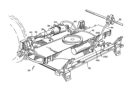
The twin axle br~ke 24, as shown in Figure 2, consists of a
pair of brake beams 30, 32 and a single actuator 34 equipped with
double-acting slack adjuster 36 and cable 38 operated parking
brake. The actuator 34 is supported by, and lies along side, beam
30 and operates to spread a palr of bell cranks 40, whose ends are
attac-ned so as to drive the opposite brake beam 32 against its
wheels, The pivot points of the bell cranks 40 in the master bea~
30 react the equal and opposite force generated by this action
which pushes the master beam up against its wheels.
The 17~ total available stroke of the actuator is sufficient
to permit tbe beams to mount 2-1/2A brake shoes and to operate
without adjustment through the life of these shoes and through a
full cycle of wheel wear.-
-- 6 --
- . 12691;~5
The combined reservoir and triple valve 100, as shown in
Figure 2, is designed to be mounted to the truck bolster and
connected with armored hoses 42 an(i 44 to both the brake actuator
and the brake pipe respectively. The triple valve is compriseà of
three die castings and includes: a simple triple valve to produce
service brake cylinder pressure, an emergency equalizing valve to
provide high brake cylinder pressure in emergency, and an inshot
valve to produce rapid filling of the actuator followed by a
controlled brake cylinder pressure rise, which should be
particularly important in an emergency brake application.
In connection with the triple valve portion, it should be
noted that no release insuring quick service or emergency brake
pipe related ~unctions are included. When brake pipe pressu~e
reduces to zero, the triple valve reacts by raising the brake
cylinder pressure approximately 15~ higher than the value attained
at full service equalization. This will be described in detail
below with respect to Figure 4.
To provide cars having high gross-to-tare weight ratios with a
more even braking ratio over the entire load range, the triple
valve lOO brake equipment includes an optional empty load fixture
200, as shown in Figure 2. Because of the location of the basic
triple valve portion of the truck bolster, the empty load fixture
can be added by simply replacing a blanking plate with the
additional portion as shown in the figure. The empty load portion
has a load arm 202, which can be connected to, or rest upon, the
--` 126~125
truck frame spring basket so as to detect empt~ or loaded
condition by the height of the bolster relative to this basket.
Since this dimension is unaffected by centerplate or side bearing
wear or truck swiveling, it provides a reliable, repeatable
measure of ~pr~ng deflection and, therefore, c~r load.
In operation, the empty load fixtures oper~-te on the
proportioning principle, except that the dummy reservoir is on the
high pressure rather than the low pressure siàe of the
proportioning valve, resulting in its volume h~ving to be only 69
cu. in., which volume is easily enclosed in th~ empty load portion
itself.
The brake pipe modulation group 300, in Fi~re 3, consists of
an E-l modulation valve 302 and KM-2 vent val~ 304 mounted to the
ends of a 10 x 20 release reservoir 306. The ~nctions of this
valve are to provide all of the brake pipe st~llizing and
accelerating features of both the service and emergency portions
of the present ABDW control valve. In particu~r, the following
are carried out:
a~ The quick service function detects br~ pipe pressure
reductions beyand a fixed amount and opens bra~ pipe to a quick
service volume so as to produce rapid serial t~nsmission of
service application and assure a minimum brake~pipe reduction
~ ) An accelerated application valve provl~es continuous quick
service activity for brake pipe reduction at ~ service rate beyond
quick service.
1269~25
c) An accelerated release valve provides ~a dumpback to brake
pipe of the 1600 cu. in. release volume, any time brake pipe
pressure rises more than a fixed amount, whethier as a result of
service or emergency release.- There is no accelerated release
after emergency because the 318 cu. in. of air stored in the two
actuators on a typical car would provide a nesligible improvement
in brake pipe release when compared with the ~256 cu. in.
available on a 10 x 12 cylinder at 8~ piston travel.
d) Rapid transmission of emergency brake application from any
cause is propagated solely by the KM-2 vent v~ve portion.
TRIPLE VALVE 100
The triple valve 100 as illustrated in Fi~re-4 includes three
devices: the ~A~ triple valve 102, the ~B~ emergency equalizing
valve 104 and a brake cylinder inshot valve 1~l6.
Positions of the triple valve are release ~nd charging,
service, service lap and emergency. During b~;h service and
emergency brake application, there is both a f~rst and second
stage of brake cylinder pressure development cD;ntrolled by the
inshot valve lU6. In emergency, a third stage of development
increased brake cylinder pressure by approximæ~ely 15% above full
service.
Operation of the equipment for each of the above positions is
as detailed below.
_ g _
12691Z5
In the release and charging position, brake pipe air from the
brake pipe enters triple valve 102, through pas~age 14 to Chamber
A, moving the valve stem 121 downward and flows through Passage
112 to equalizing reset piston, chamber C, a~d ~hrough Passage 113
to the underside of the emergency reservoir cha~ging check 122.
A-r flowing through this check 122 and Passage 114 charges the 150
cu. in. emergency reservoir and.flows by Passa~ 114a to the
emergency equalizing valve spool 123 where it t-s blocked. Note
than when the triple valve piston 124 moves do~ward, Pilot Pin
125 raises the auxiliary reservoir charging ch.e~k 126 from its
seat, permitting brake pipe air to flow from C~amber A through the
open charging check 126 and the hollow stem o-f- ~;he triple valve
piston 124 into ChamDer B, below the triple pis~on 124, from
whence it flows through Passage 116 into Chamb.e~ E to the lower
face of the emergency e~ualizing valve piston ~32 holding this
valve in its upper position. From Chamber E, air flows through
Passage 115 to the emergency equalizing valve. s~ool 123 and
simultaneously through Passaqe ll5b to the 650- ~. in. auxiliary
reservoir.
With.both reservoirs charged, pressure acr~ss the triple valve
piston 124 will equalize; and it will move upwa~d allowing the
charging check 126 to close cutting off commun~ation between the
brake pipe and auxillary reservoir. This is t~ release lap ~
position of the triple valve 102.
-- 10 --
~Z69125
Note that with the emergency equalizing va~v~ 104 in its upper
position, air from Passage 115 passes upward thr~ugh the hollow
123a of stem 123 of this valve through Passage ~il7 to Chamber G of
the closed brake cylinder supply valve of the ~iple valve 102.
During a service application of brakes, br~k~ pipe pressure
reduction in Chamber A will cause the triple va~!~e ste~ 121 to
move upward, unseating the supply valve 127 fro~ its outer seat
and connecting auxiliary reservoir pressure fro~ Chamber G past
the supply valve seat to Passage 118, through ~ch it flows to
the top of the open inshot valve check 128, thra~gh this valve to
Chamber H, thence, through Passage 119 and the ewpty load blanking
plate 129 to brake cyiinder.
srake cylinder air is also fed back through ~assage ll9a to
Chamber F above the emergency equalizing valve ~4.
: As brake cylinder pressure continues to bui~d up during a
second stage of a service or emergency applicat~n, it passes
through Chamber H of the open inshot valve chec~ 128. When
sufficient air has flowed into the brake cylind~ to raise its
pressure to approximately 15 psi, the diaphragm ~iston 130 of
Chamber H moves down allowing the inshot valve c~eck 128 to
close. Further build up of brake cylinder press~re is under the
control of Choke z. Thus, inshot valve 106 is a variable flow
rate valve allowing high flow during the initial stage of ~rake
pressure build-up and a low flow rate in the la.~ter stages.
lZ~9125
As air flows from the auxiliary-reservoir to the brake
cylinder, the pressure in Chamber B, beneath the triple valve,
piston 124 falls until it nearly equals that o~ Brake Pipe in
Chamber A, at which point the v~lve stem 121 w~ll move downward
and allow the supply valve 127 to close on its outer seat. This
will prevent the supply of further auxiliary reservoir air to
brake cylinder and, hence, terminate the reduction of pressure in
the auxilia-ry reservoir and Chamber B, placing the valve 127 in
service lap position.
With the supply valve 127 initially in the service lap
position, any increase in brake pipe pressure will cause the
pressure in Chamber A to rlse above Chamber B, wnich will pull the
triple valve ste~ 121 down away from the supply valve 127, opening
the inner seat and permitting brake cylinder air to flow back
through the inshot check valve 128, opening it, hence, through
Passage 118a and 118 past the open supply valve inner seat,
thence, through the hollow 131 of stem 121 of the triple valve 102
to atmosphere. Simultaneously with the above, brake cylinder
feedback pressure in Chamber F will reduce through Passage ll9a
along with brake cylinder.
Note that reduction of brake cylinder pressure in this manner
does not upset the balance of brake pipe pressure over auxiliary
reservoir, and the triple valve ln2 remains in its release
position until brake cylinder pressure reduces to zero.
- 12 -
~Z6912S
Note also that if the brake pipe pressure is only slightly
higher than auxiliary reservoir, the supply valve 127 inner seat
will be open; but because of the length of the auxiliary reservoir
charging check valve pilot pin 125, the charging check 126 will
remain on its seat preventing premature charging of the auxiliary
reservoir and, thus, assuring that no air will be trapped in the
brake cylinder. Only when a slightly greater pressure exists in
the brake pipe than in auxiliary reservoir will the triple valve
stem 121 be forced downward sufficiently to open ~he charging
valve 126.
A modification to the triple valve could be made in which
further travel of the triple valve downward would lead to a
retarded recharge position on cars near the head ~f the train.
However, the 650 cu. in. auxiliary reservoir take~s so little
charging air that this may not be necessary.
In an emergency brake application, brake pipe pressure is
suddenly reduced to zero. Triple valve 102 acti~ is identical
with that described above under service brake application, and a
15 lb. inshot of air to the brake cylinder will ~e made prior to
closing of the inshot valve check 128, as in serv~ice From the
point of closing of the inshot valve check 128 u~il brake
cylinder pressure rises to within 2 psi of auxil ary reservoir
pressure, brake cylinder pressure development is affected only by
the triple valve 102 and inshot valve check 128. Note, however,
that when brake pipe pressure is reduced to zero in the emergency
_ 13 -
lZ691~5
application, pressure in chamber C beneath the eme~gency
equalizing valve return piston 133 is also reduced to zero,
allowing the spring in Chamber D of this diaphragm piston 133 to
move it down so that it no longer holds up tbe emergency
equalizing valve stem 123. The emergency equalizing valve 123
will, however, be held up by the differential of a~xiliary
reservoir in Chamber E over brake cylinder pressure in Chamber F.
When brake cylinder pressure in Chamber F rises to within 2
psi of auxiliary reservoir pressure in Chamber E, ~he emergency
equalizing valve stem 123 will begin to move down~ard under the
influence of emergency spring 134 in Chamber J. C~amber J is
connected to atmosphere through choke Y and the s~ll hole 135
through the center of the equalizing valve stem 1~ to Chamber K
beneath the spool 127, opening 137, and Chamber ~ aDove the
emergency equalizing valve return piston 133. Whe~ the emergency
equalizing valve stem 123 begins to move downwardt supply valve
air in Passage 117 flows upward through Passage 117a; and at the
first motion of the emergency equalizing spool 12~ downward,
Passage 117a is connected to Chamber J past the up~er land of the
emergency equalizing valve spool 123, causing auxillary reservoir
pressure present in Passage 117 to vent into Chamb,er J where it
acts on the top of the emergency equalizing valve stem 123 urging
it rapidly downward. since Choke Y is much smaller than the
passage 117a admitting this air to Chamber J, presure developing
in Chamber J assures full motion of the emergency equalizing spool
123 downward until its motion is stopped by the ru~ber seat 136 at
the bottom of Chamber K.
- 14 -
iZ691~5
When the emergency equalizing valve rests on th~s seat 136,
communication through Choke Y to atmosphere through ~penings 137
is blocked and brake cylinder pressure is maintained in Cham~er F,
where along with spring 134, it continues to hold t~e emergency
equalizing valve 123 downward against its lower.seat 136.
Motion of the emergency equalizing valve stem 123 to its lower
seat cuts off communicatiOn via Passage 115 of auxi~ary reservoir
to brake cxlinder and the hollow 123a of the emerge~y equalizing
valve stem 123. In its lower position, this hollow stem 123a of
123 is connected to the emergency reservolr providi~ passage of
air to the brake cylinder from the emergency reserv~. Thus,
using emergency reservoir air only to increase brake ccyinder
pressure and not wasting it by needlessly increasin~ ~xiliary
reservoir pressure as in earlier components with the ~mergency
equalizing valve in its lower position, emergency re~ rvoir air
flows through the hollow 123a of stem 123 of the eq~21izing valve
to Passage 117, thence, past the open supply valve t~ ~assage 118,
and through Choke 2 of the inshot valve check 128 t~ ~he brake
cylinder, addlng a third or high pressure phase to ~ake cylinder
pressure development.
With the brake applied in emergency, brake cyli~er pressure,
. with an initial 70 psi brake pipe, would be 60 psi; auxiliary
reservoir pressure would be 50 psi (lower than brake cylinder~
because of the emergency equalizing valve). Thus, w~en brakes are
released, the brake pipe need only be restored to s~ething above
91~S
5~ psi to raise the pressure in Chamber A above the auxiliary
reservoir pressure in Chamber B. This reduced brake pipe pressure
.. requirement, along with the..dumpback of.air from the modulating
valve 300 should overcome the.need for the present accelerated
emergency release feature.
As with service release, when the triple valve ~iston 124
moves down, it unseats its hollow spool 131 from the inner seat of
the supply valve 127, permitting brake cylinder alr to flow from
brake cylinder to Passage 119 back through the insh~ check valve
128, unseating this check 128, through Passages 118~ and 118 and
past the inner seat of the supp~y valve 127 to atmosDhere through
the hollow center 131 of the triple valve piston.
This action reduces brake cylinder pressure at 2 Iate
independent of inshot cho~e z. As brake cylinder pr~ssure
reduces, so does the pressure in Chamber F above the emergency
equalizing valve 132. At the same time this pressure is be ng
reduced, pressure in Chamber C, beneath the emergency equalizing
valve return piston 133, is acting to force the emergency
equalizing valve 123 upward to its service position When the
brake cylinder.pressure in chamber F above the emer~ncy
- equalizing valve piston 132 drops to the point where the comblned
effort of auxiliary reservoir pressure in Chamber E and return
piston pressure in Chamber C are sufficient to urge it upward, it
will begin to move upward and will cut off communic~tion through
Passage 117a to Chamber J allowing Chamber J pressure to reduce to
- 16 -
lZ69125
atmosphere through Choke Y, assuring that once the emergency
equalizing valve 123 has started to move upward, this motion will
be continued_to its upper most stop and the release position,
Finally, when brake cylinder pressure drops below 15 psi, this
pressure acting in Chamber G will no longer be sufficient to keep
the inshot valve piston 130 down and will allow this piston 130 to
move up, aiding the back flow of air to keeping open the inshot
valve check 128 and assuring complete release of brake cylinder
air to the atmosphere.
Charging of the 650 cu. in. auxiliary reservoir will begin
when sufficient differential of brake pipe pressure over auxiliary
reservoir pressure exists to open the charging check 126 in the
triple valve stem, and charging of the 150 cu. in. emærgency
reservoir will resu~e when auxiliary reservoir press~re has been
restored above 60 psi so that pressure can flow from ~assage 2
through Chamber C and the emergency reservoir chargi~g check 122
to recharge this 150 cu. in. volume,
EMPTY LOAD FIXTURES 200
In the event that an empty load brake system 200 is requried,
- the empty load blanking plate 129 shown in Figure 4 ~y be removed
and the empty load device 200 shown diagrammatically in Figure 5
is mounted to it with the load arm 202 connected to the car as
shown in Figure 2. This valve contains a simple ra~ioing valve
204, lock over piston 206, change over valve 208 and dummy volume
210, as shown in Figure 5, and operates in the following manner:
-- - 126912~
~ hen a brake application is made, brake cylinder p~essure
enters from the triple valve in Passage 221 and flows ~o Chamber A
on the left side of the ratio valve. Simultaneously, air flows
through Passage 211a to the semi-circular area on top ~f the
change over valve key 208. In the event that the car is light,
the load arm 202 will be positioned downward; and brak~ cylinder
air will flow from Passage 211a past the key 208 to P~ssage 213,
thence to ~hamber C on the right hand side of the lock over piston
206. Moving this piston 206 to the left requires onl~ 5 psi or
less; and in its left most position, the piston is de~nted by an
annular spring engaging a detent groove.
As air pressure continues to rise in the supply pressure in
Chamber A on the left hand side of the ratio valv~ 204 ~xerts less
force on the spool of this valve 204 than does the bra~e cylinder
pressure in Chamber B on its right hand side, forcinq ~e double
piston spool to the left against the ratio valve seat at a ratio
of S0, 60 or 70~ of input pressure, as determined by t~
particular diaphragms used. As supply pressure from ~ triple
valve continues to rise, Chamber A pressure will bui}d ~p, forcing
the spool to the right, allowing further passage of air through
the hollow spool to Chamber B causing it, again to close, with
Chamber B pressure always at the desired rat'o to Cham~er A
pressure.
- 18 -
. lZ~912S
Air also flows from Chamber A through Passage 211b and the
unseated dummy volume cut-off check valve 230 into Passage 212 and
the dummy volume 210~ since the dummy volume 210 is on~y 69 cu.
in., this volume will accept the additional air supplied by the
triple valve and not needed by the brak~ cylinder at the lower
pressure of the ratio valve 204, thus, bringing about an equal
reduction in auxiliary reservoir pressure in response ~o brake
pipe pressure reduction whether the car is empty or loaded. Thus,
at final equalization in either service or emergency, the output
pressure of the triple valve in Passage 2il will be exactly the
same, whether the car is loaded or empty. Brake cylinder
pressure, however, whéther service or emergency, will he 50, 60 or
70% of that provided by-the triple valve as determined by the
ratio of Chamber A area to Chamber B area.
Note that during the above light, car operation, brake
cylinder air from Chamber B also flows through 114a to the face of
bypass check valve 232 but cannot open this valve because of the
higher supply pressure behind it, which holds it to its seat.
When brake cylinder pressure is released, air flows from
Chamber A out to the triple valve, through the triple valve, and
to atmosphere causing the ratio valve 204 to close more tightly to
its seat. However, air from brake cylinder in Passage 214 can
flow through Chamber B, through Passage 214a, and will unseat~the
bypass check 232 because of its differential over the now reduced
supply pressure in Passage 211c. Thus, during release, brake
-- 19 --
~Z691ZS
cylinder pressure flows from brake cylinder into Passage 214,
through Chamber B, Passage 214a, past the bypass check valve 232,
unseating it, into Passage 211c, Passage 211b, Chamber A, and out
Passage 211 to the triple valve and exhaust.
If the car weighs heavy, the load arm 202 will be moved upward
to Position C; and Passage 211a will be connected through the
changeover valve key to Passage 215. Brake cylinder air will,
thus, enter Chamber D on the left side of the lock over piston
206, forcing it to the right, in which position it will be
detected, forcing the bypass check 232 off of its seat and
allowing the dummy volume cut-off check 230 to move to its seat.
As air pressure builds up in Passage 211 and Chamber A where,
again, it flows through the hollow piston rod of the rat o valve
204 to Chamber B and the brake cylinder and, again, forces the
ratio valve to the left. ~owever, with the lock over piston 206
in its right hand position, air can flow from Chamber A through
Passages 211b and 211c and past the opened bypass check into
Passage 214, Chamber B, and out to the brake cylinder,
Slnce the dummy volume 212 is not desired cut in, as all air
suppl~ed by the triple valve in the loaded position must be passed
to the brake cylinder, the dummy volume cut-off check 230, which
is permitted to move to its seat by the lock over p ston 206, will
do so and prevent unnecessary loss of air to the dummy Volume-210.
- 20 -
- ~Z6~Z~i
When brak~s are released afker an application with the empty
load fixtures in the loaded position, air flow out of the valve is
exactly the same as in the empty position with the eXCeption that
brake cylinder pressure does not have to move the bypass check 232
off of its seat as it is held open by the lock over piston 206 in
any case.
E-l BRAKE PIP~ MODULATION VALVE 302
The purpose of the E-l brake pipe modulating valve 302 shown
in Figure 3 and diagrammatically in Figuré 6, is to provide quick
service propagation of an initial service application and to
provide a continuous quick service function. A third purpose is
to control the storage and release back to brake pipe of air in a
release volume so as to provide accelerated release of brakes
after both service and emergency brake applications.
The only connection to the E-l brake pipe modulating valve 302
is to the brake pipe and the augmentation of brake pipe pressure
change it provides will be comparable to those in the AB, ABD and
ABDW type control valves.
When charging this valve 302, air flows initially from brake
pipe by passage 311 to the underside of accelerated release valve
piston 320, Chamber A, thence through Passage 316 to Chamber C on
the underside of accelerated application pilot v21ve piSton 322.
Air from Chamber C flows through Quick Action Chamber Charging
Choke Y and Passage 317 to the quick action chamber 308, and
- 21 -
12691~5
Passage 317a to the back of the accelerated application pi~ot
valve check valve 324. Air flowing through Choke Y is at ~uick
action chamber pressure and is communicated via Passage 317b to
Chamber D, above the accelerated application-pilot valve piston
322 and Chamber B, above the accelerated release valve piston 320.
Note that brake pipe pressure in Passage 316 also flows
through Passage 316a to Choke z and to the face of release
reservoir c~ontrol check 326 through Passage 316b. Brake p~pe air
flows through Choke z into Passage 318 and the underside o~ the
accelerated..release check 328, thence past this check 328 into
Passage 319 whence it charges the release reservoir and through
Passage 319a to Chamber F above the quick serYice limiting valve
piston 330.
W~th the equipment fully charged, pipe pressure may be reduced
to initate a brake application. When such a reduction is begun
simultaneous reduction of pressure in Chambers A, C and E occurs.
No motion of the quick service limiting valve 332 will Occur
because it is held up by a 3 psi differential spring 334 in
Chamber G. The accelerated release valve piston 320 will
initially be resting on the stabilizing spring cage 336, having
permitted the accelerated release check 328 to close at the
termination of release reservoir 306 charging. The accelerated
release valve piston 320 will not move down until the brake pipe
pressure drops about 1/2 psi and will not move down until the
stabilizing spring has been overcome. When this occurs, the
- 22 -
lZ6~ 5
accelerated release valve diaphragm piston 320 will mov~ do~n
opening the quick service check valve 338. When the quick service
check valve 338 is moved off its seat, brake pipe air will ~low to
the quick service volume 340; and because of the proximity ~f the
quick service check 338 to Chamber A, this flow will cause a
further downward motion of the accelerated release valve piston
320, thus, assuring that the quick service check 338 will o~en
wide, permitting brake pipe pressure to flow from braKe p-pe
through Passage 311, Chamber A, Passage 312, past the open ~uick
service check 338 to the quick service limiting valve spool 332,
hence, into the quick service volume 340.
Initial flow of air will be rapid enough to propagate this
quick service action to the next car and will terminate when 2 3
psi differential of release reservoir pressure over brake p~pe
pressure is established, which differential will move the quick
service limiting valve spool 332 down cutting off further
communication with brake pipe through the quick service check 338.
At this same time, accelerated application p~lot valve piston
322 also moves down forcing its check 324 from its seat and
permitting quick action chamber 308 air to flow from Passage 317a
past the open check valve 324 to atmosphere through Choke U, while
' subjecting the inner area of the accelerated application valve
diaphragm 342 to the pressure backed up by Choke U.
If this backed up pressure is sufficient, it will cause the
accelerated application diaphragm 342 to move downward from its
- 23 -
1269125
seat exposing the larger-outer area and permitting the upper
accelerated application check valve to seat 344, cutting off
communication between brake pipe in Passage 312 and the already
charged bulb volume 346. As long as the accelerated application
pilot valve 322 is down, permitting quick action chamber 308 air
to flow to atmosphere, the accelerated application valve p Ston
342 will be held down by air acting over its full upper diaphragm
face, and will drain the bulb volume 346 through Passage 314 and
its lower check valve 348. When quick action chamber 308 pressure
reduction exceeds that of the brake pipe, the accelerated
application pilot valve piston 322 will rise, allowing its chec~.
324 to close and cut off the supply of quick action chamber 308
air to the accelerated application valve piston 342 which will
allow its upper chambers to drain through Chokes U and T. Thls
action will allow the accelerated application valve piston 342 to
move upward, returning its lower check 348 to its seat to prevent
further draining of the bulb volume 346 and reopening its upper
check 344, thus, reconnecting the drained bulb volume 346 to brake
pipe causing a controlled volume of air to be withdrawn from it,
thus, causing a further reduction of brake pipe pressure by
allowing Passage 312 to communicate past the upper check 344 to
Passage 313 and through Choke V wi~h the now drained bulb volume
346. After quick service activity has terminated, any time brake
pipe pressure is reduced,-the accelerated application pilot valve
piston 324 will, again, move down triggering this sequence o~
events much the same way the accelerated application valve
operates on the present ABDW emergency AAV portion.
- 24 -
- ~Z69125
Whenever brake pipe pressure rises above quick action chamber
pressure in Chamber B by more than a predetermined amount,
accelerated release valve piston 320 will be moved upward and
unseat the accelerated release check 328. This action will dump
accelerated release volume 306 back to brake pipe, aidins in the
restoration of brake pipe pressure by way of Passage 319, past the
open accelerated release check 328, Passage 318 and 318a, through
the release control check 326 bypassing Choke z, into Passage 316a
a~d 316b, Chamber A, and out Passage 311 to the brake pipe. At
the same time, the motion of the accelerated release valve plston
320 upward allows the quick service check 338 to seat, preventing
the exhaustior. of brake pipe air when the quick service limiting
valve 332 returns to its upper position. As brake pipe pressure
recharges and accelerated release reservoir air pressure
decreases, the differential of Chamber A over Chamber B in the
accelerated release valve will be decreased; and when brake pipe
pressure is less than S ps~, higher than accelerated release check
328 pressure, the accelerated release check 328 spring will return
this check valve 328 to its seat and the E-l brake pipe modulating
valve 302 will be returned to its fully charged position. Above
this pressure, brake pipe pressure can only be supplied from the
locomotive; and when a further 3 psi has been built up in the
brake pipe, its pressure will be higher than accelerated release
reservo-r pressure and accelerated release reservoir 306 rechar~e
will begin through Choke Z and the accelerated release reservoir
charging check 328.
.
- 25 -
~Z691ZS
From the preceding description of the preferred embodiments,
it is evident that the desired objects are attained in that
reduced size reservoirs are mounted directly to the triple valve
which are mounted on each truck. The accelerated application and
release functions are separat~ from the triple valve and are
distributed throughout the train.
Although the invention has been described and illustrated in
detail, it is to be clearly understood that the same is by way of
illustration and example only and is not to be taken by way of
limitation. The spirit and scope of the invention are to be
limited only by the terms of the appended claims.
-26 -