Note: Descriptions are shown in the official language in which they were submitted.
The present invention refers to a device for contact-
free pivoting of a pivotable structural member about a hinge
axle, e.g. a door or a lid of an object moveable along a path,
under the effect of the magnetic force from at least one magnet.
During sequential production of passenger cars, and
particularly durin~ surface treatment with aid of robots, it is a
requirement to be able to paint the car body externally as well
as internally without marring the fresh-painted surface. This
means that is must be possible automat1cally to open and close
the doors of the car body, without causing any marks on the
freshly painted doors. This problem has hitherto been solved
with a robot, which e.g. is programmed to find a specific place
on the door, e.g. a bore, in which the lock components are
intended to be affixed, and where the robot with aid of a tool
pulls the door towards itself and after termination of the paint-
ing also closes the door. A prerequisite for this opening and
closing operation is that the car body is positioned rather accu-
rately relative to the robot, which in turn means that it has to
be so complex as to be able to make the rather complicated motion
pattern required for the opening and closing. Robots of this
type are very expensive and they furthermore take up a great deal
of space.
The same or similar problems will arise at other work-
ing areas in the car industry, e.g. on applying putty, or
assembly and, of course, also in other industries.
It is known (Swiss Patent 534,797) to open a door of a
building using electro magnets, which are recessed in a door leaf
and the magnet poles of which are facing the floor, where they
cooperate with ferromagnetic blocks recessed in the floor. By
activating the magnets successively with programming equipment, a
displacement is obtained between the blocks.
The present invention provides a manipulator which con-
1 --
tact-free can open and close a car door, a motor hood or a trunk
flap. The same manipulator, if so desired, is able first to open
one door, e.g. the front seat door and thereupon, after a move-
ment of either the car body or the manipulator, to open the
other, rear sea-t door. The manipulator requires little space and
is locatable e.g. completely or partly below the car body, when
the body ls transported on a conveyor system. Rather big toler-
ances are allowable at the positioning of the car body relat ve
to the manipulator. According to the present invention the mag-
nets are located along, but at some distance outside the pivotingarea o~ the struc~ural member, said magnets being arranged via an
air gap to exert a magnetic force on at least one of the limiting
edges of said structural member, e.g. its lower and/or upper
edge, and the magnets are moveable along a predetermined path, or
are fixedly arranged in a pattern, such that on relative motion
between the car body and the magnets, the structural member is
sub;ected to a pivoting movement about its hinge.
According to the present invention therefore there is
provided a device for contact-free pivoting of a structural mem-
ber about a hinge using the attractive force of at least one mag-
net, said hinge being mounted on an ob~ect moveable along a
transport track, in which said at least one magnet is located at
a small distance outside the area over which the structural mem-
ber is pivotable, said at least one magnet is arranged to exert amagnetic force over an air gap on at least one of the limiting
edges of said structural member and said at least one magnet is
moveable along a predetermined path, or is ~ixedly arranged in a
pattern which causes, on relative movement between ob;ect and the
magnet, the structural member to be sub~ec-ted to the magnetic
force tending to pivot the structural member about said hinge.
In one embodiment of the present invention each magnet
is disposed upon a manipulator comprising an arm plvotable about
an axle, the manipulator and each magnet being located outside
the area of pivoting of the structural member at a small distance
from the structural member, the manipulator or the structural
member being arranged to be positioned relative to each other
such that their axles of pivotlng are substan-tially in the same
plane and the manipulator being pivotable about its pivot axle
either by means of an actuator or by the motion o~ the passing
structural member under the effect of the magnetic force. Suit-
ably the pivoting axles are axial extensions of each other.
Desirably the arm or said at least one magn2t is vertically move-
able and adjustable to different angular positions relative to
the structural member by actuators in order to maintain a con-
stant air gap between the at least one magnet and the structural
member and for pivoting the arm away from the structural member
when the magnetic force acting upon the structural member is to
be interrupted. Suitably upon the arm or the at least one magnet
there are arranged transmitters for measuring the distance
between the at least one magnet and the structural member to gen-
erate a measurement signal used as a control s~gnal for the
ad~ustment of the height and inclination position of the arm.
Desirably there are two transmitters. Suitably an angle trans-
mitter is arranged between a frame and the manipulator arm forpositioning the angle of the arm relative to the frame by means
of an actuator. Desirably a plurality of said magnets are
enclosed in a non-magnetic protective casing arranged to rest
upon pressure sensitive transmitters, which are adapted to emit a
control signal, for bringing about a lowering of the manipulating
arm on collision between an upper side of the protective cover
and the ob;ect.
In another embodiment of the present lnvention the
angular position of the at least one mag~et relative to the
structural member is self-adjusting to a limlted extend under the
effect of the magnstic forces. Suitably the manlpulator is move-
able, substantially parallel to the direction of movement of the
object. Desirably the manipulator is moveable along a track sub-
stantially parallel to the direction of movement of the object.Suitably the device includes a plurality of block shaped perma-
nent magnet arranged on a ceramic block, which is supported bythe manipulator arm made of soft iron. Desirably a plurality of
sald magnets are stationary and the structure member besides
being pivotable about a hinge is also linearly moveable, and the
magnets are vertically adjustable and arranged in a pattern, sub-
stantially corresponding to the path of the structural member,
whereby the substantially linear movement of the structural mem-
ber along a conveyor track causes a pivoting thereof about its
hinge.
The invention will hereinafter be further described
with reference to the accompanying drawings, in which:-
Figure 1 is a perspective of a portion of a passenger
car body and a manipulator according to o.ne embodiment of theinvention during the opening or closing thereof;
Figure 2 is a section through the lower portion of a
car door wi.th the magnet arm of the manipulator in position for
opening the door;
Figure 3 is a side view of a manipulator according to a
first embodiment of the invention;
Figure 4 is a side view of a manipulator according to a
second embodiment of the invention;
Figures 5 and 6 are respectively a side view and a view
from above of the device according to a third embodiment of the
invention;
Figure 7 is a perspective view of a simplified embodi-
ment, developed particularly for closing car doors;
Figures 8 and 9 show srhematically in plan the closing
process with the device according to Figure 7, and
-- 4
; .. ...
' ' ' ' ' 1 . '
3~
Figure 10 shows in plan a manipulator according to the
invention with s-tationary magnets arranged for opening as well as
closing a structure member.
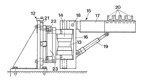
The manipulator 11 according to the invention comprises
a frame 12, which supports an actuator 13, e.g. in the form of a
pivoting hydraulic ~ack (shown in Fig . S 1, 3 and ~) or a recipro-
cating piston-cylinder device (Fig.s 8 and 9) and which is arr-
anged to pivot a bracket 15 articulated to the frame 12 around a
pivot axle 14. In the embodiment shown in Figures 1 and 3 the
bracket 15 comprises a carrier 16 and an arm 17 plvotably suppor-
ted about a horizontal axle 18 and the horizontal or inclination
angle of which arm 17 is ad~ustable by means of a servo mechanism
19. This servo mechanism 19 is articulatedly connected to the
carrier 16 and also to the arm 17. On the upper side of the arm
17 there is fitted a plurality of magnets 20 in such a manner
that their poles are facing upwards towards a structural member
25 situated at some distance therefrom and which, e.g. may be a
door ~Fig. 1l, a flap or a hood. The manipulator is arranged
outside the pivot area of the structural member 25, such that
only a small air gap separates the structural member from the
manipulator, when activated.
Where the manipulator has to be adaptable to height
variations in the ob~ect to be acted upon, the frame 12 of the
manipulator is provided with a vertically and laterally ad~us-
table plate 21, which by means of a horizontal hinge 22 supports
a carrier 23, on which the actuator 13 is mounted. The actuator
13 thus can be adjusted vertically, laterally and as to its
inclination to the horizontal plane.
The manipulator is developed particularly for contact-
free opening and closing of the doors 25 of a passenger car body
24, which is transported upon a conveyor (not shown) and which
forms an important part, e.g. of an automated surface treatment
system, where painting is carried out by robots~ The manipula-
;,
tor, of course, can also be adapted to other working functions.Depending upon how the working process is to be accomplished
there may be a manipulator on each side of the car body. The
manipulators can be programmed in such a manner that they each
first open and then close one front seat door and repeat the same
procedure on the rear seat door after a movement of the car body.
It is, however, also possible to arrange a manipulator for each
door, and if the painting is made accordlny to the line produc-
tion principle it is possible to design the manipulators such
that they will perform a travelling motion synchronized with the
motion of the car body. Another alternative is that a manipula-
tor is intended only for opening the doors and another manipula-
tor has been assigned the closing function.
The manipulator ll has such a small height, that it can
be accommodated mainly below the car body 24 transported on a
conveyor track. The position of the manipulator relative to the
car body 24 is therefore chosen so that the manipulator arm 17
will be situated just in front of and below the door 25 to be
opened. It is thus not absolutely necessary that the hinge axle
26 of the door 25 is aligned wlth the vertical pivot axle 14 of
the manipulator, but certain variants can be accepted. Due to
the demand for contact-freeness and a reliable function it is,
however, essential that these two axles are mainly parallel.
In the manufacturing phase in which the car body is to
be painted, the locking means of the car is not yet installed and
the door is held in closed position by means of sprlngs in the
door or by a temporary magnet fixture. When opening the door it
is therefore necessary to overcome this spring or magnetic force,
and as the door in a previous operation has obtained an external
layer of paint, is it imperative that the surface is not touched.
For these reasons the manipulator arm 17 with the magnets 20 is
located at such a short distance below the lower edge of the door
as possible. A free air gap of e.g. 5-20 mm at a certain given
magnetic force has proven itself to be appropriate, also in view
of height variations of the car bodies. The magnets 20 are thus
located upon the arm 17, so that a concentration of the field
lines is achieved above them. If horseshoe-shaped permanent mag-
nets are chosen the poles will face the lower edye of the door
25. A pivoting of the arm 17 by means of the actuator 13 results
in the magnetic force opening the door and pivots it to open
position, which has been pre-programmed in the control equipment
for the manipulator (not shown). The door can either be closed
by the same manipulator or the car body can otherwise be moved to
the consecutive working area, e.g~ in order to paint its rear
doors, whereby the closing is made by a manipulator particularly
assigned this function. Independent of the working task given to
the manipulator, the arm after termination of the opening or
closing movement, can be pivoted about the hinge axle 18 in a
direction away from the door, such that the air gap will be so
large that the magnetic force is interrupted. The arm can return
to its initial position after the car body has been moved.
Instead of tilting the arm 17, such as shown in the
embodiment according to Figure 3, the arm 17 together with actua-
tor 13 can also be vertically displaceble along guides 27 pro-
vided on the frame 12. This displacetnent motion is then effected
with an actuator 28, in accordance with what is shown in Figure
4.
The embodiment according to Figures 5 and 6 differs
from the embodiments shown in Figures 3 and 4, in that the arm 17
carries an actuator 19 and 28 at each of its front and rear ends,
e.g. hydraulic piston cylinder devices, the piston rods of which
carry a magnet carrier 33, preferably of soft iron and a pack of
magnets 34 consisting of a ceramic magnet block 35 upon which is
rigidly fixed magnet bodies 20, preferably from a metallic com-
pound of cobalt and rare earth types in order to obtain the high-
est possible magnetic effect. In two of the magnet bodies 20
there are arranged a depression 36 each for a transmitter 37,
which contact-less can sense the position of the magnets in rela-
~ 9
tion to the lower edge of door 25.
As the hinges of the doors 25 cannot be supposed to becompletely free from play and the car body can havs an unstable
position upon the conveyor, it can occur that the lower edge of
the door is situated below the highest permissible heiyht level.
In order to reduce the effects of a collision between the lower
edge of the door and the manipulator as far as possible, there is
arranged over the magnets 20 a protective casing 39 made of a
non~magnetic material, e,g. aluminum, the lower edge of said cas-
ing resting against one or more pressure pulse transmitters 40,
which effect an immediate lowering of the manipulator arm 15 if
the casing 39 should be subjected to a pressure, i.eO if e~g. a
collision with a door should occur. As pressure transmitter it
is e.g. possible to use a liquid-filled hose upon which said pro-
tective casing 39 and which hose at a pressure increase provides
a signal which by the computer is converted into an order for
lowering the arm.
As doors of different car body types have varying open-
ing angles, and also the opening angle can vary between a front
seat door and a rear seat door it is essential that the angle of
the arm 15 relative to the frame 12 can be positioned. ThiS is
preferably achieved by means of an angle transmitter 38, which
can be arranged in a bore in the interior of the shaft ~ournal
14.
The distance from the car body to the floor and thereby
also to the upper edge of the magnets 20 can vary within certain
limits, and it is therefore necessary that th~ air gap between
the lower edge of the door 25 and the upper edge o~ the magnets
can be ad~usted. This is preferably accomplished by means of
said transmitters 37 arranged on the arm 17 or in depressions ln
the magnets, and which contact-free, optically or electrQnically
senses the space between the door and the magnets and via a com-
parator emits a signal to the actuator 19 or 28 for a posltion
-- 8 --
~L~ ~ 9 ~ ~ ~
ad~ustm~nt of the arm 17. Instead of measuring the space it is
also possible, by means of a Hall generator, to measure the
instant magnetic field strength, whlch is proportional to the
size of the air gap.
Certain movements, e.g. closing of a door can be
achieved with a smaller power requirement, and the embodiment
shown in Figure 7 to 9 has been developed for this purpos~. At
this embodiment the manipulator 11 comprises a plate 29, to which
10 i5 affixed a plurality of magnets 20. The plate 29 is pivotable
about a vertical axle 14 relative to a base plate 30, and it is
vertically adjustable by means of a spacing member 31. The
manipulator 11, in the same manner as in the embodiments des-
cribed hereabove, is located somewhat below the door 25 of the
car body 24 and outside its pivoting area, such that a door which
is open, at the transfer of the car body along the conveyor
track, at a certain position will be situated ~ust above the pack
of magnets 20~ Thls will then exert a magnetic attraction force
upon the lower ~dge of the door, which force is so big that the
door, on continued transfer of the car body, will be pivoted con-
currently with the transfer motion of the car body, at the same
time as the plate 29 with the magnets 20 rotate about the axle
14, such that a gradual closing of the door is effected. When
the attractlon force terminates, due to the fact that the door
has passed the magnets, the plate 29 is pivoted back to its ini-
tial position by means of a tension spring 32 or the like.
It is also possible to arrange the magnets 20 to be
stationary, on one or more, preferably vertically ad;ustable
plates 41, such as shown in Figure 10. The magnets are arranged
in a pattern, which corresponds to the movement path the door
performs, when the car body 24 and its door is moved along a con-
veyor track 42 past the maynets. The dnor will be sub~ected to a
lateral magnetic force which provides a pivotin~ of the door from
or towards the car body as the distance to the nearest magnet
20a,20b,20c etc. increases or decreases.
_ g _
:..
,~
The magnets can be electro magnets, if an electric
interruption of the magnet power is desired.
~0
-- 10 --
.