Note: Descriptions are shown in the official language in which they were submitted.
9~1~
CONVEYO~ IN PL~STIC WORKING M~CI-IINE
BACKGRO~ND O~ Tl-iE INVENTION
Field o~ the Invention
This invention rela-tes to a conveyor in a plas-
tic working machine wherein a lower die and an upperdie :Eor cooperatingly per~orming plastic worl<ing oE works
are disposed on each of a plurality of workina stations set
at intervals alon~ the direction in which the works
are conveyed, and an arm provided wi-th a handling
mechanism for holding the works is provided on a
transEer bar disposed sideway of the working sta-
tions for conveying the wor]cs in sequence between
the worlcing stations.
Description of the Prior ~rt
In conveyors oE the above type, an arm is provided
on a trans.Eer bar disposecl on one side of the working
stations and is extended toward the working stations, or
arms are provided on a pair of transfer bars disposed on
both sides of the working stations and are extended toward
the interposed stations.
However, in a construction in which the arm is
supported one-sidedly on -the transfer bar as de-
scribed, vlbrations ma~ be caused to the arm
during conveyance, and thus works cannot be held
securely or may drop unexpectedly in more undesirable
-- 1 --
~9~1~
cases.
Thls Inventlon has been made In vlew of the above
problems, and Its obJect Is to provlde a conveyor In a plastlc
worklng mac~lne capable of stablJlzlng a holdlng state of works
by supportlng an arm double-sldedly.
To attaln such obJect, accordlng to thls Inventlon,
transfer bars are provlded on both sldes o~ the worklng statlons,
and an arm Is brldged between and borne on both transfer bars
wlth both ends thereof movable longltudlnally along the dlrectlon
In whlch works are conveyed or flxed to the transfer bars.
Accordlngly, therefore, the present Inventlon provldes
In a worklng machlne havlng palrs of lower dles and upper dles
dlsposed on a plurall~y of worklng statlons, respectlvely, for
cooperatlvely worklng a workplece at the respectlve statlons, the
statlons belng set at Intervals In a dlrectlon of conveyance of
the workplece, a conveyor whlch comprlses: a palr of transfer
bars spaced from one another a predetermlned dlstance and
dlsposed on opposlte lateral sldes of the worklng statlons and
extendlng parallel to each other In the conveylng dlrectlon, sald
palr oF transfer bars belng unltarlly movable In a vertlcal
dlrectlon and In sald conveylng dlrectlon by respectlve drlvlng
means; a plurallty of arms dlsposed laterally brldglng between
the transfer bars so that each arm extends ~he full predetermlned
dlstance, sald arms, except for at least one arm, belng fixed to
sald transfer bars In a manner non-movable In the conveylng
dlrectlon relatlve to sald transfer bars, sald at least one arm
belng adJustably movable relatlve to the bars in the conveylng
dlrectlon by a drIve mechanlsm; and a handllng mechanIsm provlded
for each arm for holdlng the workplece.
Owlng to such constructlon, slnce both ends of the arm
are supported by the transfer bars, vlbratlon of the arm Is
mlnlmlzed durlng conveylng operatlon of the transfer bars, a work
Is held stably by a handlIng mechanlsm, and thus works can be
conveyed securely.
The abo~e and other obJects, features and advantages of
the Inventlon wlll be elucldated from the followng descrlptlon of
preferred embodiments wlth refernece to the accompanylng
drawlngs.
1 0
1 5
- 2a -
, .
BRIEF DESCRIPTION OF TIIE DRAWINGS
Fig. 1 to Fig. 7 represent a first embodiment
of this invention, wherein Fig. 1 is a general sche-
matic side sec-tional view, Fig. 2 is an enlarged
plan view of a main part of Fig. 1, Fig. 3 is a view
taken on line III - III of Fig. 2, Fig. ~ is an en-
larged sec-tional view taken on line IV - IV of Fig.
2, Fig. 5 is a plan view xepresenting a construction
of a driving means, Fig. 6 is a sectional view taken
on line VI - VI of Fig. 5, Fig. 7 is an enlarged sec-
tional view taken on line VII - VII of Fig. 2; Fig.
8 is a general schematic side sectional view of a
second embodiment which corresponds to Fig. l; Fig.
9 to Fig. 11 represent a third embodiment of this
invention, wherein Fig. 9 is a general schematic
side sectional view, Fig. 10 is an enlarged plan
view of a main part oE Fig. 9, Fig. 11 is a sec-
tional view ta]cen on line XI - XI of Fig. 10; Fig.
12 to Fig. 16 represent a fourth embodiment of this
invention, wherein Fig. 12 is a general schematic
side view, Fig. 13 is an enlarged sectional fiew of
a main part of Fig. 12, Fig. 14 is an enlarged sec-
tional view taken on line XIV - XIV of Fig. 13, Fig.
15 is a sec-tional view taken on line XV - XV of Fig.
14, Fig. 16 is a sectional view taken on line XVI -
`:
-- 3
::
- ;, ,
l~Y~
~VI of Fig. 15; Fig. 17 to Fig. 21 represent a fifth
embodiment of this invention, wherein ~ig. 17 is a
general schematic side sectional view, Fig. 1~ is
an enlarged plan view of a main part of Fig. 17,
Fig. 19 is an enlarged sectional view taken on line
XIX - XIX of Fig. 18, Fig. 20 is a sectional view
taken on line XX - XX of Fig. 19, Fig. 21 is a sec-
tional view taken on line XXI - XXI of ~ig. 20.
DE:TAILED DE:SCRIPTION OF PI~EFEI~I<ED EMBODIMEI~TS
Referring now in detail to the drawings, in
Fig. 1 which shows a first embodiment of this
invention, a plurality oE, for example, first to
fiEth working sta-tions Sl to Ss in this embodiment
are set at regular intervals alony a direction 2
in which a worlc W is conve~ed on a plastic working
machine,for example,on a press 1, and lower dies 31
to 35 and upper dies ~ to 45 for pressing the work
W in collaboration are disposed on the working sta-
tions Sl to Ss~ respectively. That is, the lower
dies 31 to 35 are fixed at regular intervals on a
bolster 6 on a pedestal 5 in the conveying direc-
tion 2, and the upper dies 41 to 45 are suppor-ted
on a holder 3 fixed on an elevator 7 corresponding-
ly to the lower dies 31 to 35. A conveyor 9 is
provided additionally on the press 1, and after a press
working between the lower dies 31 to 35 and the up-
per dies ~I to ~5 according -to a descent of the ele-
vator 7, the conveyor 9 operates to convey the work
W in sequence to the next working sta-tion in the
conveying direction 2.
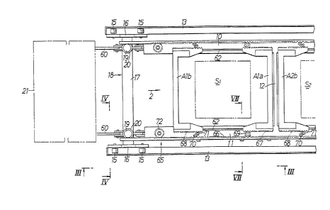
The conveyor 9 has a pair of transfer bars 10,
11 disposed in parallel with the conveying direction
2 on both sides of -the wor]cing sta-tions Sl to S5,
and a plurality of arms ~la, Alb ... A5a, A5b laid
between the transfer bars 10, 11 and movable longi-
tudinally in the conveving direction 2. The work W
is conveyed according to displ~cements of the arms Ala, Alb
5a, ASb and the transfer baxs 10, 11, however,
the worlcing stations Sl to Ss are similar to each other in
their construction, and hence a description will be
given of the Eirst worlcing st~-tion 51 and its neigh-
borhood with reference to the drawings.
In also reEerring to Fig. 2, bo-th
the transfer bars 10, 11 are provided to extend
from the first working station Sl to the fifth work-
ing station Ssl and the transfer bars 10, 11 are
coupled to each other through stays 12 located among the work-
ing stations Sl to Ss. Further, each stay 12 is
disposed so as to come at the center among the work-
ing stations Sl to Ss~ when both the transfer bars
9~9
10, 11 are kept s-ta-tionary at the time of press
working.
In referring further to Fig. 3 and Fig. ~,
guide rails 13 extending horizontally in the convey-
ing direction 2 are disposed on both outsides of the
transfer bars 10, 11, and each guide rail 13 is sup-
ported by a strut 14 provided vertically on a floor
surface. Travelling plates 16 are placed on both
the guide rails 13 through a pair of wheels 15, and
a truck 18 is constituted by coupling both the trav-
elling plates 16 through a connec-ting rod 17. The
truck 18 is capable of running on both -the guide
rails 13 longitudinally in the conveying direction
2, and is arranged on the guide rails 13 correspond-
ingly at least to both ends of the transfer bars 10,
11. Then, guide rods l9 are provided vertically
near bo-th ends oE the connecting rod 17, a cylin-
drical coupllng member 20 is inser-ted movably up
and down in each guide rod 19, and these coupling
members 20 are coupled -to end portions of the trans-
fer bars 10, 11. Consequently, both the transfer
bars 10, 11 are ~vable longi-tudinally in the convey-
ing direction 2 by running and driving the
.truclc 18 on the guide rails 13 in the same
direction; Both the transfer bars lO, ll are
-- 6
9;~19
also capable o moving vertically along the guide
rods 19.
Next will be describe~ construction of a driv-
ing means for driving the transfer bars 10, 11 with
reference to Fig. 5 and Fig. 6. Driving means 21 for
the transfer bars 10, 11 is provided with a mechan-
ism for moving the transfer bars 10, 11 horizontally
and another mechanism for moving both the transfer
bars 10, 11 vertically. To move the transfer bars
10, 11 horizontally, the driving means 21 is pro-
vided with Geneva arms 22, a Geneva plate 24 hav-
ing grooves 23 for receiving the Geneva arms 22 therein,
and a transfer mechanism 25 for transforming a ro-
tational motion of the Geneva plate 24 into a hor-
izontal reciprocating motion and transferring it to
the transfer bars 10, 11.
A pedestal 29 with a pair of side plates 27,
28 provided vertically at an interval therebetween on a baseplate
26 is fixed on the floor surface on an upper side
than both the transfer bars 10, 11 in the conveying
direction 2, and a bevel gear 31 is fixed on the
end of a first rotating shaft 30 which is ~orne rotatably on
the one side plate 27 and projects outward
of the side plate 27. On the other hand, a bevel
gear 33 is fixed on a transfer shaft 32 extended
-- 7
~ ~ .3
from a driving source (not shown) for driving
the elevator 7, and the bevel gear 33 is engaged
with the bevel gear 31. Second and third rotat-
ing shafts 34, 35 parallel with the first rotating
shaft 30 are borne rotatably between both side
plates 27, 2~ of the pedestal 29. ~ first gear 36
is fixed on an end portion of the f.irst rotating
shaft 30 projecting inward from the one side plate
27, and this gear 36 is engaged with a second
gear 37 fixed on the second rotating shaft 34. Ac-
cordingly, a rotation driving force -transferred to
the first rotating shaft 30 is transferred further
to the second rotating shaft 34.
A pair of disklike rotary plates 38, 39 facing each
other with an axial interval therebetween are fixed on mid-
way of the second rotating shaft 34. Then, disklike
adjusting plates 40, 41 are borne rotatably on the
second rotating shaft 34 axially outwardly of respective
plates 38, 39 and are rotatable relatively to
the rotary plates 38, 39 and the second rotating
shaft 34. A cylindrical regulating member 42 is
interposed between the second gear 37 and the one
adjusting plate 40, and another cylindrical regulat-
ing member 44 is interposed between a support plate
1~ ~i9~ ~
43 fixed on ~e second rotating shaft 34 and opposed other ad-
justing plate 41. Accordingly, both the adjusting
plates 40, 41 are kept from moving axially of the
second rotating shaft 3~, and are in sliding contact
with the rotary plates 38, 39, respectively.
The Geneva arms 22 are disposed at plural por-
tions,for example,at three portions, at regular in-
tervals in a circumferential direction of both the
rotary plates 38, 39 and both the adjusting plates
40, 41. Roller 45 having an axis of rotation
parallel with the axis of the second rotating shaft
34 is journaled in a loose end of each Geneva arm
22. Then, a base end of each Geneva arm 22 is en-
gaged with both the rotary plates 38, 39 movably in the
radial direction, and a projection 46 is provided on
the base end and is engaged with a circular arc slit 47
perforated in each of the adjusting plates 40,41 and trend-
ing radially inward at one circumferential end thereof.
Accordingly, when the adjusting plates 40, 41 are displaced
angularly relative to the ro~ar,v Plates 38, 39, each Geneva
arm 22 is forced to moves radlal Iy of the rotary plates 38,
39 and the adjusting plates 40, 41 and the amount of projec-
tion of the roller 45 at its loose end from the second
rotating shaft 34 will change.
~ X~9~1~
To drive and displace the adjusting plates 40,
41 at a relative angle to the rotary plates 38, 39,
there is provided a sector gear 48 on one part of
the circumfexence of the other adjusting plate 41,
and a driving gear 49 engaging with the sector gear
48 is fixed on output shaf-t 50 of a pulse motor
PM supported fixedly on the support plate 43. Ac-
cordin~ly, upon actuating the pulse motor PM, the
other adjusting plate 41 is displaced at a relative
angle to the rotary plates 38, 39, each Geneva arm
22 comes near to or apart from the second rotating
shaft 34, accompanied by displacement of the one
adjusting plate 40 at a relative angle to the rotary
plates 38, 39.
The Geneva plate 24 is fixed on midway of the
third rotating shaft 35 at a position corresponding
to the rotary plates 38, 39. 1~ plurality of, for
example, four, grooves 23 are extended radially on
the Geneva plate 24 with circumferenti.ally regular
intervals therebetween, and each Geneva arm 22 can
be fitted in each groove 23. In accordance with the
rotation of second rotating shaft 34, the rotary plates
38, 39 are rotated to cause concurrent rotation of each
Geneva arm 22 and adjusting plates 40, 41, and then the
-- 10 --
Geneva arm 22 is fitted in the groove 23, rotating the
Geneva plate 24 and the third rotating shaft 35. Further,
in accordance as each Geneva arm 22 projects large-
ly from -the second rotating shaft 34, t~le roller 45
on the loose end of the Geneva arm 22 comes in con-
tact with a side edge of the groove 23 on an upper
side of the direction in which the Geneva plate 24
rotates, and the Geneva plate 24 is operated to run
counter to a normal direction of rotation. Conse-
quently, the third rotating shaft 35 can be delayed
for rotational operation from s-tart in actuation of
a driving source for the elevator 7, namely from start
in operation of the elevator 7, by the time accord-
ing to the rate of projection of the Geneva plate
22, and the delay time can be adjusted by control-
ling the angular displacement of the adjusting plates
40, 41 relative to the rotary plates 38, 39.
A rotational operation of the Geneva plate 24,
or a rotational operation of the third rotating
shaft 35 is transferred to both the transfer bars
10, 11 through the transfer mechanism 25. The trans-
fer mechanism 25 comprises a third gear 51 fixed on
the third rotating shaft 35, a cam shaft 52 disposed
rotatably around an axis parallel with the third
rotating shaft 35, a fourth gear 53 engaging with
the third gear 51 and fixed on the cam shaft 52, a pair
of cams 54 fixed on both ends of the cam shaft 52,
a link shaft 55 disposed rotatably around an axis
parallel with the cam shaft 52, a pair of swing arms 57
each having one end fixed on the link shaft 55 and the
other end journaling a cam roller 56 which is in slide con-
tact with ~he associated cam 54, a pair of first links 58 each having
one end fixed on the link shaft 55, and a pair
of second links 60 with one end of each coupled to the other
end of the first link 58 through a pin 59 parallel
with the link shaft 55 and the other end coupled to
the truck 18. The cam shaft 52 and the link
shaft 55 are borne rotatably on a support mem-
ber 61 fixed on the floor surface, respectively.
In the transfer mechanism 25, the third rotat-
ing shaft 35 is driven to rotate from the Geneva
arm 22 through the Geneva plate 24 in accordance
with an operation of the elevator 7, namely the up-
per dies 4I to 4 5, and further the the cam 54 is
driven to rotate by engagement of the third gear
51 with the fourth gear 53. Since the cam roller
,.
56 is in sliding contact with the cam 54 rotating along with the
cam shaft 52, the swing arm 57 swings and the link shaft 55 rotates
reciprocatingly in a certain range, thus shaking the first link
-- 12 --
shaft 58. Consequently, the second link 60 recip-
rocates longitudinally thereof, and both the trans-
fer bars 10, 11 reciprocate longitudinally in the
conveying direction 2 on the guide rails 13 through
the truck 18.
To move the transfer bars 10, 11 vertically,
there is provided a hydraulic cylinder (not
shown) or the like between the connecting rod 17 of
the truck 18 and both the transfer bars 10, 11, and
thus the transfer bars 10, 11 are movable vertically
according to an operation of the hydraulic cylinder.
Thus, the transfer bars 10, 11 are moved hori-
zontally and vertically in the conveying direction
2 by the driving means 21, drawing a rec~angular
path within a vertical plane as a whole.
In referring again to Fig. 2, the arms Ala,
Alb are laid between the transfer bars 10, 11 cor-
respondingly to the first working station Sl in the
conveying direction 2, and the remaining arms A2a,
A2b ... A5a, A5b are also laid between the transfer
bars 10, 11 longitudinally in the conveying direc-
tion 2 of the corresponding working stations S 2 to
Ss. ~ccordingly, in adjacent working stations, a
handling arm on the forward side in the conveying
direction 2 and a handling arm on the rear side in
,.... . .
- 13 -
~9;~1~
that direction 2 are disposed on both sides
of each stay 12. That is, for example, the arm Ala
on the forward side in the conveying direction 2 in
the first working station Sl and the arm A2b on the
rear side in ~he conveying direction 2 in the sec-
ond working station S2 are disposed on both sides
of the stay 12.
In also .referring to Fig. 7, a
guide slot 52 extending in the conveying direction
2 is perforat.ed in each the transfer bars 10, 11
correspondignly to the working stations Sl to Ss.
Then, a projection 64 projecting downward and hav-
ing a locki.g part 63 at the nose is provided on
the arms Ala, Alb ... A5a, A5h. ~nd each projection
64 is inserted in the guide slo~ 62 to have the
locking part 63 locked on the ~ransfer bars 10, 11.
Accordingly, the~arms Ala, Alb ... A5a, A5b can be
mo~ed on the transfer bars 10, 11 through the guide
slot 62 in the conveying direction 2.
An arm driving means 65 for driving such arms
Ala, Alb ... ~5a,.A5b comprises a pair of driving
racks 66 disposed movably in the conveying direc-
tion 2 on sides of the transfer bars 10, 11, racks
67 provided on the arms Ala to A5a on the forward
side in the conveying direction 2 in the working
-- 1~ --
stations Sl to Ss and opposite -to the driving racks
66, racks -68 provided on the arms Alb to A5b on the
rear siae in the conveying direction 2 in the work-
ing stations Sl to Ss and opposite to the driving
racks 66, single pinions 69 interposed between the
racks 67 and the driving racks 66 and journaled
on the transfer bars 10, 11, pairs of pinions 70,
71 interposed between -the racks 68 and the driving
racks 66, respectively, and journaled on the transfer bars
10, ll, driving pinions 72 journaled on end por-
tions of both the transfer bars 10, 11 and engaging
with the driving racks 66, an arm driving source 73
fixed and disposed on the floor surface, and a power
transfer mechanism 75 coupling a rotating shaft 74
of-each driving pinion 72 to the arm driving source
73.
The driving rack 66 is provided extendedly in
the conveying direction 2 and placed on a guide
shelf 76 provided projectingly on ~ sicle wall of each of the
transfer bars lO, ll. A guide slot 77 extending in
the conveying direction 2 is perforated in side of
each clriving rack 66, a locking pin 78 provided on
the transfer bars 10, 11 is inserted in the guide
slot 77, and a locking part 79 provided on a tip of
the locking pin 78 is locked on the driving rack
,
. - 15 -
.:
l~ti9~
66. Accordingly, both the driving racks 66 can be
moved longitudinally in the conveying direction 2
while sliding on the sides of the -transfer bars 10,
11 .
The ar~ driving source 73 is, for example, a
pulse motor, and the power transfer mechanism 75 coupl-
ing an output shaft 80 of the driving source 73 to ~e rotating shaft
74 of the driving pinion 72 comprises a transfer
cylinder 82 coupled to the outpu-t shaft 80 through
a universal joint 81, and a transfer shaft 84 fitted in and
spline~connected to the transfer cylinder 82 while being
coupled to the rotating shaft 74 through a univer-
sal joint 83. Consequently, the power transfer
mechanism 75 is capable of transferring a rotation
driving force from the arm driving source 73 to the
driving pinion 72 through the rotating shaft 74 ir-
respective of horizontal and/or vertical movement of
the transfer bars 10, 11.
In the arm driving means 65, the driving racks
66 move forward or backward in the conveying direc-
tion 2 according to a rotational operation of the
driving pinions 72. Operation of the driving
racks 66 is transferred to the arms Ala to A5a
through the pinions 69 and the racks 67 and thus the
arms Ala to A5a move in a direction counter to the driving racks 66.
- 16 -
~ 3
Also, the operation of the driving racks 66 is transferred to the
arms Alb to A5b througn the paired pinions 70,71 and the racks
68, and the arms Alb to A5b move in the same direction as the
driving racks 66. Accordingly, the arms, for example, Ala, A2b
on both sides of the stay 12 are moved by the driving means 65 ln
the directions counter to each other, or in the direction coming
near to or apart from each other.
A control means 85 is connected to the arm driving
source 73 for controlling the direction of rotation of the arm
driving source 73 in such a manner that the arms Ala,Alb ...
A5a,A5b will be on standby among the working stations Sl to S5 at
the time of press working by the lower dies 31 to 35 and the
upper dies 41 to 45 and also the arms Ala,Alb ... A5a,A5b will
move onto the corresponding working stations Sl to S5 at the time
of conveyance starting.
Further, suction such as, for example, those employed
in the later described fourth and fifth embodlments, are provided
on lower portions of the arms Ala,Alb ... A5a,A5b, and the work W
is held on the suctlon means.
Operation of this embodiment will next be described.
After press working by the lower dies 31 to 35 and the upper dies
41 to 45 in the working sta-
- 17 -
tions Sl to Ss, the conveyor 9 is actuated and the
work W on the working stations Sl to Ss is conveyed
to the ne~t working stations S 2 to Ss and a dis-
charge position. That is, when the elevator 7 and
the upper dies 4I to 45 integral therewith start
ascending, first the arm dxiving means 65 is actu-
ated and the corresponding arms Ala, Alb ... A5a,
A5b are moved onto the working stations Sl to Ss.
Next, when the corresponding works are held on the
arms Ala, Alb ... A5a, A5b, both the transfer bars
lO, 11 are operated to ascend by the driving means
21, move horizontally forward in the conveying di-
rection 2 to convey the works W onto the next work-
ing stations and then descend. The works W are thus
placed onto the corresponding working stations by
releasing each work W from being held on the arms
Ala, Alb ... A5a, A5b. Both the transfer bars 10,
11 then move to the rear side in the conveying di-
rection 2, and the arms Ala, Alb ... A5a, A5b return
to the working stations Sl to S 5 as they were. The
arms Ala, Alb ... A5a, A5b are then reset among the
working stations Sl to Ss by an operation of the arm
driving means 65. Accordingly, there is nothing
left to constitute an obstacle on the working sta-
tions Sl to Ss~ and the works W are subjected to
,
- 18 -
9~
press working according to the descending operation
of the elevator 7 and the upper dies 4l to 4s.
Thus, the works W are conveyed in sequence
from the first working station Sl to the fifth work-
ing station Ss as repeating press work and convey-
ance, thereby completing a series of press working.
In such conveyor 9, the arms ~la, Alb ... A5a,
A5b move to ~eir standby positions among the working stations
Sl to Ss at the time of press working, therefore as
compared with the case wherein the arms are to be shunted
aside hitherto, the time required for -the move can
be shortened considerably, and the press working
operation need not be interrupted, thus assuring a
smooth press working operation. Further, the work W is held
on the paired arms Ala, Alb ... A5a, A5b, therefore
the work W can be held stably. In addition, the
intervals between the arms Ala and AIb; ... A5a and A5b and between
the arms Ala and A2b; ... A4a and A5b on both sides of the
stay 12 are adjustable through controlling the arm
driving means 65, therefore the work W can be held
securely by controlling the holding position of the arms accord-
ing to a shape of the work W, and further the inter-
vals among the working stations S to Ss can be set
relatively small.
Also, the point at which the conveyor 9 starts
. , .
- 19 -
:
operating is adjustable through controlling the amount
of projection of the Gen~va arms 22 rorrl thc second
rotating shaft 34, and hence a conveyance starting
point can be adjusted easily in response to a change
in shape of the work W, thereby enhancing the rate of
operation of the press 1.
, Furthermore, since both the transfer bars lO,
11 are coupled toge~ler through the stays 12 among the work-
ing stations Sl to Ss~ the transfer bars 10, ll
can move synchronously and a vibration can be pre-
vented.
Construction of the part for feeding the
works W to the first working station S~ is omitted
for simplification of the description in the above
embodiment, however, an arm similar in con-
struction to those corresponding to the working
stations S~ to Ss may be provided for the part.
Further in the above embodiment, the descrip-
tion refers to the case where the work W is held
on two arms, however, in case the work W can be held
on one arm, arms A1 to A5 may be disposed as in the
second embodiment shown in Fig. 8. In this case,
intervals among the working stations Sl to Ss are
not necessarily equalized, and intervals between
the second and third working stations S 2 and S 3 and
.
: . .
- - 20 -
the four~h and fifth working stations S 4, S 5 can be
made smaller by, for example, letting the arms A1,
A2 and A3, A4 be on standby between the firs~ and
second working stations Sl, S 2 and the third and
fourth working stations S3, Sl,.
Further, a plurality of arms can be disposed
on one side of the stay 12.
Fig. 9 to Fig. 11 represent a third embodiment
of this invention, wherein parts corresponding to
each embodiment described above are identified by
the same reference characters.
In the press 1, the first to third working sta-
tions Sl, S 2, S 3 are set at regular intervals in
the conveying direction 2 of the worlcs W. For exam-
ple, the first working station Sl is for drawing,
the second working station S2 is for piercing and
finishing, and the third working station S3 is for
trimming and splitting.
A carrying-in stand IS is provided in the rear
of the pedestal 5 and the bolster 6 in the convey-
ing direction 2, and a discharge shoot ES is pro-
vided in the front of the pedestal 5 and the bolster
6.
The arms Ala, Alb are laid between both the
transfer bars 10, 11 correspondingly to the carrying-
- 21 -
in stand IS longitudinally in the conveying dlrec-
tion 2, and the remaining arms A2a, A2b ... A4a,
A4b are also laid between both the transfer bars
10, 11 longitudinally in the conveying direction 2
of the corresponding first to third working stations
Sl to S3.
In Fig. 11, guide plates 88 extending hori-
zontally in the conveying direction 2 are supported
by struts 89 under the transfer bars 10, 11, and
the transfer bars 10, 11 are placed on the guide
plates 8a through rollers 87, respectively.
The arms Ala, Alb ... A4a, A4b are provided
with sucking means (not shown), and hence
are capable of holding the work W on the carrying-
in stand IS and -the working stations S~ to S3 after
moving in the direction away from the stay 12. How-
ever, in the case of arms Ala, Alb, A2a, A2b cor-
responding to the carrying-in stand IS and the first
working station Sl, a better stability will be ob-
tained if the arms are designed to move only a small
distance ~l and to hold an end portion of the work W
by the sucking means. But in the case of arms A3a, A3b,
A4a, A4b corxesponding to the second and third work-
ing stations S2, S3,making the moving distance ~2 rel-
atively large may lead to a better stability.
- 22 -
19
Now, therefore, the arms ~la, Alb, A2a, A2b
are moved by an arm driving means 65' for the
relatively small distanceQl,and the arms A3a, A3b,
A4a, A4b are moved by the arm driving means 65' for
the relatively large moving distance Q2.
The arm driving means 65' is provided with a
pair of driving racks 66 disposed movably on the
transfer bars 10, 11 in the conveying direction 2,
racks 67 provided on the arms Ala to A4a on forward
side in the conveying direction 2 and opposite to
the driving racks 66, racks 68 provided on the arms
Alb to A4b on rear side in the conveying direction
2 and opposite to the driving racks 66, pinions 69
interposed between the racks 67 and the driving racks
66 at positions corresponding to the carrying-in
stand IS and the first working station S~, pinions
90 interposed between the racks 67 and the driv-
ing racks 66 at positions corresponding to the sec-
ond and third working stations S2, S3, pairs of
pinions 70, 71 interposed between the racks 68 and
driving racks 66 at positions corresponding to the
carrying-in stand IS and the first working station
Sl, pairs of pinions 91, 92 interposed between the
racks 68 and the driving racks 66 at positions
corresponding to the second and third working stations
''
. - 23 -
~L~69;~1~
S2, S3, and driving gears 72 journaled on end por-
tions of the transfer baxs 10, 11 and engage~ with
the driving racks 66. The driving gears 72 are driven
to rotate reversib]y by a driving source (not
shown) such as pulse motor or the like.
.. . I
The driving racks 66 move forward or bac]cward
in the conveying direction 2 according to a rota-
tional operation of the driving gears72. Move-
ment of the driving racks 66 is transferred to the
arms Ala to A4a through the pinions 69, 90 and the
racks 67,and the arms Ala to A4a move in a direction counter to
the driving racks 66. Further, the movement of
the driving racks 66 is transferred to the other
arms Alb to A4b through the pinions 70, 71, 91, 92
and the racks 6~, and the arms Alb to A4b move in
..
the same direction as the driving racks 66. Accord-
ingly, the arms Ala, A2b, for example, on both sides
of the stay 12 are vable by the arm driving means
65' in the direction counter to each other or in the direction coming
apart from or coming near to each other.
Furthermore, as shown in Fig. 11, the pinion 90
comprises a gear part 90a engaging with the driving
rack 66 and a gear part 90b engaging with the rack 67 and
~: larger in size than the gear part 90a,these parts being formed coaxi-
ally and in two stages vertically. The pinion 90 drives the
- 24 -
rack 67 in the direction counter to the driving racks 66 at a ving
distance larger than that of the latter. Also, one of the paired
pinions 91 92 comprises gear parts in two stages
vertically likewise in the case of ~e pinion 90 and
drives the rack 68 at a moving distance larger than
that of the driving racks 66 in the same direction
as the driving racks 66.
Accordingly, while the arms Ala, Alb, A2a, A2b can
move by the distance ~l in response to the movement
of the driving racks 66 by the same distance due to
the driving gear 72, the arms A3a, A3b, A4a, A4b can
move by the distance Q2 which is larger than the distance ~l.
-According to this third embodiment, tne moving
distance is differentiated between the group of arms Ala, Alb, A2a,
A2b and the group of arms A3a, A3b, A4a, A4b correspondingly to
the shape of work W to be held, therefore the work
can be held more stably at an optimum position.
Although in the above embodiment a combined structure
of rack and pinion is illustrated as the arm driving means
65', there may alternately be employed a cylinder, link
motion or the like.
Fig. 12 to Fig. 16 represent a fourth embodi-
ment of this invention, wherein parts corresponding
to the preceding embodiments are identified by the
same reference characters.
.. ~
.','' ;,
_ 25 ~
A conveyor 9' provided additionally on -the
press 1 comprises a pair of transfer bars 10, 11
disposed in parallel with the conveying direc~ion
2 on both sides of the first to third working sta-
tions Sl to S3, first to fourth arms Al to A4 laid
between the transfer bars 10, 11, and handling
mechanisms 95mounted on the arms Al to A4.
The first arm Al is provided horizontally
to extend at right angles to the conveying
direction 2, connecting between rear ends of
both the transfer bars 10, 11, and the handling
mechanism 95 mounted on the first arm Al functions
to convey the work W on the carr~ing-in stand IS
to the first working station Sl. Also, in order to
convey the work at the first working station Sl to
the second working station S2, the work W at the
second working station S2 to the third working sta-
tion S3, and the work W at the third working sta- .
tion S3 to the discharge shoot ES,respectively,by
the handling mechanism 95 mounted thereon, the sec-
ond to fourth arms A2 to A4 are provided between
the transfer bars 10, 11 in parallel with the first
arm Al. Further, the fifth arm As is provided be-
tween front ends of the transfer bars 10, 11, how-
ever, the handling mechanism 95 is not mounted on
- 26 -
: !
12~:;9Xl~
the fifth arm As.
In Fig. 1~, guide plates 88 extending hor-
izontally in the conveying direction 2 are supported
by struts 89 under both the transfer bars 10, 11,
and the transfer bars 10, 11 are placed on the guide
pla-tes 88 through wheels 87.
Each handling mechanism 95 comprises a pair of support
rods 96a, 96b pivoted on each of ~e first to fourth arms
Al to A4 with an interval therebetween longitudinally,suctlon
means 97 provided on both ends of the support
rods 96a, 96b as holding means, and turn driving
~eans 98 provided on the arms Al to A4 for turning
the support rods 96a, 96b.
A pair o~ turning shafts 99a, 99b with the lower
ends projecting downward of the arms Al to A4 are
borne at longitudinally spaced portions and rotatably
around an axis of the first to fourth arms Al to A4,
and longitudinal centers of the support rods 96a,
96b are fixed to lower ends of the turning shafts
99a, 99b. Accordingly, the support rods 96a, 96b
are rotatable around the vertical axis. Each of the
... . .
ends of the support rods 96a, 96b has paired'suct lon
means 97 provided thereon.
The turn driving means 98 is incorporated in each
the arms Al to A4, comprising a hydraulic cyl-
':
_ 27 ~
inder 100 adapted for expansive operation in a longitudinal
direction of the arms ~, to A", turning arms 101a,
101b fixed to upper portions of the turning shafts
99a, 99b in the arms Al to A4 and extending radially
outward of the turning shafts 99a, 99b, and a driv-
ing rod 103 coupled coaxially with a piston rod 102
of the hydraulic cylinder 100 and pinned to noses
of the turning arms lOla, 101b.
Owing to such turn driving means 98, an
expansive operation of the hydraulic cylinder 100
causes both the support rods 96a, 96b to be driven and
turned between an enclosed state parallel with the arms
Al to A4 and a projecting state orthogonal to the
arms A~ to A4 and projecting to both sides of the arms
through the driving rod 103, the turning arms 101a,
101b and the turning shafts 99a, 99b.
Referring next to operation of this embodiment,
the transfer bars 10, 11 take standby positions and the
arms Al to As are located among the carrying-
in stand IS, the working stations Sl to S3 and the
discharge shoot ES at the time of press working
by the lower dies 3I to 3 3 and the upper dies 4
to 4 3 in the working stations Sl to S 3 . That is,
the first arm A~ is positioned in the rear of the
carrying-in stand IS in the conveying direction 2,
- 28 -
the second to fif.th arms A2 to A4 are positioned be-
tween the carrying-in stand IS and the first working
station Sl, the first and second working stations Sl,
S2, the second and third working stations S2, S3,
and the third working station S 3 and the discharge
shoot ES, respectively. In such state, the handling
mechanisms 95mounted on the first to fourth arms A
to A4 each has the support rods 96a, 96b enclosed
in parallel with the arms Al to A4.
When the press working by the lower dies 3~ to
3 3 and the upper dies 4l to 4 3 in the working sta-
tions Sl to S 3 ends and thus the upper dies 4~ to 4 3
raise, each handling mechanism 95 keeps the support
rods 96a, 9.6b in a state projecting orthogonally to the
arms Al to A4. Further, the transfer bars 10, 11
ascend once, as indicated by an arrow 104, move hor-
izontally until the arms A~ to A4 are positioned
over the carrying-in stand IS and the working sta-
tions Sl to S 3, and then descend. Thus, the works
W on the carrying-in stand IS and the working sta-
tions Sl to S3, are held on the suctlon means 97 of
the handling mechanism 95 in the first to fourth
arms Al to A4.
Next, the transfer bars 10, 11 ascend once, as
indicated by an arrow 105, move horizontally until
- 29 -
~.2~9;~19
the first to fourth arms Al to A4 arrive over the
next working stations Sl to S3 and the discharge
shoot ES, and then descend, releasing each work
W from being he'd bv the suctlon means97, Thus, the
works W on the carrying-in stand IS and the working
stations Sl to S 3 are conveyed to the next working
stations Sl to S 3 and the discharge shoot ES.
The transfer bars 10, 11 then return, as indl-
cated by an arrow 106, to a standby position shown
in Fig. 12, however, each handling mechanism 95 re-
turns the support rods 96a, 96b to the enclosed
state in this case.
As press working and conveyance are repeated al-
ternate'y, the works W are conveyed to the discharge
shoot ES from the carrying-in stand IS through the
.
first to third working stations Sl to S 3 in sequence,
and thus a series of the press working is completed.
In such conveyor 9', the support rods 96a, 96b
of each handling mechanism 95 are kept in an enclosed
state parallel with the arms Al to A4 during the pe-
riod of the transfer bars 10, 11 being on standby
for the press working by the lower dies 31 to 3 3 and
the upper dies 41 to 4 3 . Accordingly, the support
rods 96a, 96b can be free from touching the lower
, . .. .
~ dies 31 to 33 and the upper dies 41 to 4 3, and intervals
"~ , .
. .
-- 30 --
12;9~1~
among the carrying-in stand IS, the working stations
~ - Sl to S 3 ~and the discharge shoot ES can be shortened
¦ ~ relatively, thus attaining a miniaturization of the
.
entire press 1.
- As a further embodiment of this invention, the
driving means of the handling mechanism 95 may be designed
as of transforming the expansive operation of the
hydraulic cylinder 100 into a turning motion of -the
turning shaf-ts 99a, 99b through rack and pinion, or
the turning shats 99a, 99b can be turned by a pulse
motor.
; Fig. 17 to Fig. 21 represent a fifth embodiment
, - ~ o~ this invention, wherein parts corresponding to
¦- the fourth embodiment are identified by the same
¦ ~ reference characters. The fifth embodiment is anal-
.
ogous to the fourth embodiment, however, what is
noticeable above all is that the arm can be partly
moved longitudinally in the conveying direction 2.
A conveyed distance of the work W from the
carrying-in stand IS to the first working station
Sl and a conveyed distance of the work W from the
first working station Sl to the second working sta-
tion S2 are of a value Q3, however, a conveyed dis-
tance Q4 of the work W from the second working sta-
tion S 2 to the third working station S 3 is set larger
- 31 -
.
, ,
., "`', ~'' ' .
~, ~' , -
.. , .. .: . ~
12~9;~1~
.
by a distance Q5 than the distance Q3, because a
scrap shoot hole 115 is provided ahead of the lower
die 32 in the conveying direction 2 in the sccond
working station S2. That is, Q4 - Q3 = Q5. Con-
sequently, while both ends of the first, second and
fourth arms Al, A2, A4 are fixed to both the trans-
fer bars 10, 11, both ends of the third arm A3 are
borne movably back and forth in the conveying direc-
tion 2 on the transfer bars 10, 11.
That is, guide rails 116 extending in the con-
veying direction 2 are provided on the transfer bars
10, 11 at a position corresponding to that between
the first and second working stations Sl, S2 when
the transfer bars 10, 11 are kept at a standby posi-
tion, and both ends of the third arm A3 are borne
movably back and forth in the conveying direction
2 on the guide rails 116. E'urther, length of the
guide rail 116 is set so as to move the third arm
A3 by the distance Q5 at least, and a hydraulic cyl-
inder 118 as the driving means is supported on a
support plate 117 provided orthogonally to the con-
veying direction 2 correspondingly to both ends of
the guide rail 116. A piston rod 119 of the hydrau-
lic cylinder 118 is coupled to the third arm A3 mov-
ably through the support plate 117, and hence the
.'. ~,, .
- 32 -
', ' ! !
1~9;~19
third arm A3 is movable longit~dinally along the convey-
ing direction 2 by an expansive operation of the hy-
draulic cylinder 118.
Referring next to operation of the embodiment,
when a press working is carried out by the lower
dies 3~ to 3 3 and the upper dies 4l to 43 in the
working stations Sl to S3, both the transfer bars
10, 11 are on standby positions and the arms Al to A~
are located among the carrying-in stand IS, the
working stations Sl to S3 and the discharge shoot
ES. That is, the first arm A~ is positioned on the
rear of the carrying-in stand IS in the conveying
direction 2, the second to fifth arms A2 to As are
positioned between the carrying-in stand IS and the
first working station Sl, between the first and sec-
ond working stations Sl, S2, between the second and
third working stations S2, S3, and between the third
working station S3 and the discharge shoot ~S, re-
spectively. Under such state, the third arm A3 takes
a position at the distance Q3 apart from the second arm
A2 and at Q~ apart from the fourth arm A4. Further,
each handling mechanism 95 has the support rods
96a, 96b enclosed in parallel with the arms Al to
A4.
When the press working by the lower dies 3l to
- 33 -
-- :. '
.
33 and the upper dies 4I to 43 in the working sta-
tions Sl to S3 ends and then the upper dies ~I to
43 ascend, each handling mechanism 95 holds the rods
96a, 96b in a state projecting at right angles to the
arms Al to A.,. Further, the transfer bars 10, 11
ascend once as indicated by the arrow 104 of Fig.
17, move until the arms A~ to A4 are positioned over
the carrying-in stand IS and the working stations
Sl to S3, and then descend. Thus, the works W on
the carrying-in stand IS and the working stations
S~ to S3 are held by the suction means 97 of the
handling mechanism 95 of the first to fourth arms
A~ to A4.
Next, the transfer bars 10, 11 once ascend as
indicated by the arrow 105, and further move hori-
~ontally forward in the conveying direction 2. In
this case, the third arm A3 moves relatively forward
by the distance Q5 to both the transfer bars 10, 11
accordin~ to an expansive operation of the hydraulic
cylinder 118. Thus, when the first and second arms
Al, A2 arrive over the lower dies 31, 32 of the
first and second working stations Sl, S 2, the third
arm A3 arrives over the lower die 33 of the third
working station S 3 . That is, while the first, sec-
ond and fourth arms Al, A2, Al, move forward by the
: .
- 34 -
distance Q3 according to the forward motion of both the
transfer bars lO, 11 by the distance ~3, the third
arm A3 moves forward by the distance Q4 which is
larger than the distance Q3. Both the transfer bars
10, 11 descend after the horizontal move, and each
work W is released from holding by the suctlon
means 97 in each handling mechanism 95. Thus, the
works W on the carrying-in stand IS and the working
stations Sl to S3 are completed their conveyance to the
next working stations Sl to S3 and the discharge
shoot ES.
Both the transfer bars 10, 11 then return to
the standby position shown in Fig. 17 as indicated
by the arrow 106, however, the third arm A3 further moves
rearward in the conveying direction 2 by the dis-
tance Q4 accordlng to the contractlng operatlon of the
hydraulic cylinder 118, and all the arms A~ to As
return to their original positions.Further, the handling
mechanism 95 of the arms Al to A4 keeps the support
rods 96a, 96b enclosed in parallel with the arms
to A4
As press working and conveyance are repeated al-
ternately, the works W are conveyed to the discharge
shoot ES from the carrying-in stand IS in sequence
through the firs-t to third working stations Sl to S 3,
. . .
- 35 -
and thus a series of press working comes to comple-
tion.
In such conveyor 9', since the third arm A3 is
made to move longitudinally in the conveying direc-
tion 2 relatively to both the transfer bars 10, 11,
the interval between the second and third working
stations S 2, S3 can be made larger than that between
the first and second working stations Sl, S2. That
is, it is not necessary to equalize the interval be-
tween the first and second working stations Sl, S2
to that between the second and third working stations
S 2, S3, thus shortening the conveyor 9' in length in
the conveying direction 2.
In the above embodiment, only the third arm A3
is made movable relatively to the transfer bars 10,
11, however, the other arms can also be made movable
relative~y thereto.
. . .
: . .
.
','
_ 36 -