Note: Descriptions are shown in the official language in which they were submitted.
~ ~ 6~
The present invention relates to an electrostatic coating
apparatus, and electrostatic powder coating system and a method
of coating workpieces.
5 A technique that is now widely used for insulating electrical
conductors such as wires, and for producing coatings for other
purposes and on various substra-tes, entails the exposure of the
grounded workpiece to a cloud of electrostatically charged
particles, thereby causing the particles to deposit thereupon for
subse~uent inte~ration. Typical equipment used for that purpose
is disclosed and claimed in the followlng United States Letters
Patent: Nos. 3,828,729 to Goodridge, 3,916,~26 to Knudsen,
4,030,446 to Karr, 4,297,386 and 4,330,567 to Gillette, 4,332,835
to Knudsen, 4,418, 64 2 and ~,4 72,452 to Gillette et al, and
4,517,219 to Hajek. Electrostatic fluidized bed apparatus and
systems that are highly effective for such coating are
commercially available from the common assignee of those patents
and of the instant application, Electrostatic Technology
Incorporated, of New Haven, Connecticut.
Du~ford et al application issued on August 19, 1986 as United
States Patent No. 4,606,928 and is also of common assignment
herewith, discloses and claims a method, apparatus, and system by
which workpieces and particularly conductors of continuous
~5 length, can be coated by electrostatic powder deposition,
quicklyj efficiently, safely, and with an exceptionally high
degree of uniformity in the build. As is true of other
electrostatic fluidized bed coating equipment, that of the
Dunford et al patent ~mploys a planar porous plate above which a
cloud o~ charged particles is produced. In accordance therewith,
however, a secondary, generally tubular cloud of charged
particles is produced within the primary cloud, from which the
particles move radially to coat the workpiece as it is conveyed
therethrough.
- .; , :: ~ ., -
: , .. .
: ;,.
1 ' ~ ' ' ' ' " :'
.. :. ,' ,
. .
. ,., ~ .
, . ::, ~ ; ~ . : :
:
~ 57~
Despite the highly desirable results that are achieved by use of
the Dunford e~ al invention, as well as by use of certain of the
other prior art rnethods and apparatus, a number of disadvantages
are inherent therein. For example, such units tend to be
relatively large, and to require a considerable volume of coating
powder for proper operation; this in turn means that a relatively
large capacity recovery and dust collection subsystem must be
employed. The coating material within the coating chamber of
such a unit must not only be kept at a fairly constant level
during operation (necessitating the provision of a level control
arrangement)~ but it must also be removed at night or during
other similar periods of nonuse, to avoid moisture pick-up
problems.
In addition, even though measures may be taken to design the
apparatus so as to minimize the presence of structure from which
collected powder can drop upon the workpiece, and thereby produce
flaws in the coating, as a practical matter it is not feasible to
eliminate such surfaces entirely. And finally despite the
substantial decreases in voltage requirements enabled by the
equipment of the above-mentioned patents, with the concomitant
energy savings and enhancements of safety that result, further
power reductions would of course be of great benefi~.
~ Accordingly, the present inventlon provides a method, apparatus,
; and system by which workpieces, and particularly conductors of
continuous length, can be coated by electrostatic powder
deposition, quickly, efficiently, safely, and with an
exceptionally high degree of uniformity in the build.
The invention also provides such a method, apparatus and system
ln which the coating unit is smaller than prior art apparatus of
comparable effectiveness and efficiency, requires less coating
powder and a recovery system which is of correspondingly reduced
capacity, obviates any need for powder bed level control, and
_ 3 _
', :
- .,
,;,", 1,. . .
.: , ,.
: : ., .. ,.. :. ~ .:
~: . ,
~.' ~,, , ' '''' '
1~26~35~
avoids any tendency for powder buildup on surfaces over the
workpiece travel path.
The lnvention again provides such a method, apparatus and system
wherein coating can be carried out at voltage levels that are
significantly reduced from those heretofore employed for
practical high-speed operation, thereby further enhancing safety.
The invention further provides such a method, apparatus and
system wherein the nature of the coating can readily be
controlled by the speed of the workpiece and the magnitude of the
voltage applied, is highly tolerant of changes of workpiece
position within the cloud of charged particles, and is virtually
unaffected by normal fugitive electrical effects, such as noise
and static.
; ' .
The invention again provides such a method, apparatus and system
whereln economy of production is maximized by the si~nificant
reduction of waste produced during start-up and discontinuances
of operation.
he invention also provides a coating unit which is relatively
uncomplicated and inexpensive to manufacture and operate.
According to the invention there is provided
,~
.~
- ",
~ ` ~; ' ` :,~
,: '
3 5 7~
~r~ electrostatic coating apparatu~ comprised -of chamber-
defining structure, and a generally cylindrical porous member
disposed therewithin. The cylindrical member is adapted to
permit gas 10w from the plenum, which is cooperatively formed
with the chamber-defining stxucture, to its interior,
generally over substantially its entire length and
circumfersnce. Also provided are means for creating a helical
flow of a gaseous suspansion of particulate coating material
within, and substankially coaxially with, the cylindrical
member, and for electrostatically charging the same. As a
result, a generally tubular cloud of charged particles,
flowing along a generally helical path, can be producad within
~he cylindrical member for coating of a workpiece conveyed
along a travel path axially therethrough and maintained at an
efectively opposite electrical potential.
In the preferred embodiments, the charging means oE the
apparatus will comprise at least one electrode member, which
will usually be elongated, and means will be provided for
supporting the electrode member within the plenum, normally
generally parallel to the axis of the cylindrical member. In
such apparatus, the supporting means will most desirably be
rotatably mounted and adapted to permit the electrode member
to move along a circular path about the cylindrical member.
Generally, the chamber-defining structure will include means
for admitting a gas into the plenum for ionization by contact
with the electrode member; in such instances, the supporting
means for the electrode member may include a vane membex, with
the gas-admitting means serving to direct a stream of gas
thereagainst to effect such rotation.
s~
The invention further provides an electrostatic powder coating
system which includes, in addition to coating apparatus as herein
described, means for continuously conveying a workpiece along the
travel path therethrough. Generally, the conveying means will be
adapted to convey metal conductors of continuous length.
The invention again provides a coating method, wherein a
generally cylindrical volume of moving gas is created in which
mass transfer in substantially limited to radially inward flow.
A helical flow of gas-suspended particles is also created, so as
to produce a generally tubular cloud thereof coaxially with and
within the cylindrical volume of gas, and the particles are
electrostatically charged. By conveying a workpiece along a path
substantially on the common axis of the cylindrical volume of gas
and the cloud, and at an electrical potential that is effectively
opposite to the charge on the particles, the latter will be
electros-tatically attracted to the workpiece so as to produce a
deposit thereupon. Preferably, a rotatably mounted electrode
component will be employed to produce an ionized gas for charging
of the particle material, and most desirably the same supply of
gas that is used to create the cylindrical volume and for
electrostatic charging of the particles will also be employed for
pneumatically driving the mounting means for the electrode
component.
The present invention will be further illustrated by way of the
accompanying drawings in which:
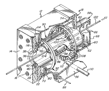
Figure 1 is a fragmentary perspective view of coating apparatus
embodying the present invention, showing a section of a
continuous length of wire being conveyed axially therethrough;
....
: ,
: .' 'I"' " ",,
. . ,
' ;:''' ~ '~'
:.
:
.
~695~
Figure 2 is a fragmentary view showing components of the
apparatus of Figure 1 used for conducting electrical power to
th~ electrode components thereof, taken along line 2-2 of
Figure 3 and drawn to a greatly enlarged scale;
: Fi~ure 3 is a fragmentary view of the apparatus of Figure
1, drawn to an enlarged scale, in pa.rtial vertical section and
with portions broken away;
Figure 4 is a sectional view of the apparatus at the
inlet end, taken along line 4-4 of Fiqure 3 and drawn to a
reduced scale;
Figure 5 is a view of the apparatus from the outlet end,
drawn to the scale o~ Figure 4 and in partial section;
Figure 6 is a diagrammatic representation of a system
embodying the present invention;
Figure 7 is an elevational view of a second form of
apparatus embodyin~ the invention, with a portion of the
chamber-defining housing broken away to expose internal parts;
and
Figure 8 is a fragmentary perspective view, in partial
section, of the porous cylindrical member employed in the
coating unit of the inven-tion, diagrammatically suggesting the
tubular cloud of helically moving charged particles, and the
radial attraction thereof to a rectangular conductor being
convey~d therethrough.
Turning now in detail to Figures 1-5 of the appended
drawings, t.herein illustrated is an electrostatic coating unit
:: embodying the present invention, consisting of a housing
assembly within which i5 supported a porous cylindrical
member, generally designated by the numeral 10. The housing
consists of a central section, generally designated by the
: : . : .
5~
numeral 12, having at its inlet end an end plate 14, secured
by screws 16; an outlet section, generally designated by the
numeral 18, is similarly secured at the opposite end of
Section 12. A circular inlet opening 20 is formed through the
end wall 22 of the central housing section 12, and is
surrounded by an annular groove 24 within which one end of the
cylindrical porous member 10 is seated. A recess 26 is formed
into the inner surface of the end plate 14 and serves to seat
- an inset piece 28. The latter has an inwardly eurled,
circumferential lip element 30, which defines and surrounds a
central aperture 32 through the piece 28, and which merges
into a circumferential groove 34, of generally semic:ircular
cross-section, which is formed into the outer ace thereof.
The end plate :l4 has a similar, inwardly curled
circumferential lip element 36 thereon, which surrounds and
defines the central aperture 38 therethrough. The lip element
36 cooperates with element 30 and the circumferential groove
34 to define a pa~sageway of generally circular cross-section,
which opens through a narrow circular gap defined between the
lip elements 30, 36. An insert 40 is seated within khe
passageway formed between the end plate 14 and the inset piece
28, and i9 circumferentially tapered (as best seen in Figure
4) so as to define a complementarily tapered flow passage 42. ~:
The latter communicates with the chamber space 44 wi~hin the
central housing ection 12 through a duct 46, which extends
through the end wall 22.
The opposite end o the cylindrical member 10 is
supported by seating it within a similar annular groove 48,
which surrounds the opening 50 formed through the end wall 52
of the outlet section 18. A wall portion 54 extends axially
:, , .
' ' .
~i9' ;7~
inwardly from the end wall 52, and is telescopically received
within the wall port-ion 56 of the central housing section l~.
Consequentially, it cooperates therewith to define the
internal chamber space 44 of the housi:ng assembly, which
provides a plenum about the cylindrical porous memb~r lO.
Structure extending from the opposite side o the wall
: portion 52 of the housing section 18 p]rovides an exhaust
chamber, generally de~ignated by the numeral 58, which is
divided into two internal, substantially identical
compartments 60 by a partitioning wall 62. As is best seen in
Figure 5, the chamber structure is such a3 to define a
cross-sect:ional conf.iguration for the compartments ~0 which is
of progressively enlarged dimension~ toward the outlet port~
64, with respect to the openingq 66 through the partitioning
wall 62 and the end wall 68 of the chamber.
An annular rib 70 is formed within the central section 12
Q~ the housing a~sembly, and it has an annular track component
72 secured, by screws 74, against an inside surface portion
76. A similar track component 72 is attached to flange
element~ 78 formed about the inner periphery of the wall
portion 54 of the housing section 58. A circular bore 80
extends through the outer wall 56 of the central section 12
and within the annular rib structure 70; at its inner end is
~; disposed a receptacle component 82 which defines an elo.ngated
socket 84. The socket is adapted to Erictionally engage the
plug 86 on the end o~ the cable 88 (attached to a power
supply, not shown), ~o as to enable electrical connection to
the txack componen-t 72 through the screw 74.
An electrode assembly is disposed within the plenum o~
the coating unit, about the cylindrical porous member 10, and
_g _
9S7~
consists of a number of electrode components, generally
designated by the numeral 90 (although three are shown, more
or fewer may be found desirable under certain circumstance~,
which are supported by ring members, generally desiynated by
the numerals 92 and 94. Each electrode component 90 consists
of a bar 96, from the inner surface of which pro~ects a line
of needles or pins 98. A pair of tabs 100 project from the
outer surface of each bar and receive fastener elements 102,
by which they are attached to the ring members 92, 94. A
flanged wheel 104 is secured to the outer end of each of the
fastener elements 102, and is rotatable thereon and upon the
inner edge 106 oE the associated track component 72. In this
manner, the e1ectrode components 90 are assembled with the
ring members 92 and 94 to provide an electrode assembly which
is rotatable, on the track components 72, about the
cylindrical member 10.
Whereas the ring member 92 is of relatively simple
construction, member 94 is more complex in that it mounts an
array of vane elements 108. A conduit 110 (from an air
supply, not shown) extends through the wall 56 and terminates
in a nozzle 112; the latter i8 disposed adjacent the inner
side of the ring member 94, upon which the vane elements 108
are mounted, and extends generally tangentially thereto.
~hus, air flowing through the conduit 110 will impinge upon
the vane elemen~s 108, thereby providing the motive force for
driving the electrode assembly so as to rotate it in the
direction indicated by the arrow in Figure 1.
In operation, high voltage electrical power is supplied
to the electrode components 90 through the cable 88, all of
the intervening and contacting parts being fabricated of an
--10--
~2~9~
electrically conductive material. Pressurized air introduced
through the conduit 110 not only causes the cage-like
electrode assembly to rotate, as described, but the air also
becomes ioni7.ed by contact with the electrode components. As
is well known in the art, the efficiency o~ ionization is
;. maximi~ed by contact of the air with the poin-ted end of the
needles 98: the desirability of utiliæing elements of
increasing radial lengths in the downstream direction of -the
coating path, as illustrated, has also been recognized
previously (see the above-identiied Dunford et al patent).
Coating powder is introduced into the apparatus through
the tapered throat 114 that is ormed between the end wall 22
of the housing section 12 and the plate 14 and inset piece 28
secured thereto. A duct 116 i9 formed through the wall 22,
and establishes communication between the throat 114 and the
plenum provided by the chamber space 44 within the housing;
consequently, the same air that is introduced through the
conduit llO flows into the throat 114 and assists in
delivering the powder, which is supplied thereto through the
: 20 inlet fixture 118, as indicated by the arrow in Figure 3.
As will be appreciated, air from the plenum also passes
through the duct 46 into the flow passage 42 formed by the
wall 14, the piece 28 and the insert 40, and it will circulate
therethrough and pass outwardly through th~ circular gap
formea between the lip elemenes 30 and 36; the decreasing
cross-section of the passageway serves of course to maintain a
substantlally con~tant exit velocity, and thereby to promote
uniform flow.
Because of the coniguration o~ the parts, the air
issuing will proceed along a helical, vortex-like path. It
,
~ .
~ X~957~
will pick up the particulate coating material 136 passing from
the adjacent outlet end of the throat 114, and will thereby
produce a cloud of particles of generally -tubular
configuxation, moving along a helical path; the general form
of the cloud is indicated in Figure 8, although it will be
appreciated than less di~tinct boundaries, thickness
variation, and the like may exist in practice.
The cloud exits from the cylindrical member 10 through
the opening 50 in the end wall 52, and suitable fans or
blowers (not illustrated), attached to coupling fixtures 120
at the outlet ports 64 of the exhaust chamber 58, assist such
movement. As will be appreciated, the convolute con~iguration
o~ the compartments 60 within the chamber 58 will cooperate
with the vortex structure at the inlet end to promote the
desired helical ~low of the gaseous suspension of paxticles,
the induced swirling action being in the same direction at
bo~h locations.
In addition to serving its other functions, the air
introduced through the nozzle 112 also flows through the pores
of the cylindrical member 10. In doing so, it forms what may
be rePerred to as a generally cylindrical "volume'l of moving
gas ~notwithstanding that the gas streams in the pores, of
which the gas volume is comprised, are not integrated), in
which mass transfer i8 substantially limited to radial inward
flow. Not only does this gaseous flow ensure that no deposit
o~ coating material particles will form on the interior
surfaces of the cylindrical member, but it is also believed to
contribute to the fluidized state of the powder. Because of
the former effect, no clu~ps of powder can form above the
workpiece travel path, which would otherwise tend to
-12-
.
" .''''~, :
3L2~95~
accumulate and fall upon the wire 122, thereby producing flaws
in its coating.
The powder is charged by the ionized air, produced by
contact with the needles 98 of the electrode components, as
described. Electrostatic charge may in turn be transferred
from the air to the powder particles within the throat 114, or
upon contact of the powder with the air issuing ~rom the
vortex structure at the inlet of the unit, and/or within the
cylindrical member lOo In any event, the particles are
attracted to and deposited upon the wire workpiece 122 as it
moves therethrough (in the direction indicated by the arrow),
the wire of course normally being grounded for that purpose.
Turning now ~o Figure 6 oE the drawings, a typical
electrostatic coating system embodying the pxesent invention
is diagrammatically illustrated and consists, in addition to a
coating unit as previously described, of wire pay-off and
take-up mechanisms 124, 126, respectively, for conveying the
wire 122 horizontally therethrough, heating and cooling units
128, 130, and a motor 132 or driving the take-up mechanism
126; as will be noted, the latter is grounded. It will be
appreciated that a system embodying the invention will
normally include other features and subsystems as well,
including a powder supply and circulation subsystem, wire
cleaning devices, control mechanisms and electronics, and the
like~
A second embodiment of the coat~ng unît of the invention
is illustrated in Figure 7, and is virtually the same as that
hereinabove described with the exception that the electrode
components, generally designated by the numeral 134, are
stationary rather than being mounted for rotation. Thu8, the
-13-
~.
~ ~i95~
bars 96'are simply affixed to the rib 70 and flange elements
78, to remain in preselected locations about the cylindrical
member 10. ALthough it is believed that a xotating electrode
assembly may afford better efficiency of charging, and will
avoid excess metal within the unit (which can create undue
capacitance and thereby affect -the uniformity of the coating),
the use of fixed electrode components represents a practical
alternative which may be preferred in certain circumstances.
Finally, with reference again to Figure 8, it will be
noted that the worXpiece 122' is a conductor of rectangular
cross-section. Coating uniformity is particularly difficult
to achieve upon such a substrate utilizing prior electrostatic
fluidized bed coating techniques; this is attributable
primarily to density variations ln the powder cloud, and to
the presence of the sharp edges on the wire. The inqtant
invention obviates those difficulties due, in large measure,
to the radial movement of the particles from the cloud to the
workpiece, as indicated in the Figure. This and other
advantages of the tubular cloud form are discussed more ~ully
in the Dunford et al patent, previously referred to.
In addition, however, the present invention avoids the
need or any supply of powder to be maintained within the
apparatus, as has heretofore been necessary with electrostatic
fluidized bed coating equipment. This not only minimizes the
amount of powder that must be maintained within the ~ystem,
and thereby permits the use of a lower capacity powder
recovery system and dust collector, but it also avoids the
need for any leveling device to maintain a bed o particles at
a proper depth for satisfactory operation. Moreover, units in
which a reservoir of powder iB maintained must be emptied out
-14-
.
.
2 ~
~ ~;9~
during periods of nonuse (such as overnight), so as to avoid
moisture-associated problems.
A particular benefit of the pxesant apparatus resides in
the fact that there is no opportunity for powder to build up
on surfaces adjacent the travel path for the workpiece, as
discussed above, and further advantages concern efficiency and
safety of operation. Because of the physical relationship of
the parts, the electrode components may be disposed in close
proximity to the workpiece without arcing; consequently, high
levels of efficiency are possible at reduced voltages.
Furthermore, there is minimal r.isk to personnel, since the
electrodes are not exposed. The units of the invention may be
operated at electrode potentials of 20 to 30 kilovolt~, as
contrasted with prior art apparatus which has, in the best
case, typically required at least 40 to 50 kilovolts for
optimaL operation, and generally much higher voltage levels
were necessary.
Finally, a substantial advantage of the units of the
invention resides in their relativaly small size and cost of
manufaature. Outside dimensions of existing equipment may
typically be five to six feel long, four feet high, and one
foot wide; on the other hand, the present apparatus ~ay
suitably be only three feet long and one and one-half feet
square.
Except for the metal electrical components, the coating
apparatus may be made virtually entirely of nonconducting
synthetic polymers, and this includes the porous cylindrical
member (which may be fabricated from the same ~aterials as
have heretofore been used for the porous plates of fluidized
bed units). It will be unders-tood that many variations are
-15-
''',,.
~6957~
possihle in the configuration and construction of the housing,
the electrode assembly, and the other parts and components of
the apparatus and the system, without d0parting from the
concepts of the present invention. For example, the powder
feed system employed may be specifically clesigned to-provide a
highly consistent flow rate, or optimal results.
In it~ broadest sense, the invention contemplates
apparatus in which a tubular cloud of charged particles Elows
helically through a generally cylindrical member, whether
porous or not; it is believed that such apparatus has not
existed heretofore, and that the vortex creating structure
described herein will produce the necessary tubular cloud.
However, the use of a porous member, and the other Eeatures
described herein, achieve optimal results and are of course
preferred.
Thus, it can be seen that the invention provides a novel
and improved method, apparatus, and system by which
workpieces, and particularly conductors of continuous length,
can be coated by electrostatic powder deposition, quickly,
efficiently, safely, and with an exceptionally high degree of
uniformi-ty in the build. The coating unit is smaller than
prior art apparatus of comparable effectiveness and
efficiency, and utilizes less coating powder, with the
attendant advantages discussed above. Coating can be carried
out at voltage levels that are significantly reduced from
those heretofore employed for practical high-speed operation,
thereby further enhancing saety. The nature of the coating
can readily be controlled by the speed of the workpiece and
the magnitude of the voltage applied; the deposit is highly
tolerant of changes of workpiece position within the cloud of
-16-
~'~6957~
charged particles, and is virtually unaffected by normal
fugitive electrical effects, such as noise and static.
Production economy is maximized by the avoidance of
significant waste during start-up and discontinuances of
operation, and th~ coating unit is uncomplicated and
~,
; relatively inexpensive to manufacture and operate.
`~:
':
"
:,:
: -
''~
`
~: :: : :
,~
::: : :
;:: : :
.;:
-17-
,