Note: Descriptions are shown in the official language in which they were submitted.
SMOKE AND FIRE PROTECTION SYSTEM FOR ELEVATORS
BACKGROUND OF T~E INVENTION
FIELD OF THE lNVENTION
1 This invention relates to new and useful improve-
ments in systems for permi~ting the use of elevators during
a building fire.
DESCRIP~ION OF THE PRIOR ART
In most elevators lobbies in the United States,
there are signs warning against the use of elevators in the
event of fire and directing the building occupants to use
marked exits stairways. The National Fire Protection
Association (NFPA), Life Safety Code lists the following
problems involved with the use of elevators as fire exits:
If an elevator call button has been pushed at that
level, an automatic elevator may stop automatically at the
floor involved in the fire and open automatically, thus ex-
posing occupants to fire and smoke~
A large number o~ people attempting to crowd into an
elevator in case of fire might prevent the doors from
closing and make it impossible for the elevator to start.
If electric supply cables are damaged during a fire,
the elevators may be rendered inoperative and trap occupants
in elevators stopped between floors. There might not be
time to permit rescue of trapped occupants through emergency
escape hatches or doors.
1 Persons seeking to escape from a fire by means of a
elevator may have to wait at the elevator door for some
time, during which they may be exposed to fire, smoke or
developing panic.
In most multistory buildings, the elevators are set
to descend automatically to the ground floor in the event of
fire~ Fire fighters have keys to control elevators manually
during building evacuation and fire fighting.
Since smoke infiltration into elevator shafts fre-
quently threatens lives and hinders elevator use by fire
fighters, it is current practice in some buildings to
provide top vents in elevator shafts serving more than three
floors to allow the elevator shaft to act as a smoke shaft
carrying smoke from the fire floor out of the building.
Because of leakage around elevator doors, however, this
feature may contribute significantly to smoke movement
beyond the fire floor by way of elevator shaft itself.
Several suggestions have been made to permit the
utili~ation of elevators in buildings during fires. The use
of elevators may be needed for the evacuation of physically
handicapped persons who can not walk down the stairways.
The elevators may also be needed for the use of fire pro-
tection or fire control personal.
2~
1 One of the proposals for assisting in the evacuation
of buildings is seen in Heba U.S. Patent 3,952,452 which
discloses the use of a blower to pressurize stairwells to
keep out fire and smoke and to assist in the opening of
doors which might otherwise be held shut by a pressurize
differential. In Koplon U.S. Patent 3,817,161 a system is
shown wherein the elevator shaft or hoistway is pressurized
by a blower to keep the shaft free of smoke and reduce the
hazard of suffocation. The elevator is also designed for
drawing air from the hoistway to discharge into any given
floor through the open elevator doors to clear smoke from
that level.
ASHRAE journal~ April 1984, pp.23 - 33, discusses at
length the problem of smoke control for elevators which need
to be used during a fire either for evacuation of building
occupants or for use by fire department personnel.
Heating-Piping-Air Conditioning, April 1984 includes several
articles dealing with smoke control in multistory buildings.
The foregoing references do not suggest the concept
of this invention, viz., the continuous pressurizing of an
elevator cab to permit its use during a fire for building
evacuation or for use by fire department personal.
38~3~
SUMM~RY OF THE INVENTION
Accordingly this invention seeks -to provide a new and
improved system, apparatus and method for protecting elevators
from fire and smoke to permit their use during fires.
Further the invention seeks to provide an elevator
system having means for ventilating an elevator cab during its
entire range of vertical movement.
Still further the invention seeks to provide an elevator
system having a ventilator duct flexibly connected to an elevator
cab to supply fresh air in high volume and at a positive pressure
to prevent inflow of smoke when the doors are closed and to flow
outward to clear the smoke away when the doors are opened.
The invention also seeks to provide an elevator system
having a ventilator duct extending vertically for the entire length
of the hoistway with a continuous connection to the elevator cab
to supply fresh air in high volume and at a positive pressure to
prevent inflow of smoke when -the doors are closed and to f:Low
outward to clear the smoke away when the doors are opened.
The invention in one broad aspect pertains to a smoke ancl
fire protection sys-tem for elevators comprising, ln combination a
multistory building having an elevator hoistway therein, the elevator
hols-tway beiny enclosed at the -top to prevent discharge of smoke
therethrough, an elevator cab positioned in the hoistway for move-
ment vertically therein and means for moving the elevator cab.
Duct means separate from and positioned in the hoistway has an in-take
outside the building for introduction of fresh air, is connected
to the elevator cab throughout the entire range of vertical
movement thereof, and includes a plurality of openings along -the
duct means into the hoistway, to supply fresh air separately to the
-5-~
~.~6~
hoistway and to the elevator cab. Ventilating means is connected
to the duct means to supply fresh air thereto to pressurize and
supply fresh air separately to the hoistway and the elevator cab.
Another aspect of the invention comprehends a method
of protecting an elevator cab in a building, positloned in an
elongated elevator hoistway for vertical movement therein, against
fire, smoke, or poisonous fumes or gases. The method includes
introducing fresh air from an intake outside the building through
a duct at high volume and positive pressure into the elevator
cab and separately from the duct through a plurality of openings
along the duct into the hoistway to ventilate the same and maintain
a positive pressure therein sufficient to effect a continous out-
flow of air when the doors are opened to blow fire, smoke or
poison fumes or gases away and to prevent the intrusion of smoke
or poison fumes or gases when the doors are closed.
Other aspects of the invention will become apparent
from time to time throughout the specification and claims as
hereinafter related.
- 5~ -
Briefly the invention comprehends a novel smoke and
fire protection system for elevators in a multistory buildiny
having an elevator hoistway therein, with an elevator cab having
vertical movement thereinO The hoistway is preferably enclosed
at the top to prevent discharge of smoke therethrough. A duct is
positioned in the hoistway connected to the elevator cab throughout
its entire range of vertical movement and has an elongated opening
extending for the full height thereof and sealed by a pair of
elongated strips of flexible material along each edge of the opening
meeting in sealing relation. A duct of elongated cross section and
bell shaped is secured on the cab and fits through the sealing strips
at the point of contact therebetween for movement with the cab along
the length of the elongated opening with ~he sealing strips main-
taining sealing relation ahead of and behind the elongated bell
shaped portion. A blower connected to the duct supplies fresh air
to the elevator cab and may include heatingl cooling, and filtering
apparatus for conditioning the air supplied therethrough. The
blower supplies fresh air at a volume and pressure sufficient -to
ventilate -the c~b and effec-t a substantial outflow of air on
opening the elevator and hoistway doors.
_ ~ _
BRIEF DESCRIPTION OF THE DRAWINGS
1 Fig. 1 is a plan view, partially in section, of a
building lobby and a bank of elevators illustrating a pre-
ferred embodiment of this invention.
Fig. 2 is an isometric view of an elevator cab
showing its connection to a ventilation system in accordance
with this invention.
FigO 3 is a partially schematic, vertical section
through a multistory building showing the elevator cab and
hoistway and regulating system comprising a preferred embod-
iment of this invention.
Fig. 4 is a horizontal section through the vertical
ventilating duct in the elevator hoistway showing the longi-
tudinal seals in a closed position, as shown with Fig. 2.
Fig. 5 is a horizontal section through the vertical
ventilating duct in the elevator hoistway showing the trans-
fer duct from the elevator cab extending through the seals~
as shown with Fig. 2.
Fig. 6 is a view in longitudinal section of the
transfer duct shown in Figs. 5 and 8.
Fig. 7 is a view in longitudinal central section of
the transfer duct shown in Fig. 6.
Fig~ 8 is a view in horizontal section at the eleva-
tor lobby level showing the elevator cab and its connection
to the ventilating system.
1Fig~ 9 is a vertical section through the elevator
cab illustrating the connection between the cab and a pres-
surized air supply duct for continuous ventilation during
operation of the elevator.
5Fig. 10 is a roof plan view of the elevator cab of
Fig. 9 showing the air supply connection in horizontal sec-
tion.
Fig. 11 is a view similar to Fig. 9 of the elevator
cab illustrating an alternate embodiment in which a high
10pressure, high volume blower is provided for supplying air
into the cab.
Fig. 12 is a view of the elevator cab similar to
Fig. 10 illustrating the relationship of the booster blower
to the transfer duct.
15DBSCRIPTION OF THE PREFERRED EMBODIMENTS
Referring to the drawings by numerous of reference,
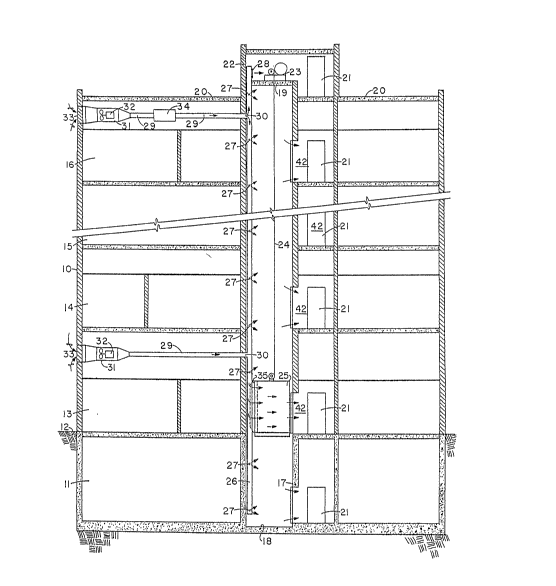
and more particularly to Fig. 3, there is shown a multistory
building 10 having a basement level 11 below the surface 12
of the earth and having a plurality of levels 13, 14, 15,
20and 16. The building may have any number of floors but the
application of the invention is normally used with buildings
having three or more floorsO
Building 10 has a hoistway or elevator shaft 17
which extends from a closed bottom 18 at the level of the
25basement 11 to a closed top 19 adjacent to the roof 20 of
the building. The building has doorways 21 at each level
.. . . ... . . . .
1 which open into a stairwell (not shown). The stairwell
opens at the top into a roof enclosure 22 in which there is
positioned the hoist mechanism 23 which operates the eleva-
tor. Hoist mechanism is shown as operating a cable 24 which
is connected to a elevator cab 25.
- ~ vertically extending air supply duct 26 extends
for the entire height of hoistway or elevator shaft 17. Air
~- supply duct 26 has a plurality of outlet openings 27 which
- d scharge air from the air supply duct 26 into hoistway 17
. . .
~ and an outlet opening 28 which discharges air into the roof
enclosure 22 for the elevator motor~ Air may also enter
. ~ .. . .
- the hoistway 17 by leakage around the connection to the
- ~ elevator cab as described below.
The building is supplied with one or more air sup
;~ 15~ plies leading to the vertical supply air duct 26. In Fig.
- ~ 3, there are shown two such air supplies, although any suit-
able number could be used according to the needs of a build-
,
ing of a given height. The lower air supply duct 29 opens
~ illtO vertical air supply duct 26 a~ indicated at 40. Air
supply duct 29 is connected through an enlarged housing 31
which contains a high capacity blower 32 and which opens
through an air inlet 33 to the exterior of the building.
The upper air supply is the same as the lower air supply but
has the ~upply duct 29 shown in two parts with a heating
and/or cooling section 44 installe~ therein.
.... . _ .... _.. ~ . . .
1 The elevator cab 25 is provided with a transfer duct
35, shown schematically in Fig. 3, which cooperates with
vertical air supply duct 26 to conduct fresh air under
pressure into the interior of the cab to ventilate the cab
and maintain the air under a somewhat elevated pressure to
prevent smoke and flames from entering the cab either from
the hoistway 17 or from the elevator lobby on any level
where the elevator door opened.
In Figs. 4, 5, and 8 - 12, the supply air transfer
duct 35 i5 shown in more detail. In fact, the transfer duct
35 is shown in a somewhat exaggerated scale in relation to
the cab 25 and the vertical air supply duct 26. In Figs. 9 -
10, transfer duct 35 is L-shaped in vertical cross section
and has an elbow portion 36 which opens into the top of
elevator cab 25 and has bell shaped air inlet portion 37
which extends into vertical air supply duct 26. The elbow
portion 36 of transfer duct 35 extends to a circulating fan
38 (Figs. 11 - 12) which assists in blowing air into the
elevator cab 25 through a conventional ceiling distribution
panel 39.
Vertical air supply duct 26 has a vertically extend-
ing seal consisting of two separate flexible sealing
elements 40 and 41, of rubber, elastomer, impregnated felt,
impregnated fiberglas, etc., which extend along the entire
length of the air supply duct 26. The sealing elements 40
and 41 are sized to meet each other in sealing relation
--10--
3~
1 along the entire vertical length of duct 26 except for the
portion into which the bell shaped air inlet portion 37 of
transfer duct 35 extends, see Figs. 4, 5 and 8.
The bell shaped inlet portion 37 of transfer duct 35
is operable to be moved vertically along the entire length
of air supply duct 26 with the movement of elevator cab 25
and provides a vertically moveable inlet for supply of air
into the elevator cab 25 at any point in its movement from
the basement to the top floor.
Fig. 8 illustrates an embodiment having ~wo air
supply ducts 26 and two transfer ducts 35 for elevator cab
25. The structure is otherwise substantially the same as
previously described. In Fig. 8, there is also shown some
of the detail of the relationship of the elevator cab 25 to
the lobby and to the hoistway and elevator doors. In Fig.
8, the elevator lobby 42 has a doorway 43 opening in-to
hoistway 17. Hoistway doors 4g and 45 are opened and closed
by conventional operating means. Elevator cab 25 is like-
wise shown with doors 35 and 46 in an open position.
In this view, the flow of air is shown by the dir-
ectional arrows as providing fresh air under pressure to the
interior of elevator cab 25 which air tends to blow outward
into elevator lobby on opening of the elevator doors 46 and
47 and hoistway doors 44 and 45 to prevent the intrusion of
smoke and flames into the interior of elevator cab 25.
38~)
1 In this embodiment, transfer duct 35 is of a elong-
ated shape as shown in Figs. 6 and 7. This embodiment of
transfer duct 35 has a rectangular base plate 48 connecting
it to a like opening on the rear wall of elevator cab 25 and
has a bell shaped opening 37 as in the other embodiments
shown in Figs~ 9 - 12. In this embodiment, the air supply
is through a pair of transfer ducts 35 which slide up and
down a pair of air supply ducts 26.
In Figs. 9 and 10, there is shown an alternate em-
bodiment of the invention in which transfer duct 35 is
connected through a high capacity blower 50 which opens
through a diffuser 51 to supply air through air diffuser
plate 39 as in the other embodiments of the invention. The
blower 50 is of a sufficient capacity to repressurize the
fresh air brought in through supply duct 26 to an amount
sufficient to maintain the interior of cab 25 under a
substantially elevated pressure to prevent intrusion of
smoke and fire when the elevator doors 46 and 47 are opened.
In this embodiment, transfer duct 35 has a bell shaped outer
end portion 37 and is elongated in shape as described for
the other embodiments. The supply air duct 26 is provided
with a vertically extending seals 40 and 41 in which the
bell shaped air inlet opening 37 extends.
-12-
~2~i9~
OPERATION
1 The operation of this invention should be fairly
evident from the description of the construction and assem-
bly of the various parts. Nevertheless, a more thorough
description of operation will be given to facilitate a
complete understanding of the invention~
This invention i a system or apparatus which per-
mits the continued operation of elevators during a fire to
permit evacuation of occupants from the building and to
facilitate the rapid movement of fire department personnel
and equipment. The invention consists of a system and
apparatus which provides for a continuous ventilation of the
hoistway 17 while maintaining the elevator cab 25 thoroughly
ventilated with fresh air at a sufficiently elevated press-
ure to prevent the intrusion of smoke or fire into the cab
from the hoistway 17 or from any of the elevator lobbies or
floors where fire or smoke might be present~
In normal operation, the supply air blowers 3~
provide a positive flow o~ fresh air, drawn from the exter-
ior of the building through air supply inlets 33, through
the hoistway 17 and elevator cab 25 of approximately 35 - 50
ft./min~ to prevent the entry of smoke generated by an early
fire condition prior to activation of the emergency smoke
removal system. The air supply system may include a cooling
or heating section 34 as shown at the top o~ Fig. 3. This
is an optional eature which can be eliminated or can be
38~
1 included at one or more of the air supply levels.
In emergencies, i.e. fire, the air supply fan for
the elevator cab 25 and hoistway 17 is automatically opera-
ted by the smoke detection and/or fire detection system (not
shown) at the high speed operation required to maintain a
positive airflow through the cab such that when the doors
are opened the outflow will be not less th~n 200 ft./min.
velocity and at a pressure differential of at least 0.1 in.
water of the hoistway in relation to the lobby.
The air is drawn from the exterior of the building
and introduced by blowers 32 into vertically extending air
supply duct 26 which is sealed along its entire length by
flexible seals 40 and ~1 as described above. The air which
exits from supply duct 26 through openings 27 or through
leakage around the seals 30 and 41 supplies the hoistway 17
with air to ventilate it for its entire length during normal
operation and which serves to keep the hoistway 17 clear of
smoke and flames during a fire.
Elevator 25 is moved upwardly and downwardly in
hoistway 17 by elevator motor or hoist mechanism 23 which is
of conventional construction and operated in a conventional
manner. As elevator cab 25 moves up and down shaft or
hoistway 17, the transfer ducts 35 move up and down the
vertical shaft 26 with the flexible seals 40 and ~1 sealing
the opening from the supply duct 26 immediately behind and
immediately ahead of the transfer duct~
1 The vertical air supply duct 26 is therefore sealed
along its entire length except for the opening into which
the transfer duct 35 extends. There may be a slight leakage
of air from supply duct 26 through the seals 40 and ~1
adjacent to transfer duct 35, but otherwise the duct is
sealed through its entire length. Seals 40 and 41 therefore
provide a sealed but movable opening along the entire length
which provides introduction of air through trans~er duct 35
into the interior of elevator cab 25 as previously
described.
This arrangement therefore will maintain cab 25
thoroughly ventilated and at a somewhat elevated pressure
relative to the interior of the building, especially the
lobby areas where the doors may be opened. The elevated
pressure in cab 25 prevents smoke or fire from entering the
cab from elevator shaft or hoistway 17. Likewise, when the
elevator doors and the hoistway doors are opened at any
given level, the air pressure inside ele~ator cab 25 causes
the air to flow out into the lobby or landing ~2 and thus
tends to blow the smoke and flames away from the open door
of the cab if it has stopped on a level where there is a
fire.
While this invention has been described as a s~stem
of apparatus permitting the use of elevators during a fire,
it is also a general purpose system of supplying air to an
elevator cab to permit its operation in an unsafe air envir-
1 onment. For example, the system and apparatus could be
installed in a mine shaft to provide fresh air to an
elevator cab which has to move through unsafe air
conditions, such as layers or zones of noxious gases or
fumes.
While this invention has been described fully and
completely with special interest upon certain preferred em-
bodiments, it should be understood that, within the scope of
the appended claims, the invention may be practiced
otherwise than as specifically described herein.
-16-